Week 15. Interface and application
This week we were introduced to a new software called processing and taught how to code in processing, to draw canvas in three steps as a basics by our Guru Rico. Initially I do not have any codding idea, but now I can atleast scratch something and see it working.
Assignment
-
Individual assignment:
write an application that interfaces a user with an input &/or output device that you made
-
group assignment:
compare as many tool options as possible
This week group assignment lead was myself so I documented all the findings here. As a part of group assignment I tried making a simple GUI(Graphic User Interface) using processing. For this There were two parts to programming; coding the Arduino to receive a message via serial connection and turn the light on or off based on buttons I pressed on a computer interface.
Processing tutorial class
According to it’s page Processing is a flexible software sketchbook and a language for learning how to code for the visual arts. Download processing form here
Making canvas
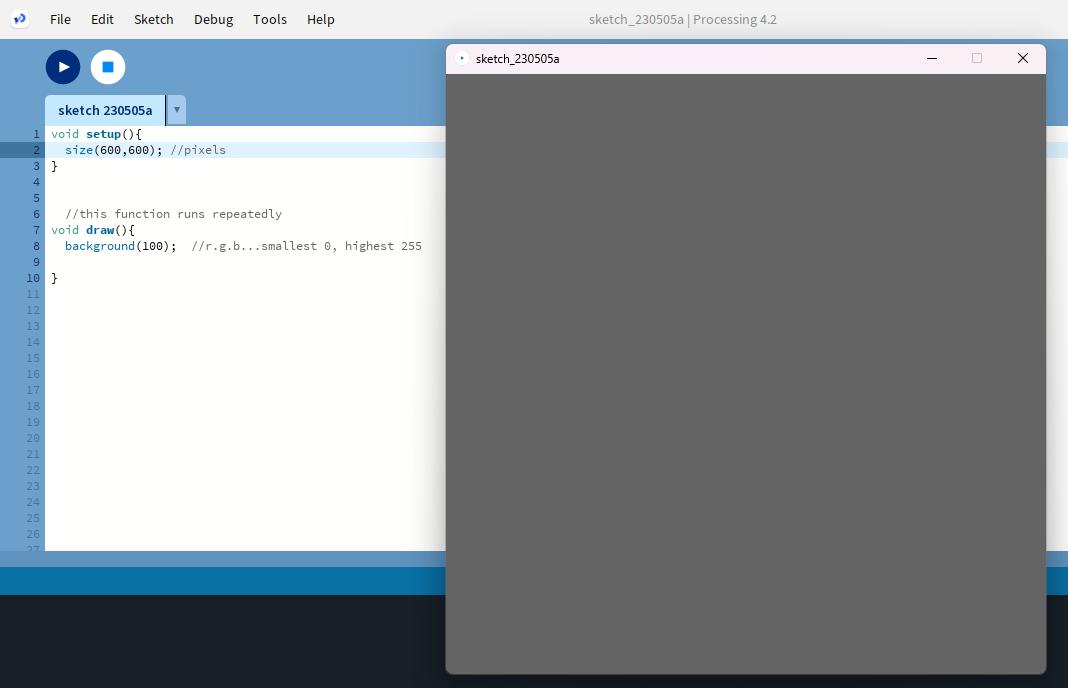
Step 1 - Making simple grey canvas of 600px by 600px.
  void setup(){
  size(600,600); //pixels
  }

  //this function runs repeatedly
  void draw(){
  background(100);  //r.g.b...smallest 0, highest 255
  }
- After codding click on play button to view the canvas.
- To get a different colours we can play with the numbers(r,g,b)
- Black (0,0,0)
- yellow(255,255,0)
- Red(255, 0, 0)
- Green (0, 255, 0)
- Blue (0, 0, 255)
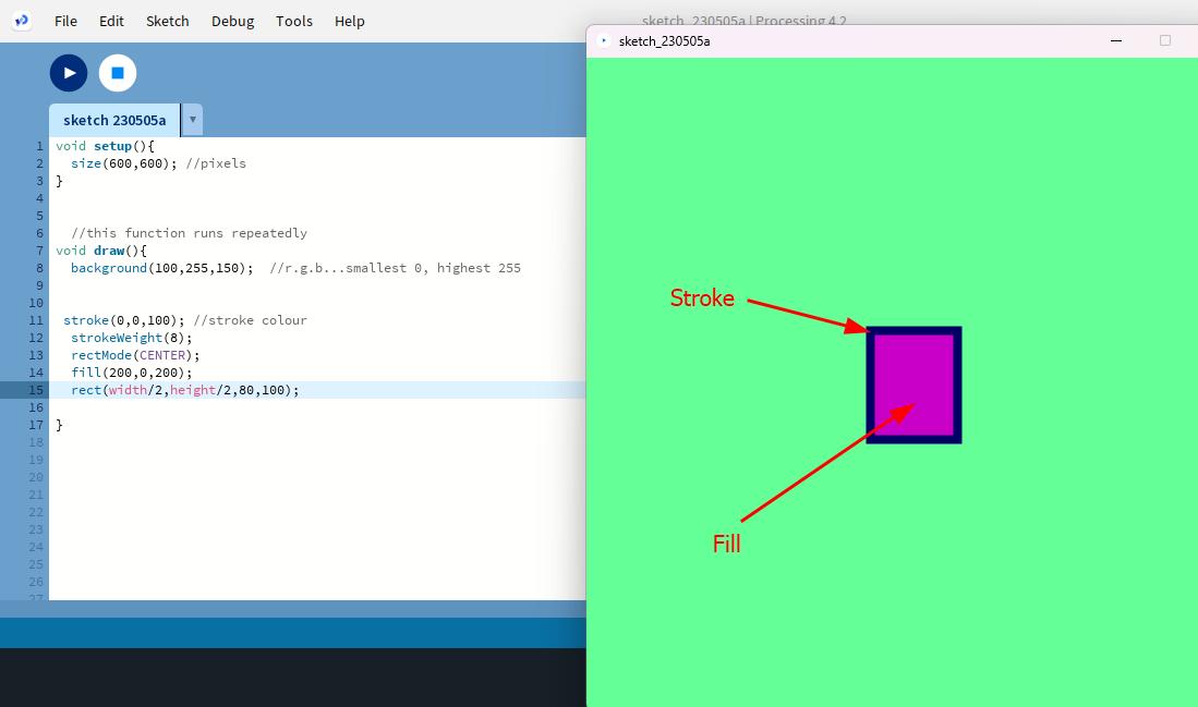
Step 2
- Drawing 2D shape and writing text inside canvas:
To draw rectangle >> rect
To draw circle >> circle
To give fill inside shape >> fill >> give colour number (rgb)
stroke weight >> stroke size
  void setup(){
    size(600,600); //pixels
  }

  //this function runs repeatedly
  void draw(){
    background(100,255,150);  // r.g.b...smallest 0, highest  255

  stroke(0,0,100); //stroke colour
  strokeWeight(8);
  rectMode(CENTER);
  fill(200,0,200);
  rect(width/2,height/2,80,100);

  }
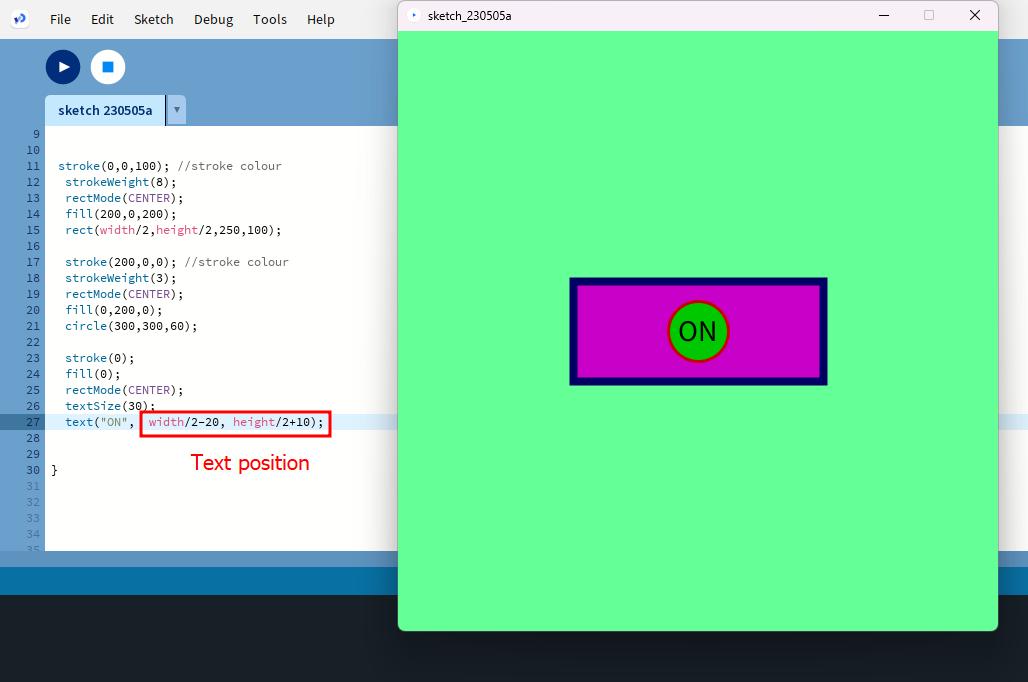
Step 3 - To make a Pointer: noCursor, mouseX, mouseY
  void setup(){
  size(600,600); //pixels
  }

  //this function runs repeatedly
  void draw(){
  background(100,255,150);  //r.g.b...smallest 0, highest 255

  stroke(0,0,100); //stroke colour
  strokeWeight(8);
  rectMode(CENTER);
  fill(200,0,200);
  rect(width/2,height/2,250,100);

  stroke(200,0,0); //stroke colour
  strokeWeight(3);
  rectMode(CENTER);
  fill(0,200,0);
  circle(300,300,60);

  stroke(0);
  fill(0);
  rectMode(CENTER);
  textSize(30);
  text("ON",  width/2-20, height/2+10);

  fill(255,0,0);
  noStroke();
  circle(mouseX, mouseY,30);

  }
Individual Assignment
For the individual assignment I am suppose to make a application that interfaces a user with an input or output device that we made. I will my final project board.
The detailed process on making GUI from scratch is in group assignment.
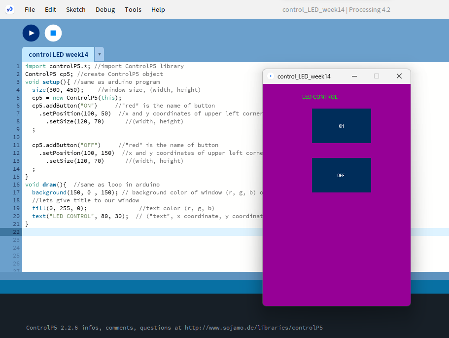
I want to control the LED to turn ON and OFF from the button I made.
Firstly I made a window and a [ON] and [OFF] button with the code below.
import controlP5.*; //import ControlP5 library
ControlP5 cp5; //create ControlP5 object
void setup(){ //same as arduino program
  size(300, 450);    //window size, (width, height)
  cp5 = new ControlP5(this);
  cp5.addButton("ON")     //"red" is the name of button
    .setPosition(100, 50)  //x and y coordinates of upper left corner of button
      .setSize(120, 70)      //(width, height)
  ;

  cp5.addButton("OFF")     //"red" is the name of button
    .setPosition(100, 150)  //x and y coordinates of upper left corner of button
      .setSize(120, 70)      //(width, height)
  ;
}
void draw(){  //same as loop in arduino
  background(150, 0 , 150); // background color of window (r, g, b) or (0 to 255)
  //lets give title to our window
  fill(0, 255, 0);               //text color (r, g, b)
  text("LED CONTROL", 80, 30);  // ("text", x coordinate, y coordinat)
}
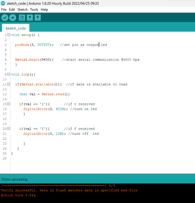
This is the Arduino IDE code I modified. Since my LED is in pin no.3 I replaced the pin number as my output.
void setup() {

  pinMode(3, OUTPUT);   //set pin as output

  Serial.begin(9600);    //start serial communication @9600 bps
  }

void loop(){

  if(Serial.available()){  //if data is available to read

    char val = Serial.read();

    if(val == 'r'){       //if r received
      digitalWrite(3, HIGH); //turn on led
      }

    if(val == 'f'){       //if f received
      digitalWrite(3, LOW); //turn off  led

      }
  }
}
Selected the board, chip and port(COM4) and uploaded the code above to my board.
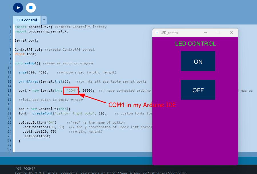
Setting up function in processing for buttons to turn LEDs ON and OFF based on char with the code.
import controlP5.*; //import ControlP5 library
import processing.serial.*;

Serial port;

ControlP5 cp5; //create ControlP5 object
PFont font;

void setup(){ //same as arduino program

  size(300, 450);    //window size, (width, height)

  printArray(Serial.list());   //prints all available serial ports

  port = new Serial(this, "COM4", 9600);  //i have connected arduino to com3, it would be different in linux and mac os

  //lets add buton to empty window

  cp5 = new ControlP5(this);
  font = createFont("calibri light bold", 20);    // custom fonts for buttons and title

  cp5.addButton("ON")     //"red" is the name of button
    .setPosition(100, 50)  //x and y coordinates of upper left corner of button
    .setSize(120, 70)      //(width, height)
    .setFont(font)
  ;


  cp5.addButton("OFF")     //"alloff" is the name of button
    .setPosition(100, 150)  //x and y coordinates of upper left corner of button
    .setSize(120, 70)      //(width, height)
    .setFont(font)
  ;
}

void draw(){  //same as loop in arduino

  background(150, 0 , 150); // background color of window (r, g, b) or (0 to 255)

  //lets give title to our window
  fill(0, 255, 0);               //text color (r, g, b)
  textFont(font);
  text("LED CONTROL", 80, 30);  // ("text", x coordinate, y coordinat)
}

//lets add some functions to our buttons
//so whe you press any button, it sends perticular char over serial port

void ON(){
  port.write('r');
}


void OFF(){
  port.write('f');
}
It is important to use the port that is in Arduino IDE run the sketch, otherwise it will give error when pressing play button.
When I press the button LED is not turning ON/OFF this was because I did not connect the serial UPDI for communication. When I connected it to UPDI it worked turning LED on and off.
Download zipped Code files here