Summary of my Final Project
Angays Calendar (Grandma’s Calendar)
For my final project I decided to make a calendar for my grandma and also specifically to the one who do not know how to read English since I got inspired by some perpetual calenders from pinterest.. The year is not written so it serves as perpetual calendar. I used the servo motors to drive the gears and rotate around to show the date,day and month in window.
Final Project presentation video
Final Project presentation slide
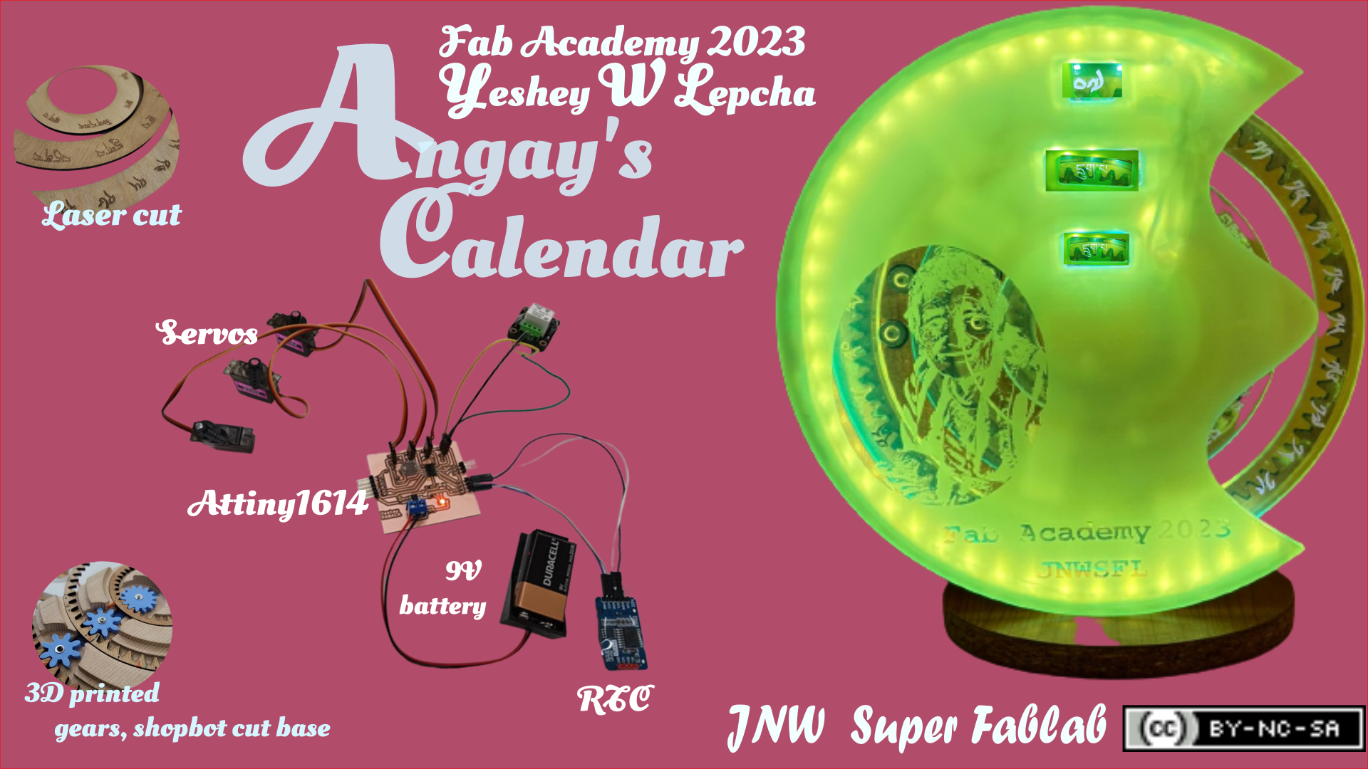
I used ATTiny1614 and a RTC module to keep track of time. i used RTC module as the input and servo motors as output. I also used LDR sensor to illuminate light at night using LED strip.
The estimated cost of the materials are listed below:
| Part | Provider | Quantity | Price | Total |
|---|---|---|---|---|
| Plywood Sheet 600x300x3mm | JNW Super Fab lab | 1 | $ 10 | $10 |
| PLA Filament (grams) | jnw Super Fab lab | 300 | $ 0.1 | $ 30 |
| Servo Motor 360 degree | JNW Super Fab lab | 3 | $ 2 | $ 6 |
| 9V battery holder | JNW Super Fab lab | 1 | $ 1 | $ 1 |
| PCB - Copper Board | JNW Super Fab lab | 1 | $ 0.2 | $ 0.2 |
| MCU - Attiny1614 SMD | JNW Super Fab lab | 1 | $ 1 | $ 1 |
| Resistor - 10k SMD | JNW Super Fab lab | 1 | $ 0.05 | $ 0.05 |
| Resistor - 220 Ohm SMD | JNW Super Fab lab | 1 | $ 0.05 | $ 0.05 |
| Capacitor - 0.1uF SMD | JNW Super Fab lab | 2 | $ 0.3 | $ 0.6 |
| LED - 2V SMD | JNW Super Fab lab | 4 | $ 0.2 | $ 0.8 |
| Male header angle 2.54mm -1X6 | JNW Super Fab Lab | 2 | $ 1 | $ 2 |
| Male header angle 2.54mm -1X3 | JNW Super Fab Lab | 2 | $ 0.5 | $ 1 |
| Female header 2.54mm - 1X3 | JNW Super Fab Lab | 4 | $ 1 | $ 4 |
| Female header 2.54mm - 1X4 | JNW Super Fab Lab | 2 | $ 1 | $ 2 |
| Female header 2.54mm - 1X2 | JNW Super Fab Lab | 2 | $ 0.5 | $ 1 |
| Voltage regulator AMS1117 5.0 | JNW Super Fab Lab | 2 | $ 1 | $ 2 |
| Male to male jumper wires | JNW Super Fab Lab | 12 | $ 0.01 | $ 0.12 |
| Female to male jumper wires | JNW Super Fab Lab | 12 | $ 0.01 | $ 0.12 |
| Terminal block | JNW Super Fab Lab | 2 | $ 0.5 | $ 1 |
| 9V dracell battery | JNW Super Fab Lab | 3 | $ 1 | $ 3 |
| LDR sensor | JNW Super Fab Lab | 1 | $ 0.5 | $ 0.5 |
| LED strip | JNW Super Fab Lab | 1 | $ 2 | $ 2 |
| Total | $ 68.44 |
Designing physical parts
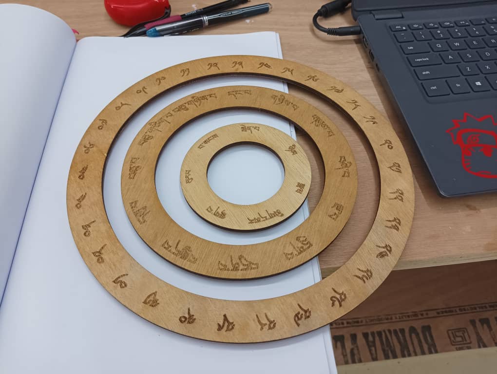
Firstly I designed a ring assembled with a stand and a base. The engraved text was made in Inkscape because the one I made in Fusion360 gets distorted once imported in Inkscape.
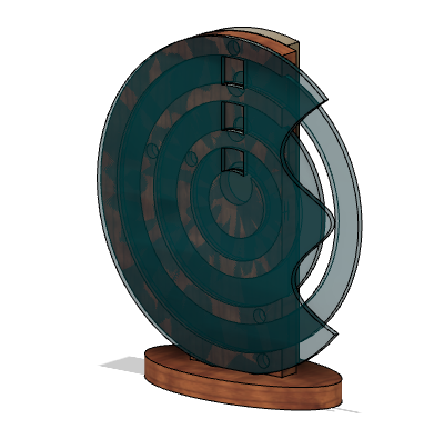
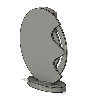
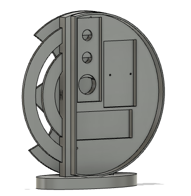
This is the view of assembled physical builds.
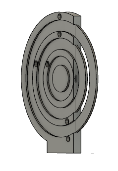
Designing a ring, stand and a base.
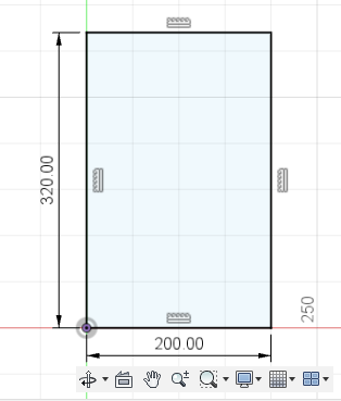
Firstly I designed a back stand with a height 320mm and width 250mm. I extruded it to 20mm as I am using 20mm hardwood.
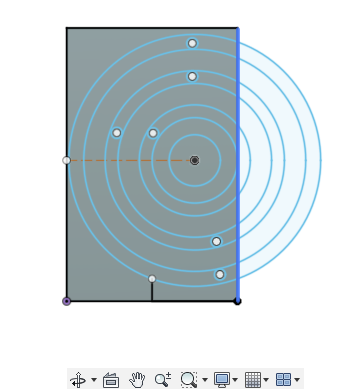
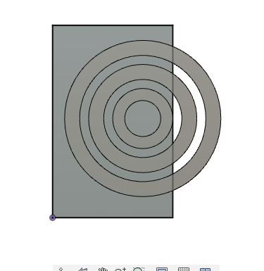
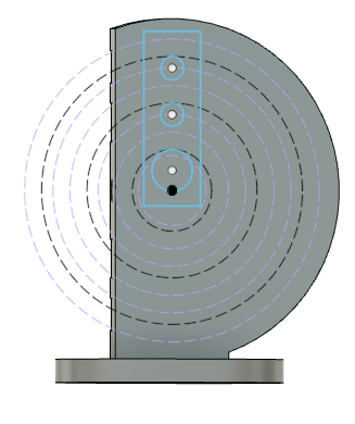
I selected the front surface of the stand to draw a circle on it for rings. I drew a circle to make ring of a width 25mm and extruded to 5mm thick as I am going to use plywood to make a ring. I made three rings of equal size keeping the gap 30mm in between.
I resized the back stand in simi-circular shape and did a extrude cut. I made a circle of 13mm(Outer diameter of bearing) and extruded to -10mm to make a bearing slot.
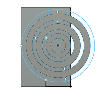
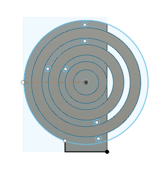
I moved the rings to Z- direction upto 10mm and did a combine cut to create a slot.
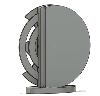
I made a front cover in a half moon shape and used spline line to make a curve surface.
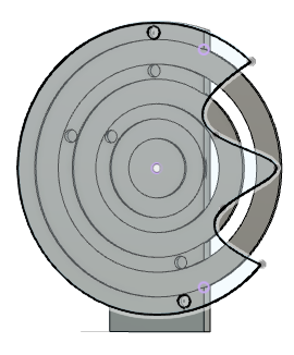
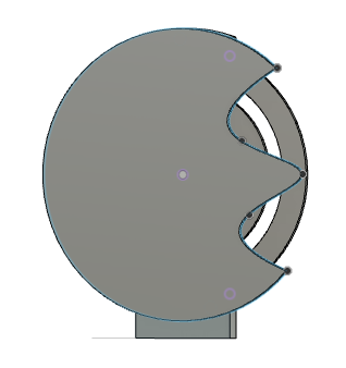
I created the sketch at the bottom of the stand using ellipse tool and extruded to 20mm.
I used a combine tool to make a slot at the base to cut in shopbot.
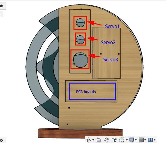
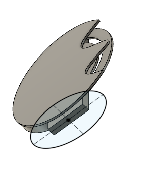
I mounted the electronic components from the back, for this I made a slot for servo motors and a slot to hold the servo motor. I used 3D printed base to clamp servo motors.
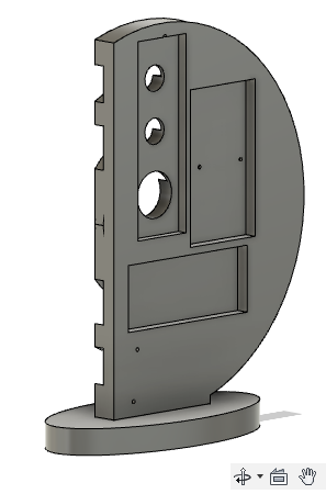
To cover the electronics component I used 3D printed cover. To design a cover I offset a plant at a distance of 0 and created a sketch. I extruded it to 30mm height.
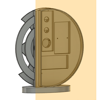
TO make a complete cover I selected the top round surface and created a semi circle sketch. Extruded it to 3mm to make a complete cover.
Designing gears
To drive the rings I used servo motors and gears. Designing the gears was bit challenging so I referred some tutorials.
To design a gear I referred this tutorial.
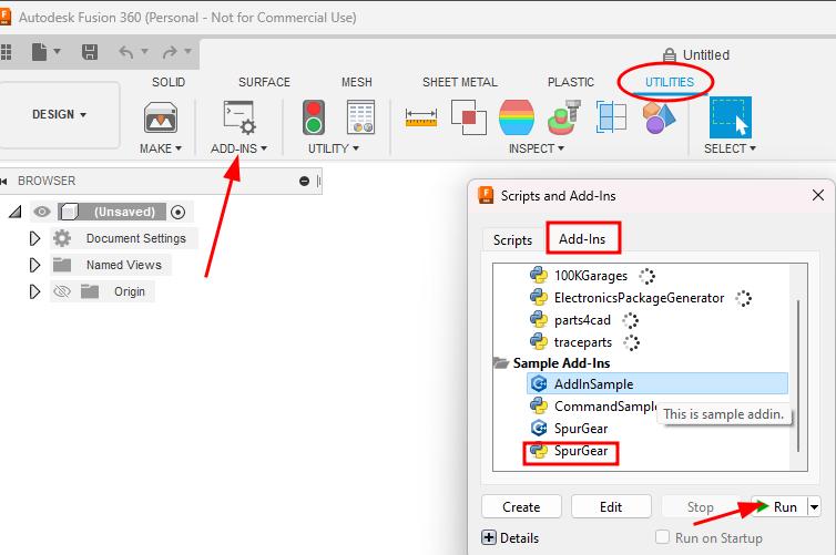
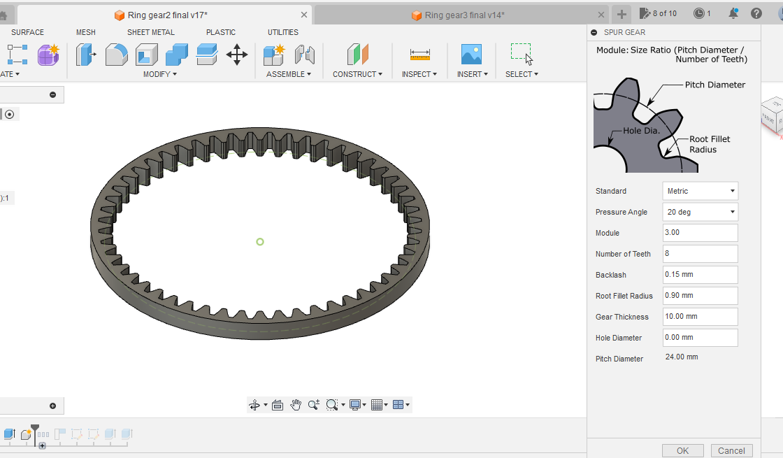
Fusion 360 has a pre-installed add-ins for spur gear. To design spur gear go to ->> add-inn ->> Utility >> ADD-INNS >> Scripts and Add-Inns >> Add-Inns >> Spur gear >> Run.
The message pop up saying gear add-in is added in the create drop down list ->> click OK.
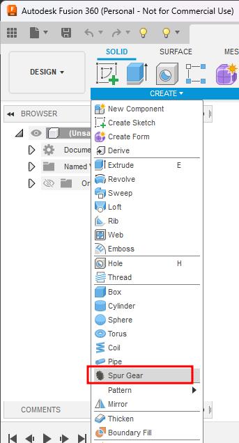
I went back to Solid tab and under drop down list there is Spur gear option.
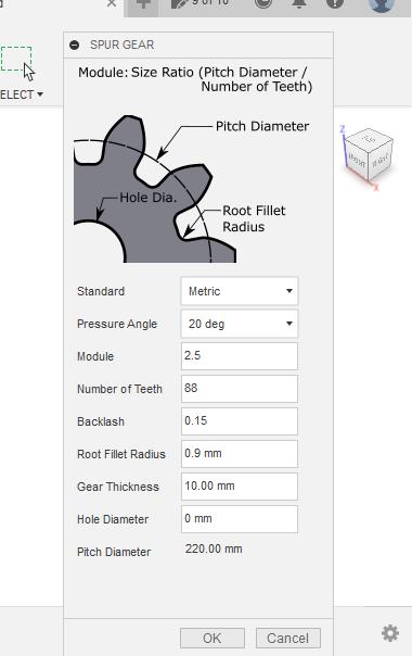
Some important terminology
- Pressure angle: The pressure angle is the angle at which the force is applied between the teeth of gears.
- Module: Ratio of gear’s pitch diameter / number of teeth.
- Back lash: Clearance between two mating gears.
- Root fillet radius: Radius where the gear teeth meet to root or the base of the gear. Always keep less than 1mm.
- Pitch diameter: Diameter of the gear used for spacing the gears
Module and the number of teeth determines the pitch diameter.
I used the settingas below and clicked ok.
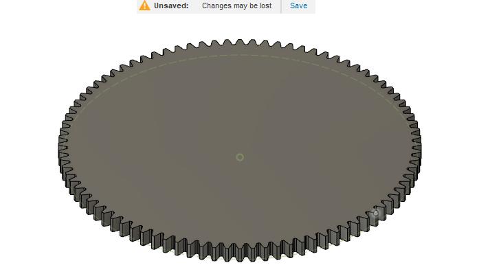
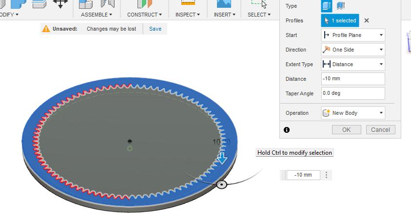
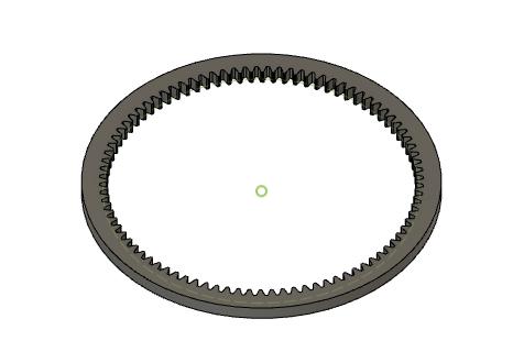
I want a ring gear so I will create a sketch on the top and the extrude the body as a New body. To get only outer ring I will extrude cut the inner part of the gear.
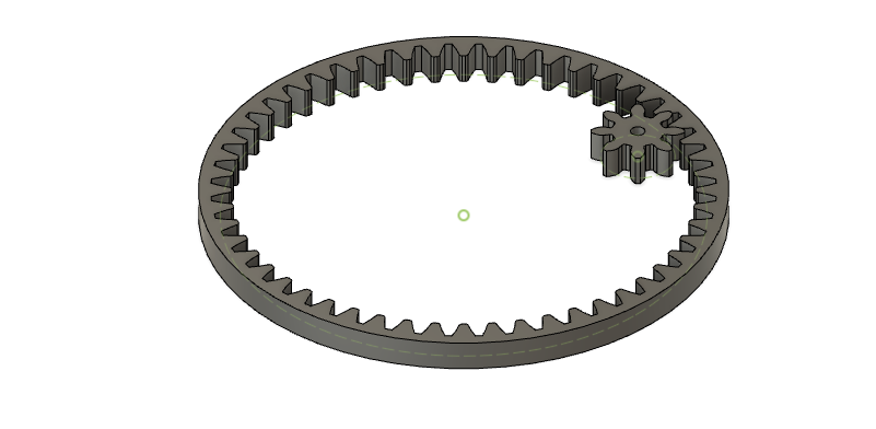
Drive gear
The drive gear is small one which will be attached to servo and drive the ring gear. I used 8 teeth and same module(3). If i use different module it is not getting meshed.
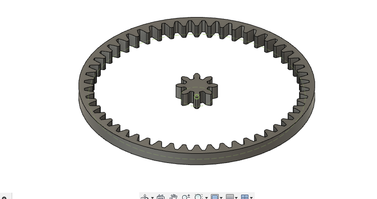
I moved the gear to make meshed with the ring gear. I made a hole at the center of the drive gear to fit the servo motor.
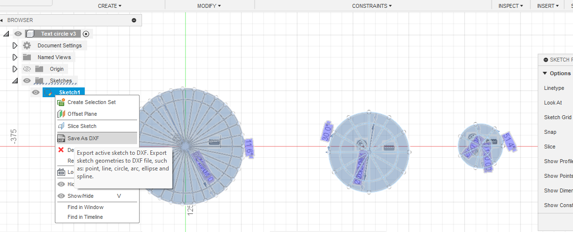
Exporting the .dxf file for laser cut.
I projected the body and the sketch gets created. On the sketch right click and saved the dxf file.
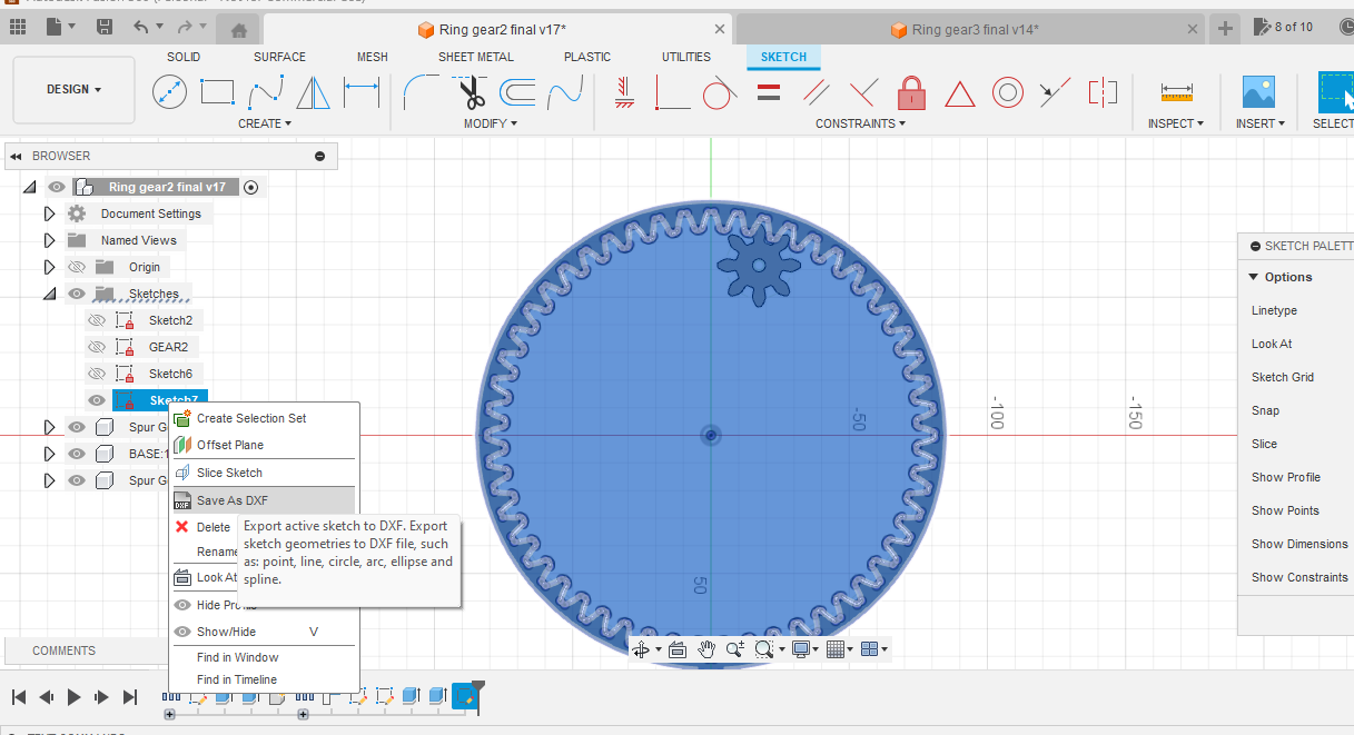
The dxf file I exported directly from fusion 360 is getting distorted in Inkscape I used online file converter to convert dxf to SVG which works perfectly.
Writing Text on rings
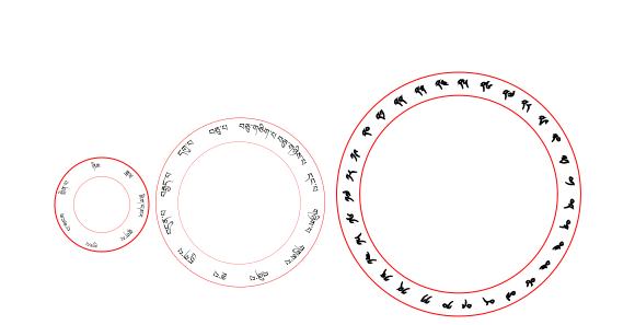
Before writing the text this is how I divided the 360 degree circle into different sections of month, day and date. I saved the dxf file from sketch.
-
For date I divided 360/number of days(31)= 11.6 degree. I drew only I section and rest of the section I created using circular pattern.
-
For month I divided 360/number of days in each month(12)=30 degree.
-
For the week days I divided 360/7=51.4 degree.
Working on Inkscape
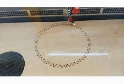
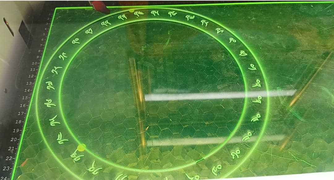
For cutting the rings and the bigger gear I used Laser cutter. I typed the letters in local language and adjusted the stroke size to 0.001mm for the ring to cut.
Firstly I want to check the mechanism without cutting everything into final, so I cut it on plywood as I don’t want to waste the material.
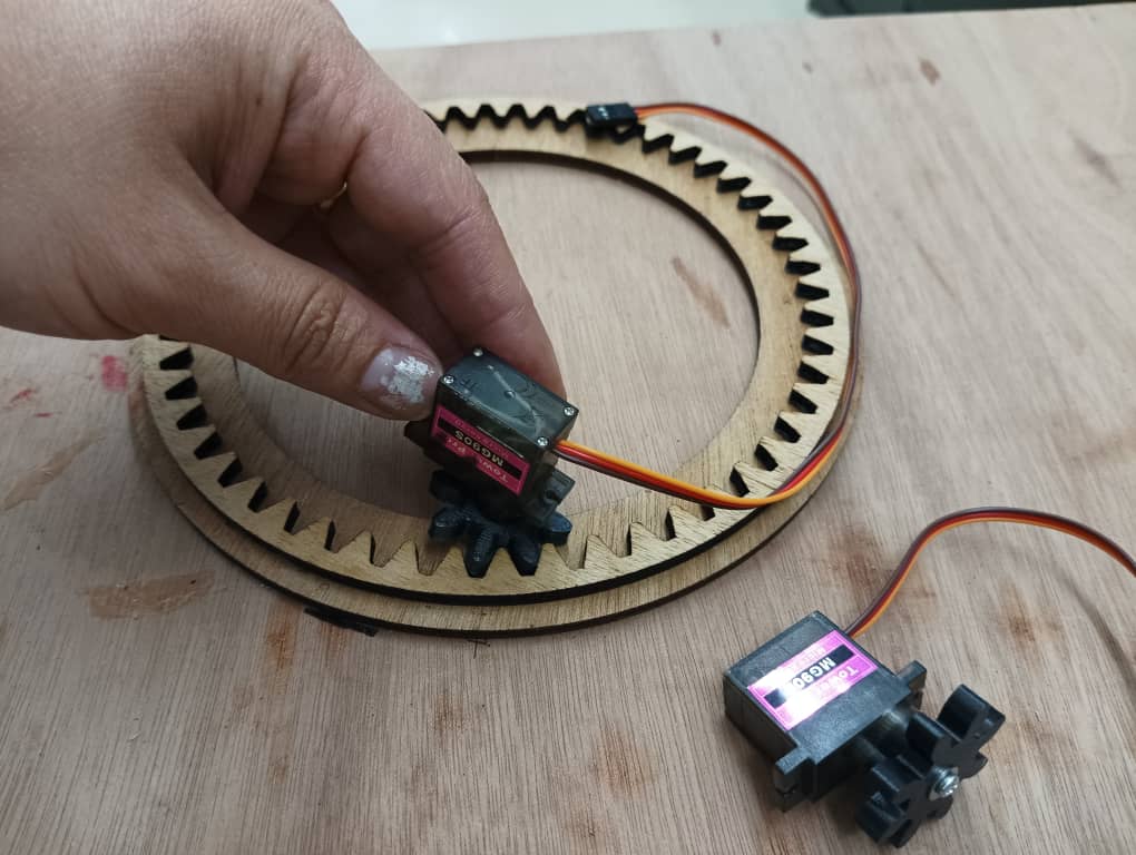
I did a 3D print for the drive gear and mounted on the servo motor.
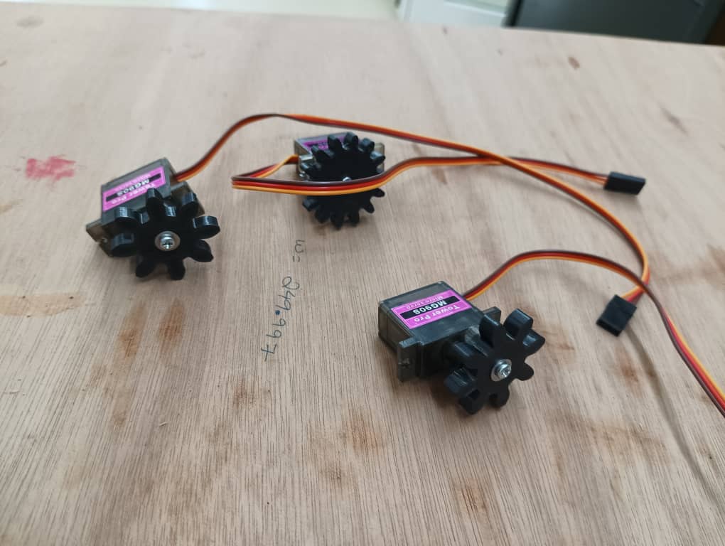
I cut the driven gears on laser cut and pasted on the back side of the ring using glue. I did 3D printed the drive gears and attached to the servos.
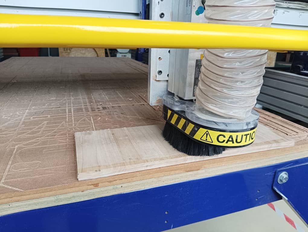
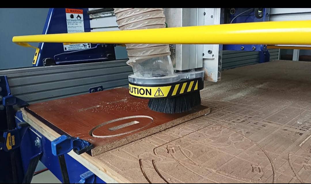
Working on shopbot
I used hardwood to make back stand and milled in CNC router.
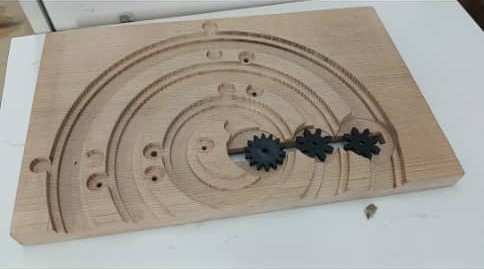
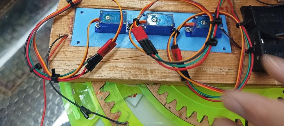
I used the bearings as a roller and mounted the servo motors from the back. I did a sanding with a sand paper for the smoothness around the rings and the slot as well.
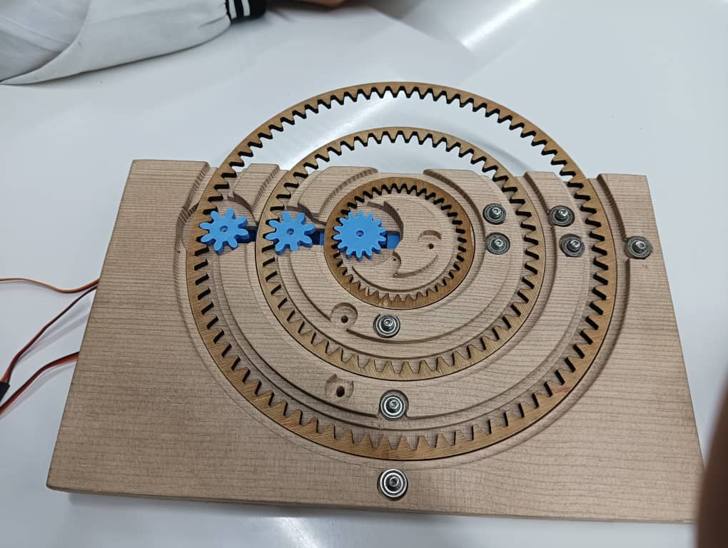
After assembling the parts and tested the mechanism.
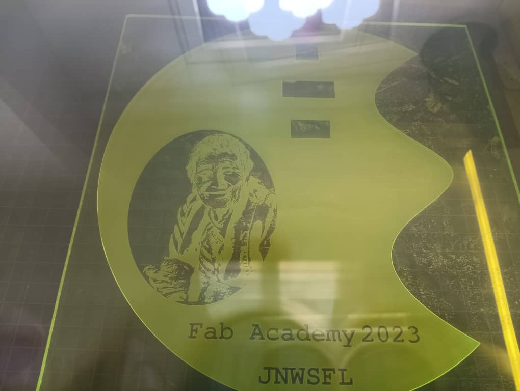
For the final rings I engraved on transparent acrylic to reflect the light.
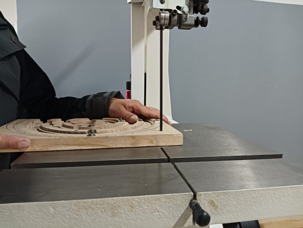
I attached the gears behind the rings. For the back stand I did not cut it on shopbot because the wood was small and no spcae to clamp. I had to cut it in band saw and do the sanding.
Front cover
For the front cover I engraved grandma’s picture and also used LED to illuminate during night hours.
I cut the particle board for base in shopbot did sanding to remove the sharp edges.
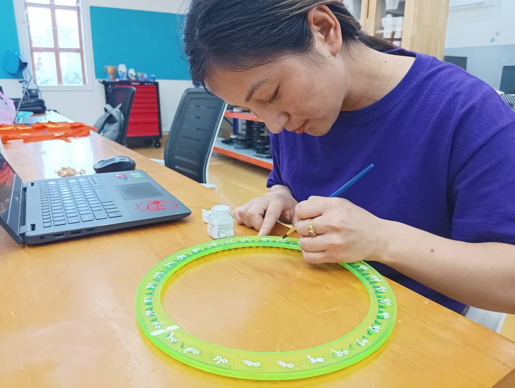
Finally I did a paintings on the wood parts and the text to make it more visible.
Electronics Design and production
As I am complete beginner in electronics I failed many times in designing, milling and programming the board. I attempted many times to make my final board work.
I made two PCB board for my final Project
Designing LDR sensor board
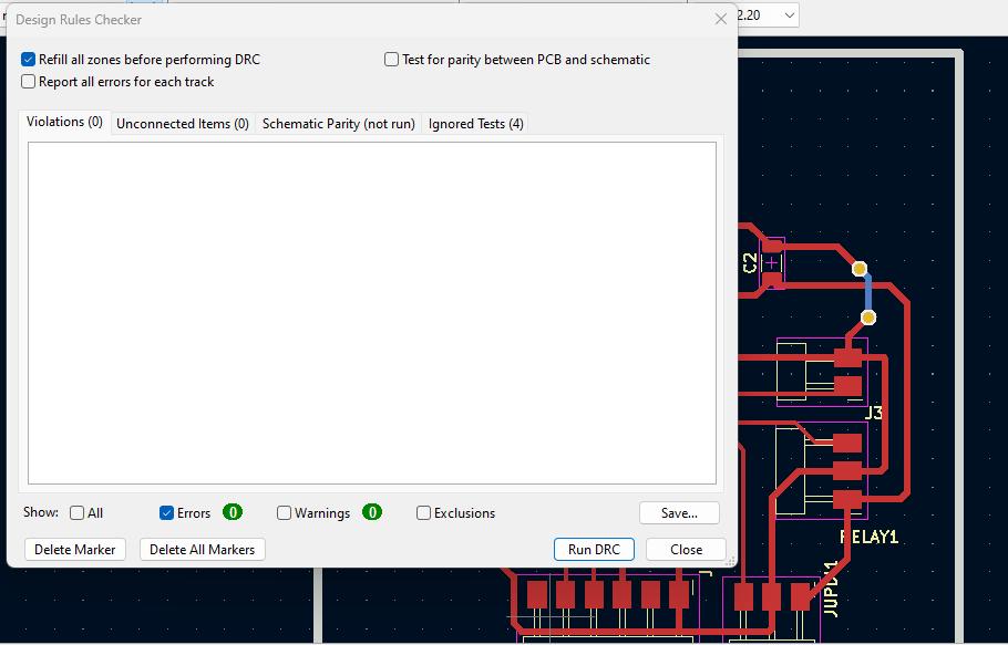
I designed my board for controlling LED with LDR sensor. I am happy that this time I did not get error when I run ERC and DRC. Only there was warning with the grid settings. Since my kicad is 7.0 version I couldn’t get the exact setting of grid as I used the older version.
I run the design rule checker and it was fine.
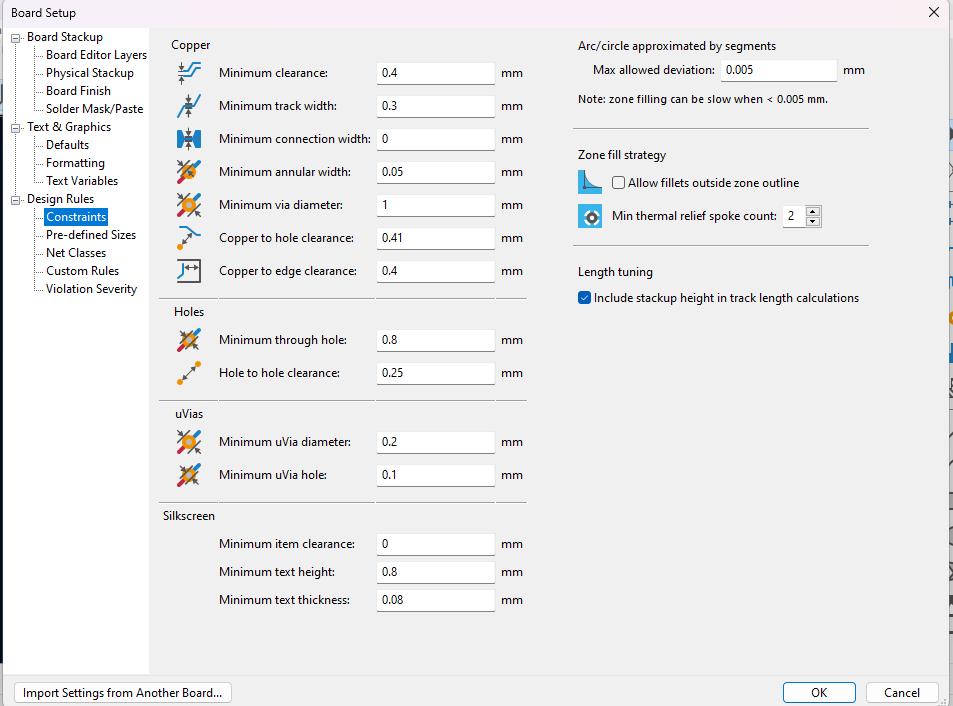
Before drawing the traces I did a board setup. For this I referred the video which is taught us during FabZero session by Fran and Sibu during our lab setup last year.
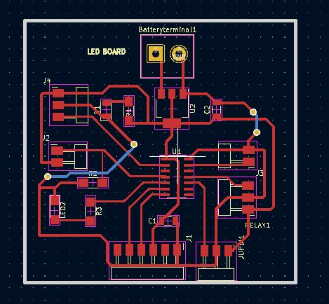
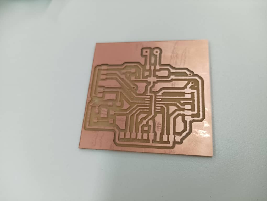
This is my PCB Layout.
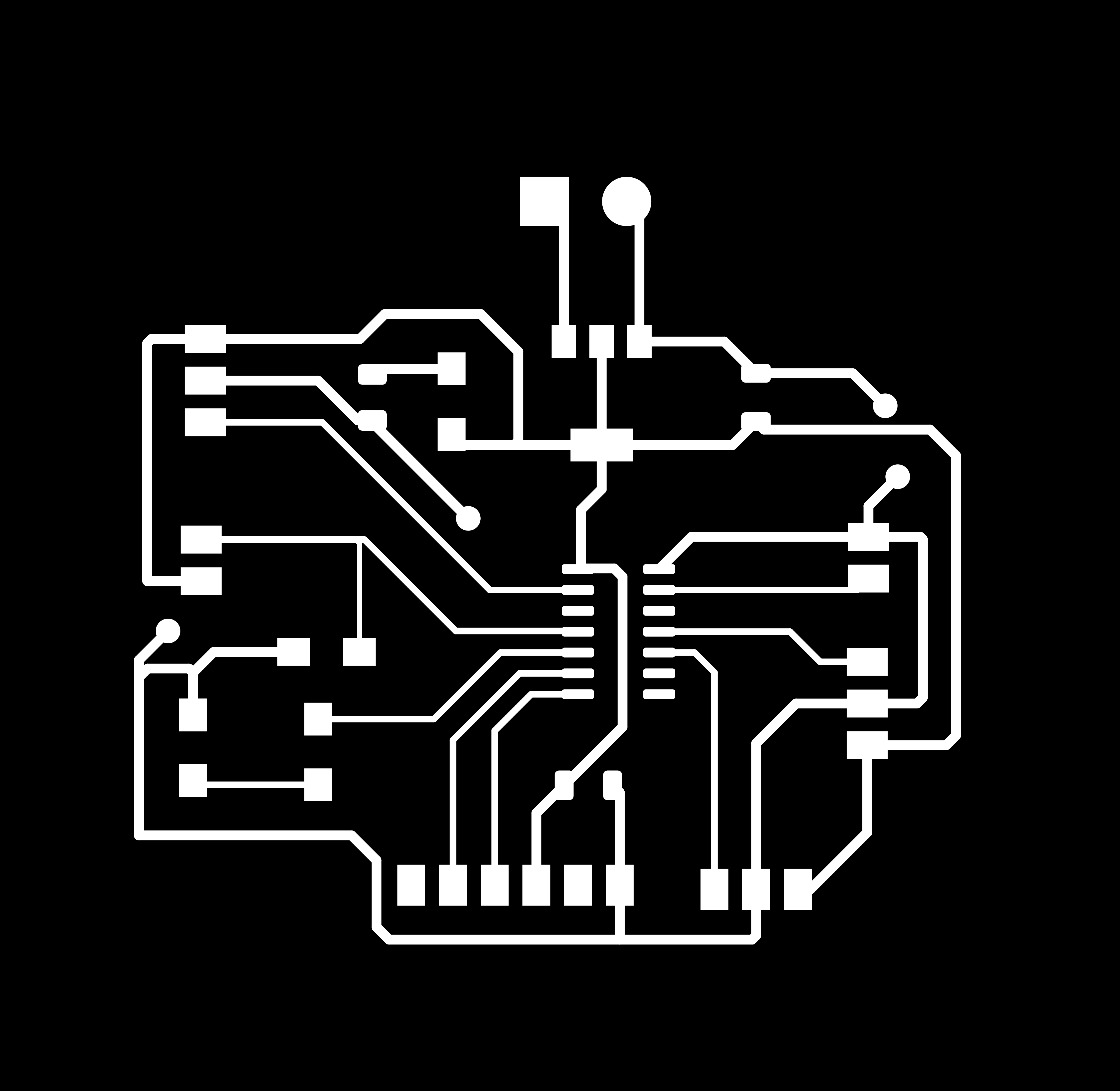
I exported the file SVG file and used INkscape to convert it to PNG file.
Here is the PNG file for my board.

Milling and soldering the components.
I milled the board in SRM 20 using end mill 1/64 inch for traces and 1/34inch for edge cut milling.
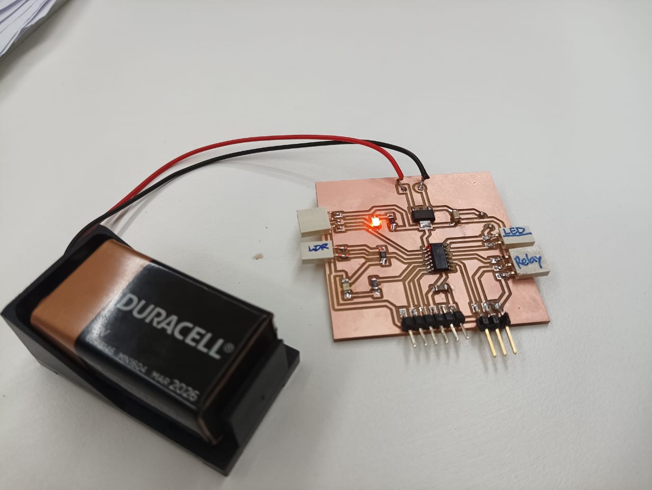
Testing the board
To test the led board I uploaded the blink example code from IDE and it worked.
Then tested the led strip controlled by relay and it worked. The code is same as blink led code example. I replaced blink led pin to the relay pin.
    void setup() {
    pinMode(8, OUTPUT);
    }

    void loop() {
    digitalWrite(8, HIGH);
    delay(1000);
    digitalWrite(8, LOW);
    delay(1000);
    }
LDR Testing*
I want to use the white mono colour LED and it is 12V. Since from my board I can provide only 5V I used external supply to LED and connected to the relay.
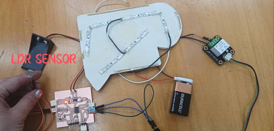
On my board I connected LDR sensor to PA6(2) which is photoPin and I defined the relay pin in place of LEDpin. I referred this and uploaded the code below and it worked.
const int LEDpin = 8;
    const int photoPIN = 2;

    void setup() {
    // initializing the serial communication:
    Serial.begin(9600);
    pinMode(photoPIN, INPUT);
    pinMode(LEDpin, OUTPUT);
    }
    void loop() {
    // read the sensor:
    int sensorStatus = analogRead(photoPIN);
        Serial.println(sensorStatus);
    // now, it will check the reading or status of the sensor is > 200
    // if it is, LED will be HIGH
    if (sensorStatus >200)
    {
        digitalWrite(LEDpin, HIGH); // LED is ON
        Serial.println(" LED is ON, status of sensor is DARK");
    }
    else
    {
        digitalWrite(LEDpin, LOW);
        Serial.println(" ***************");
    }
    }
Designing board for Servos
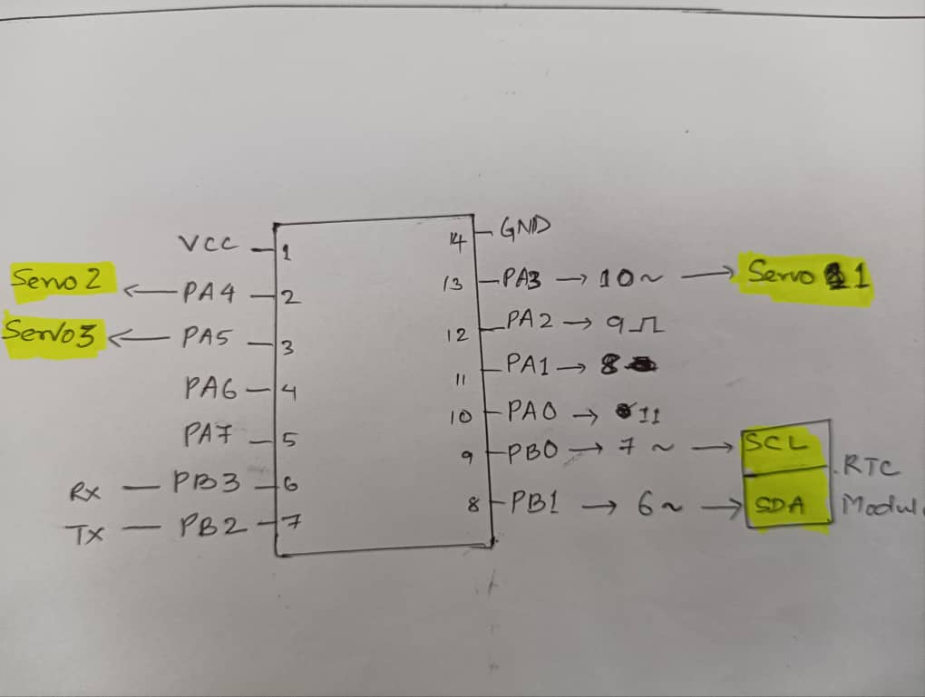
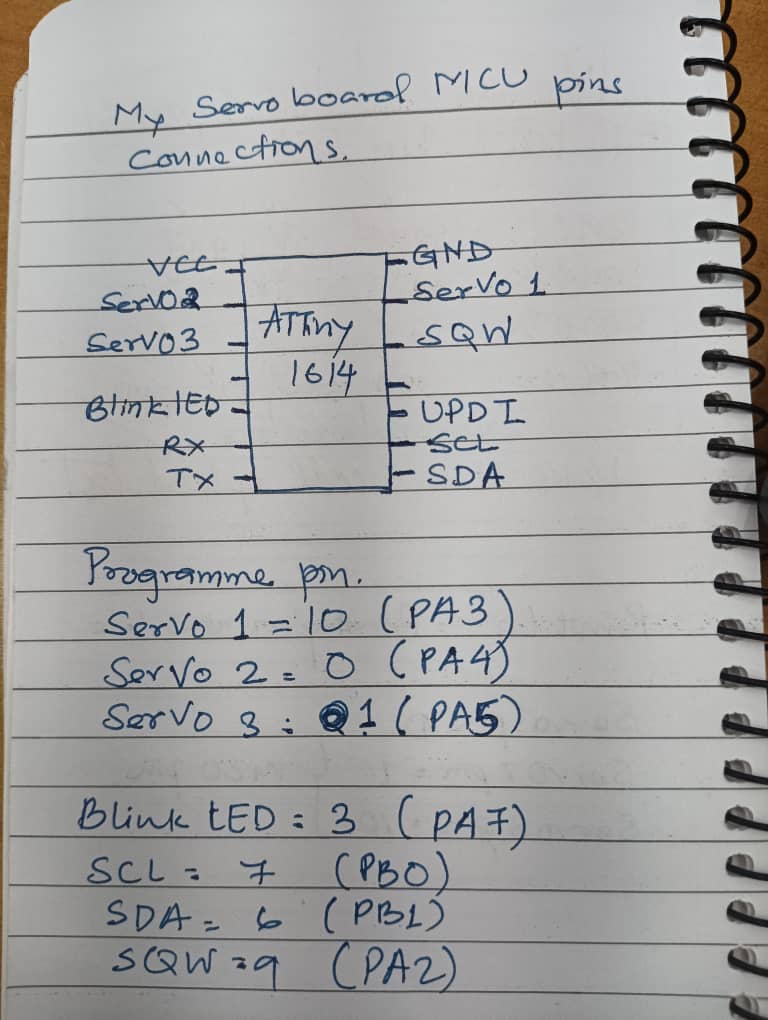
To design a board for the servo motors I need PWM pins. For three servo motors I need three Pulse Width Modulation pins form ATTiny 1614. I studied the pins as below. In ATTiny 1614 there are 6 PWM pins. This is also one important reason to split board into two. If In use single board there will be specific pin shortage.
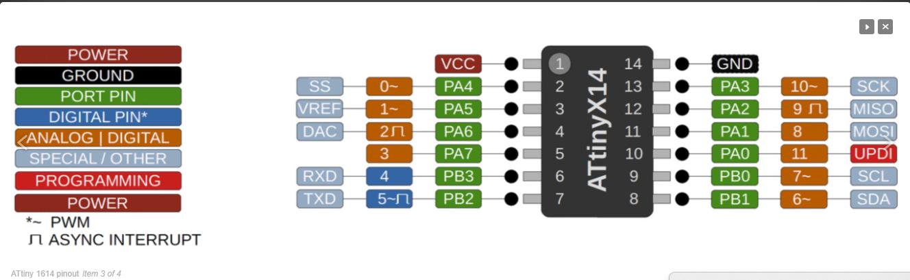
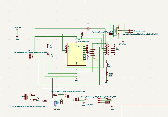
This is my Servo location on MCU pins.
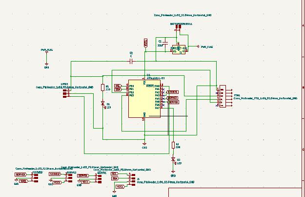
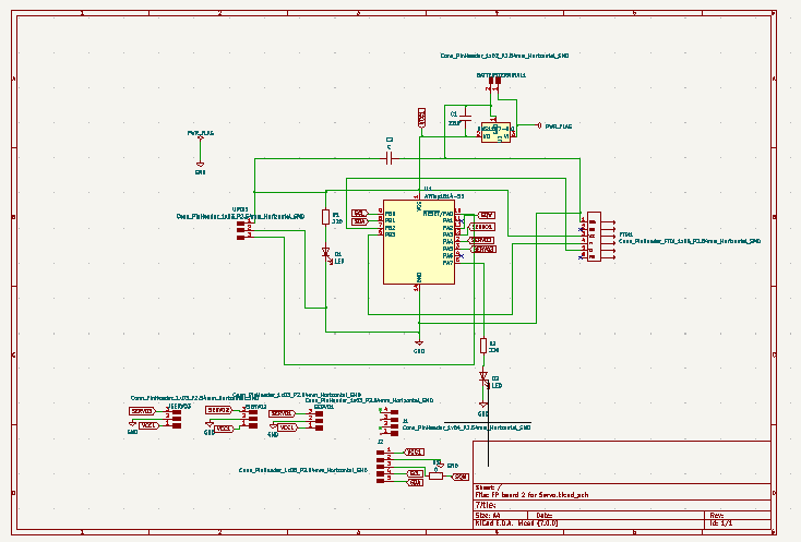
This is my schematic diagram.
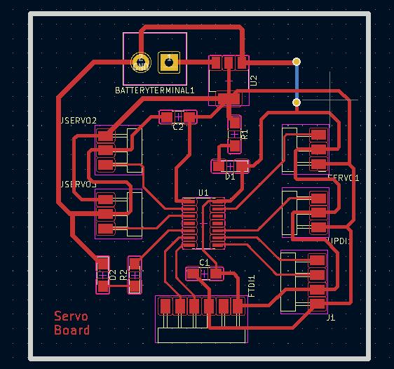
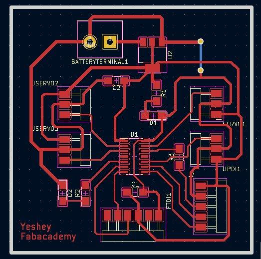
Here is my PCB layout of board for Servo motors.
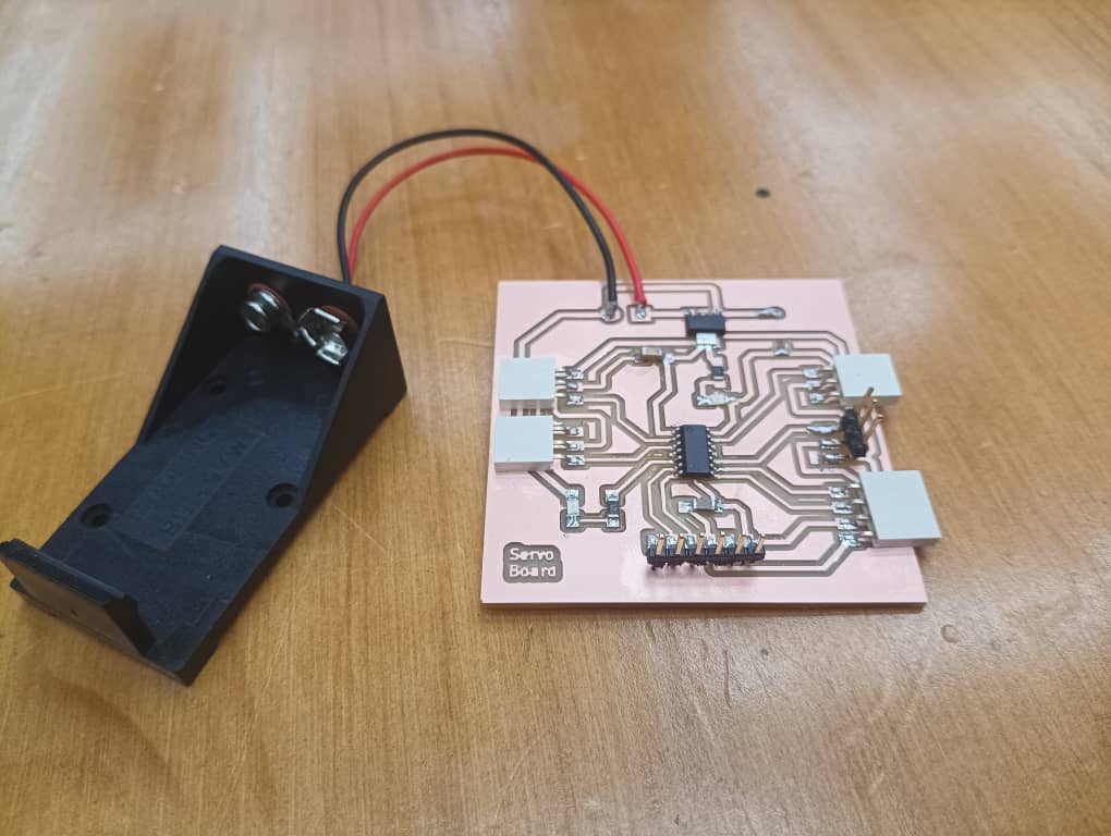
Milling the Servo Board
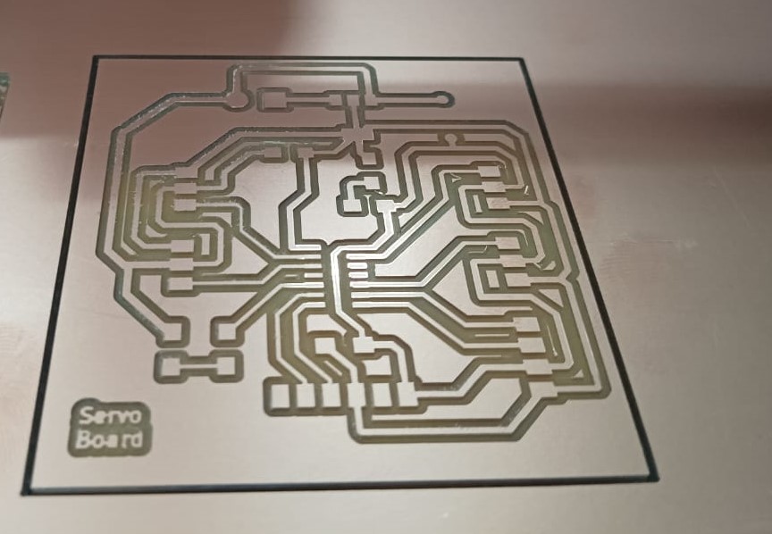
 .
.
When I power my board I noticed the MCU pins are receiving the power and when I tried uploading the programme it says UPDI initialization failed.
 .
.
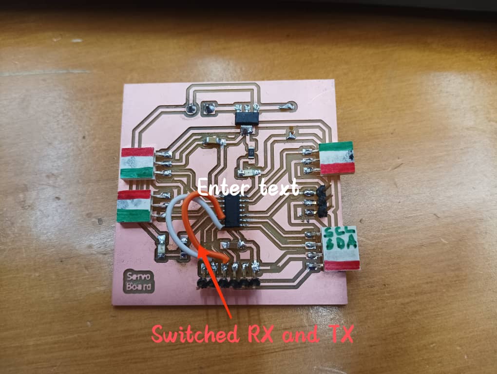
Since the pads beneath the LED was giving the connections I desoldered the board and removed some pads beneath the components that may cause the bridging. I also made a mistake in RX and TX is connection. So i used a jumper wires to switched RX and TX and soldered all the components again.
 .
.
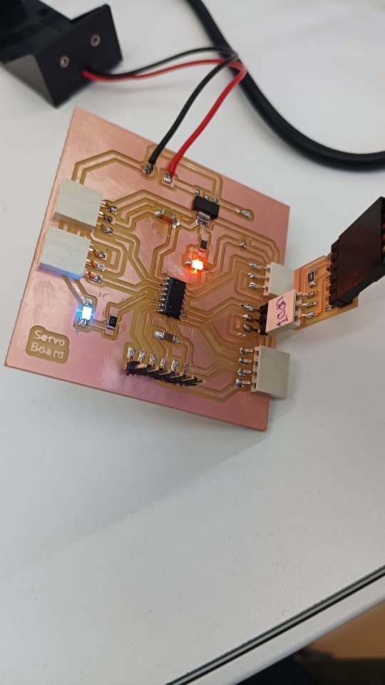
I tested the board and it worked. I did with blink LED test, servo motor taste and with RTC module. The testing part is linked here.
2nd Version of my board
Since I need a alarm interrupt function to trigger the servo motion I need to added one more pin on my board connected to SQW of RTC module.
I redesigned the board because I need a extra pin for RTC module for integrate alarm function. This will be my final board.
 .
.
 .
.
Here is the PNG file for Traces and edgecut.
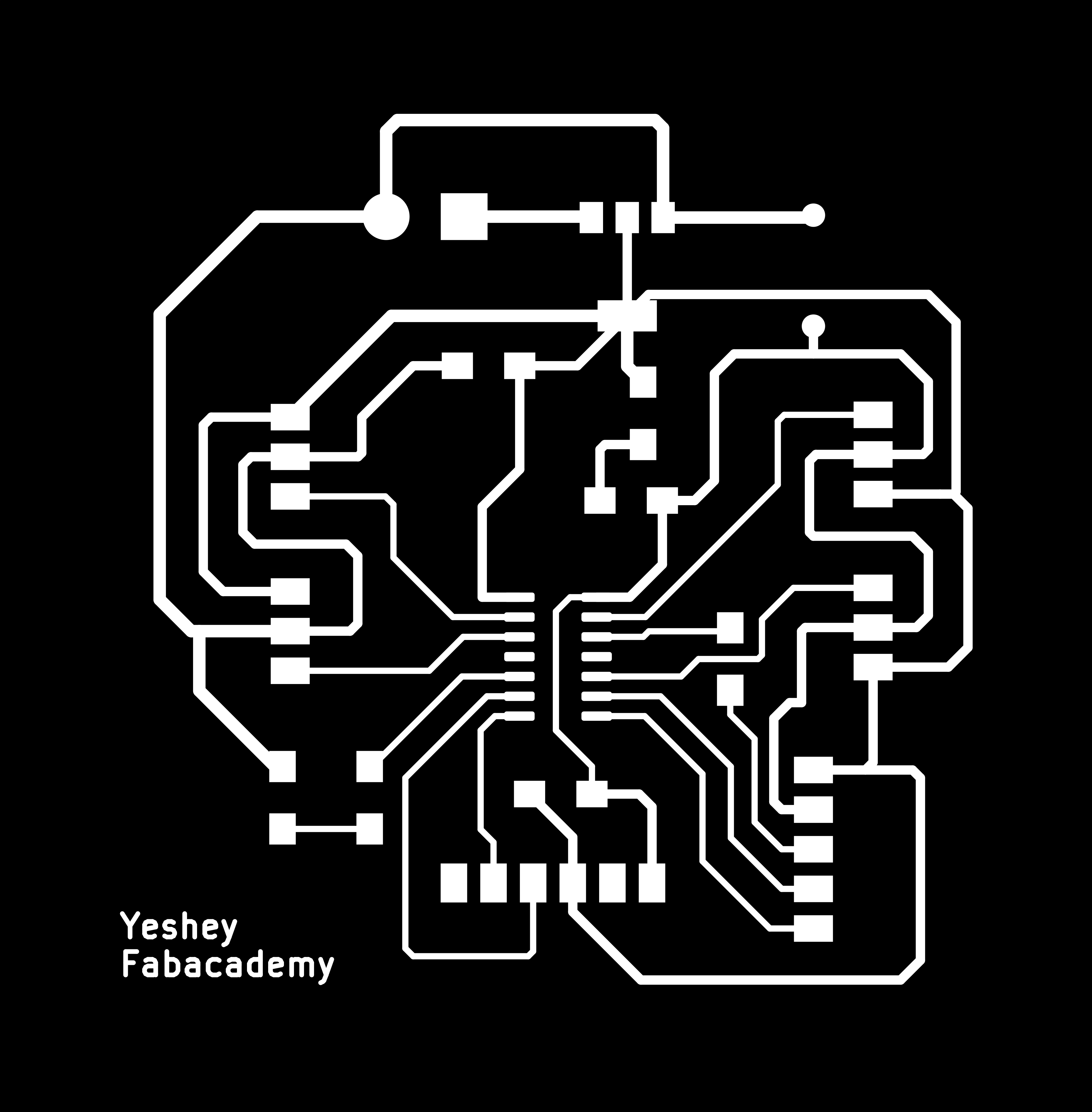
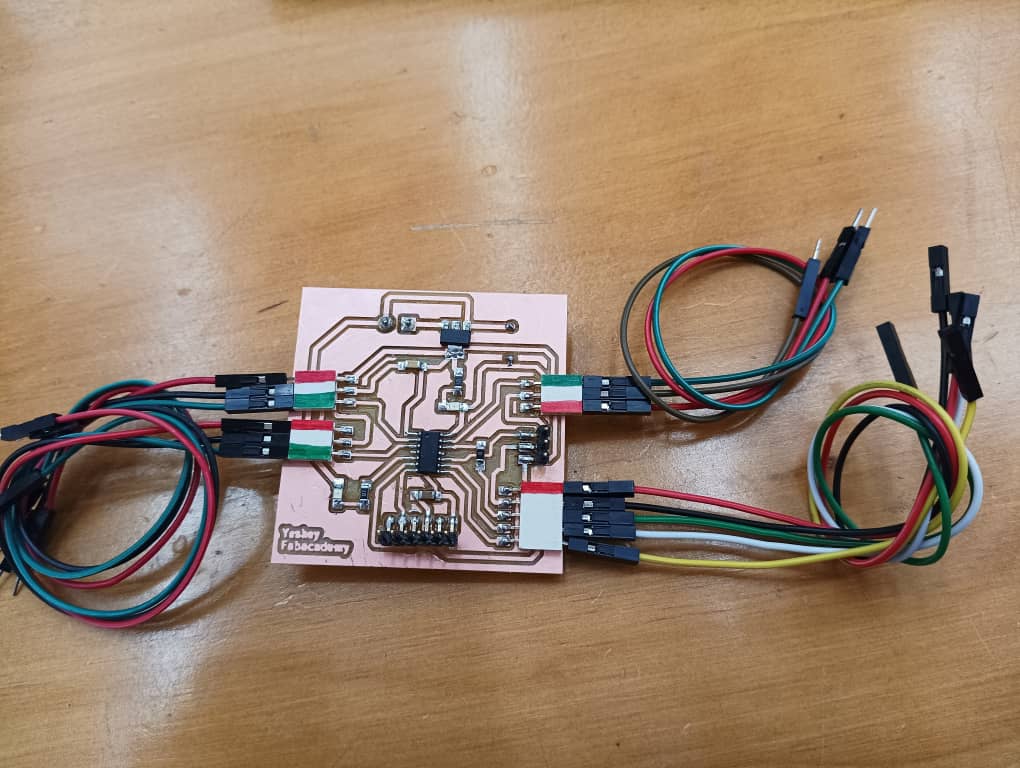
I milled the board and soldered the board. THis time our solder us better and looks shinny as Guru Rico taught us to us flux which helps the lead melt better and shine.
Here is the hero shot of my board.
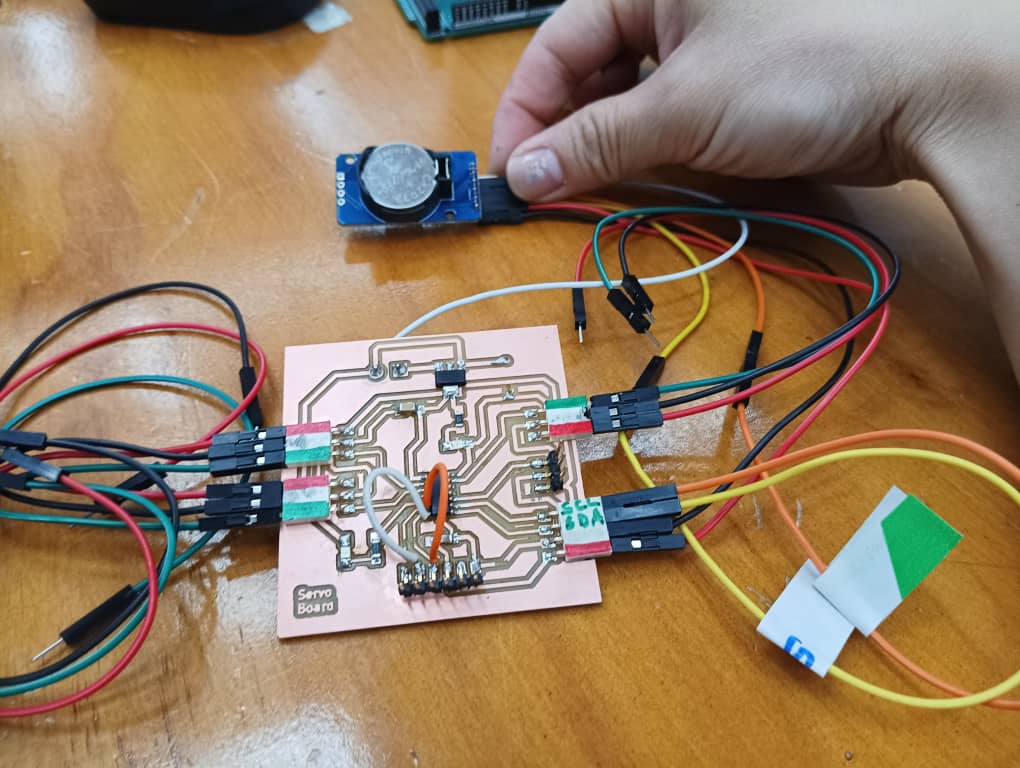
Testing my servo board
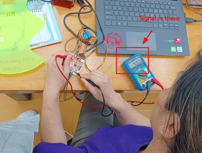
Guru Rico helped me with codding to test the board with the following code and it worked. For this I did not use servo motors instead I used multimeter to see the signal lines and it worked. In the signal lines it shows 4.9V when the signal is passing.
    // Yeshey Wangmo's FP board pin test program

    // by Yeshey Wangmo & Rico Kanthatham, Fab Academy 2023, Bhutan


    #include <Servo.h>
    Servo myservo;

    // Variables to represent all INPUT and OUTPUT pins on the Final Project Board
    int ledPIN = 3;
    int servo1 = 0;
    int servo2 = 1;
    int servo3 = 10;
    int sclPin = 7;
    int sdaPin = 6;
    int pos = 0;

    // the setup function runs once when you press reset or power the board
    void setup() {
    Serial.begin(9600);

    pinMode(ledPIN, OUTPUT);

    myservo.attach(servo1);
    }

    // the loop function runs over and over again forever
    void loop() {
    digitalWrite(ledPIN, HIGH);   // turn the LED on (HIGH is the voltage level)
    Serial.println("LED ON");
    delay(2000);                       // wait for a second
    digitalWrite(ledPIN, LOW);    // turn the LED off by making the voltage LOW
    Serial.println("LED OFF");
    delay(1000);                       // wait for a second

    //Use the code below to check if individual signal pins receiving 5V...change the name of the pin receive HIGH signal
    digitalWrite(servo3, HIGH);   // turn the LED on (HIGH is the voltage level)
    Serial.println("Pin ON");
    delay(3000);                       // wait for a second
    digitalWrite(servo3, LOW);    // turn the LED off by making the voltage LOW
    Serial.println("Pin OFF");
    delay(3000);                       // wait for a second

    //code for testing servo motion
    for (pos = 0; pos <= 180; pos += 1) { // goes from 0 degrees to 180 degrees
        // in steps of 1 degree
        myservo.write(pos);              // tell servo to go to position in variable 'pos'
        delay(15);                       // waits 15ms for the servo to reach the position
    }
    for (pos = 180; pos >= 0; pos -= 1) { // goes from 180 degrees to 0 degrees
        myservo.write(pos);              // tell servo to go to position in variable 'pos'
        delay(15);                       // waits 15ms for the servo to reach the position
    }
    }
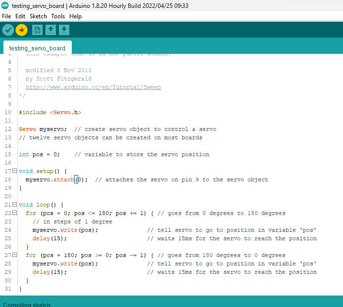
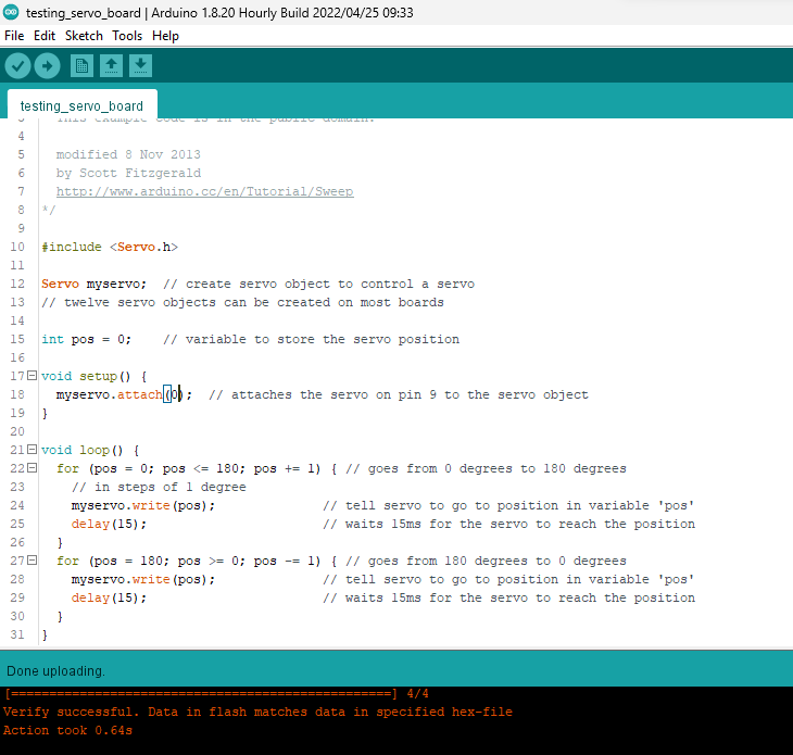
I uploaded the IDE example servo sweep code as below to see whether my board works aor not. It worked.
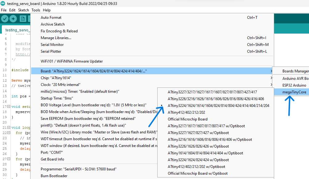
- Select the board
-
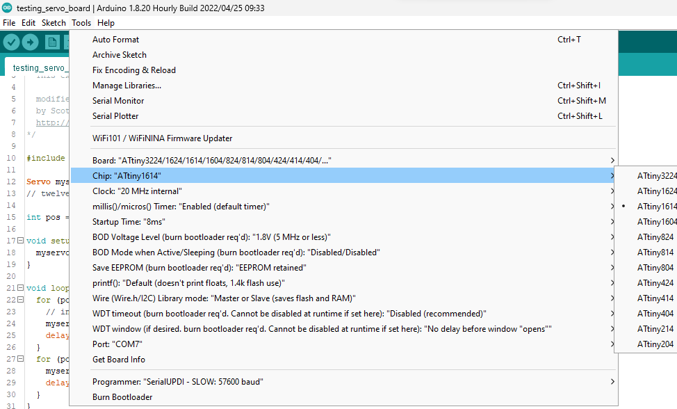
Select the chip
-
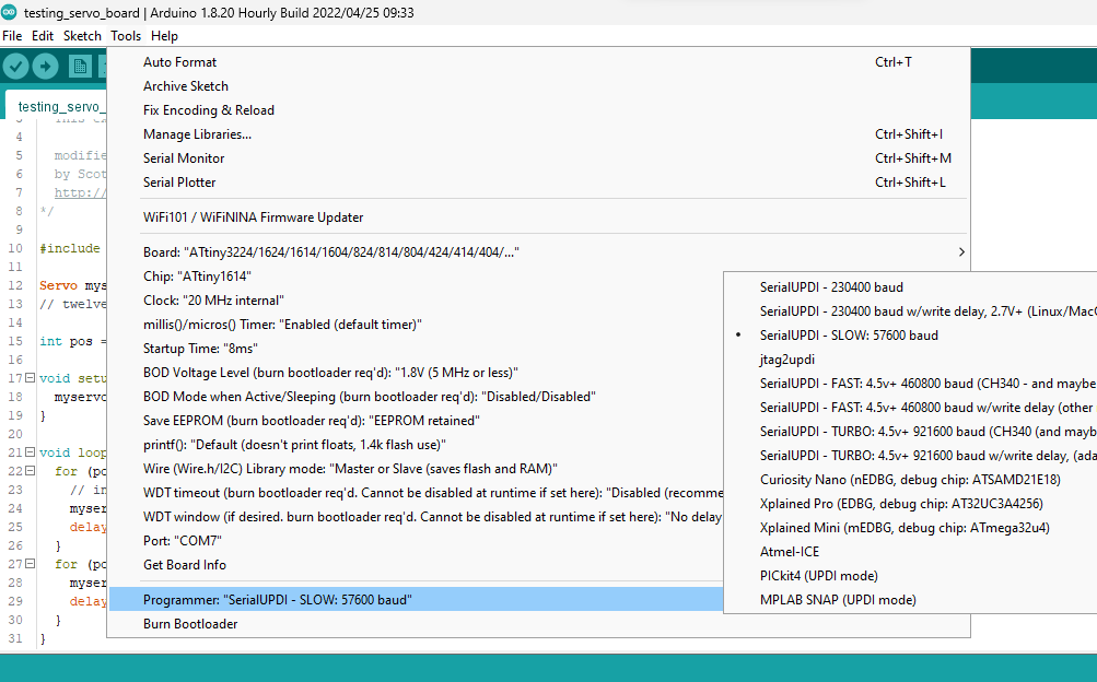
Select the programmer
-
Select the port
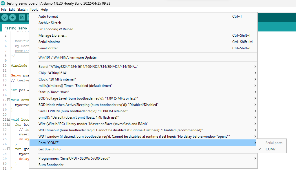
-
Compile and verify the code
- Upload the code.
Programming and Integration
Firstly i referred the datasheet of DS3231 and I link it here
I downloaded the ds3231 RTC module library in arduino. The link is here.
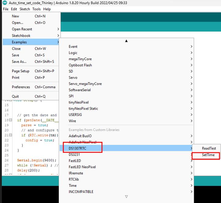
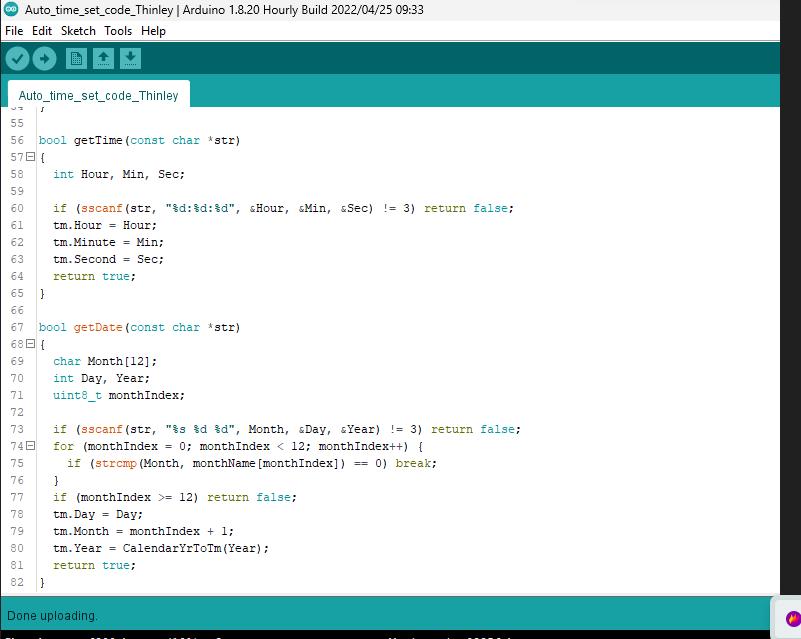
Firstly I learned how to set time and the code is here.
I connected the RTC on my board as below, connected the SDA, SCL and SQW pins of RTC to the SDA,SCL pins on MCU respectively.
For the code I used the time set example code from library to set the time and uploaded on my board.
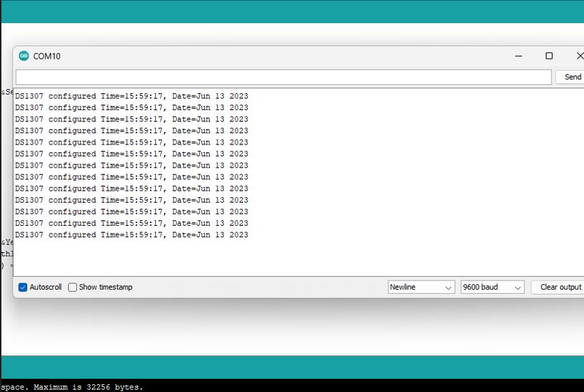
To check whether the time is set or not I did serial monitor. My RTC time got set successfully as shown below.
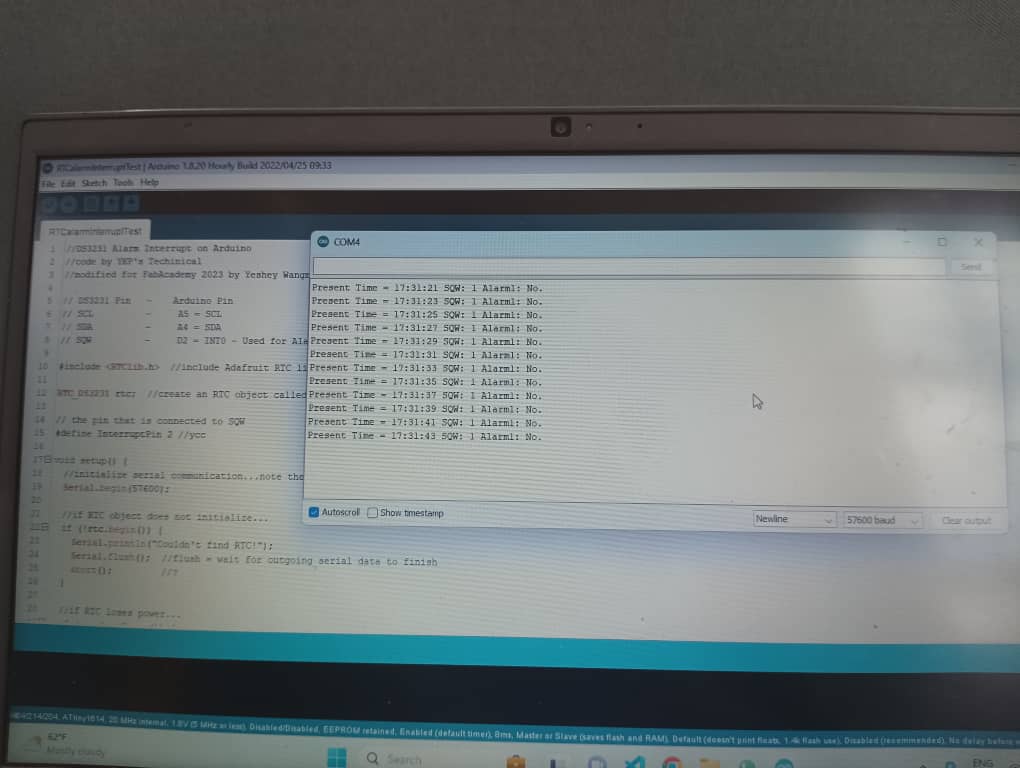
I uploaded a code to set a alarm to trigger my Servo’s motion in every 24 hours for day and date and did a check in serial monitor as shown below, when there is no alarm it is stating as “NO ALARM”. When the time reaches to 12:00 might night there will be alarm and the servo rotates.
License
Creators can apply a Creative Commons license to their work if they want to give other people the rights to share their works. Creative Commons offers several types of licenses with features that offer different levels of protection.
I go for Attribution- NonCommercial-Sharelike license.


Here are the here are the license terms:
I accept other people for using and sharing my final project materials. I made this project not for commercial purpose and I made it is mainly to make something with my hand to learn more on digital fabrication. This is my first time programming electronics, indeed a learning platform for me.
Future Plan
- I want to make it chargeable.
- I want to integrate output speaker module
- I need to refine the PCB design into one board.
Conclusion
I would like to thank our Guru Rico and mentor Zina for whole heartedly reaching out on us to completed the final project, without their continuous support this would not be possible. Also, I would not forget to thank Sir Junk for being our wonderful global evaluator.
Most importantly, graduation ain’t going to be my end of this journey, I will keep on adding my new learnings in this page.
Thank you