'Two strong men will move a heavy stone. Two bright lawyers will not agree about the meaning of a word.'
African Proverbs
Mechanical and Machine Design
Group Assignment
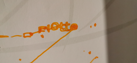
For this assignment, I have decided to work on a X-Y Plotter with the capability for vinyl cutting, which would help me to finalise my week 3's assignment. The task includes the following:
Collaboration and responsibility
For this assignment. I and Baptiste Lardais joined forces to work on a XY plotter with the compatibility of a vinyl cutter. To execute this task, we drew inspiration from the job of Nadya Peek.
Baptiste was reponsible for the CAD designing of our Plotter. While I was responsible for building the physical machine as well as the documentation part of it.
Together, we virtually tinkered on fixing issues that arose during the assembly phase of the project.
Plotter
An X–Y plotter is a plotter that operates in two axes of motion ("X" and "Y") in order to draw continuous vector graphics. A plotter produces vector graphics drawings. Plotters draw lines on paper using a pen.
List of Components
Below are the list of components used for this task.
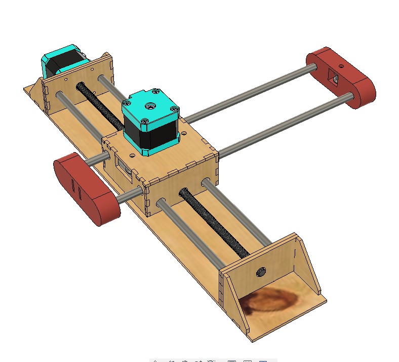
Mechanical Design
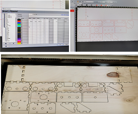
The pictures below shows the tremendous design job done by Baptiste
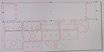
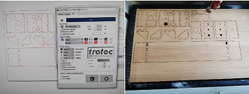
After this, we proceed with the laser cutting part of the model.
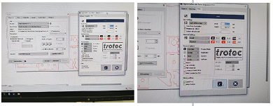
To do this, we used Trotec Speedy 100. We opened the file in Corel Draw, made some necessary gymnastics and converted the files to the format understood for cutting.
Then we transferred the job to the JobControl software of Trotec Laser cutter. Set the necessary parameters for the job.
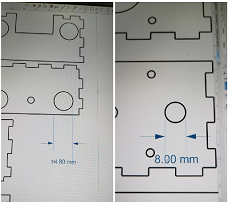
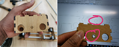
After the laser cutting, it became apparent that we remotely needed more than 2 cups of coffee to remain productive. Why? because of the mistakes depicted in the pictures below:
The files were not properly converted to the DXF format, so this altered the dimension of the job. Instead of 80mm, the nex design was so generous that it gave us 106mm. So, we went back at it, and made necessary modifications and now the job looks ok. Hope no other issues will arise now.
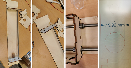

We live to fight another day!
Come morrow, we went back at it. After Baptiste sent the edited design, then we proceeded to laser cut it again. The first thing we did was to do a pair review to ascertain whether everything is as should be. We did a measurement on Crórel draw to see whether the dimensions are right.
After this, we cut the plywood. Using the same parameter set for cutting it the previous day.
It is safe to say that we can now proceed with the assembly of the machine's frame.
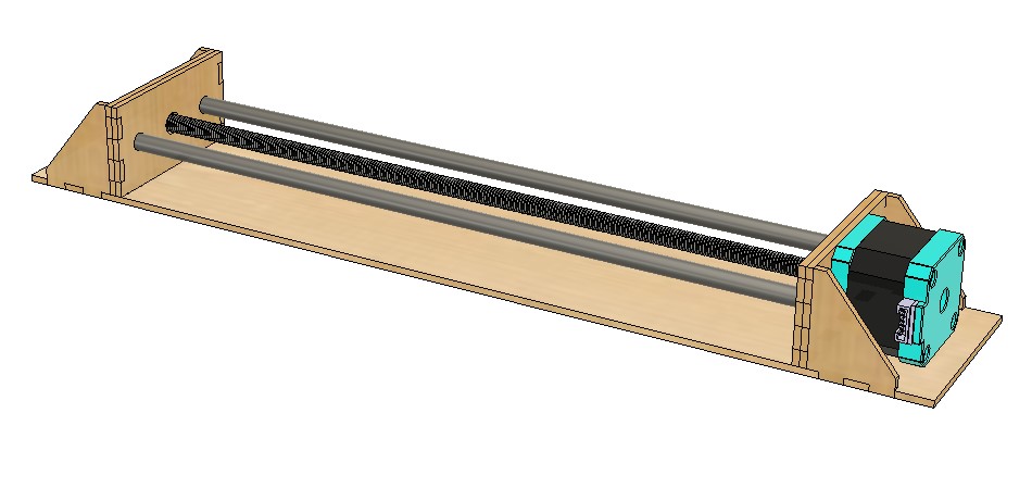
Machine Design
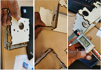
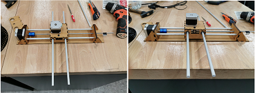
The assembly has started, and below you will find pictures of the progress with some explanations below.
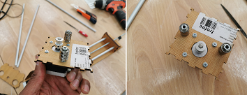
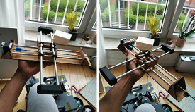
During the assembly, some issues came out that needed to be immediately resolved. This can be seen in the pictures below.
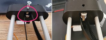
The first was that the nut to guide the threaded rod did not have a placeholder. So I modified the design to accommodate this.
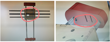
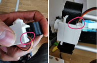
Then after fixing this, another minor issue was also noticed. The space for the cable of the servo was not created. So I manually cut the space out. However, this will be corrected in the design, and will be uploaded in the download file.
After this, the space for the GT belt in the X axis was also identified to be too tight for a smooth and free movement of the belt and bearing.
After these stream of errors, we decided to call it a day.
Below is a video showing the Y-Axis being manually moved.
The video below shows a test of the Y-Axis with the threaded rod attached.
Below is the video of the X axis manually being moved.
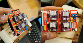
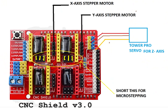
After all these, we proceeded to connecting the electronics phase of the mechanics. For this project we are using a CNC shield and Arduino Uno. You can see the picture below.
We decided to use GRBL firmware, mostly ecause of its ease-of-use. The firmware was downloaded from GRBL Download. After this, we followed the suggestions stated on GRBL Install to install it on the Arduino Uno board. This suggestions are as follows:
Now that you have installed the GLBR library on the IDE, you must compile and install the sketch GRBL UPLOAD in the Arduino board. To do that, just follow the steps stated below.
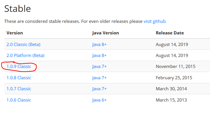
After uploading the firmware, then we downloaded the Universal G Code Sender to try move the motors. This can be downloaded from This LINK.
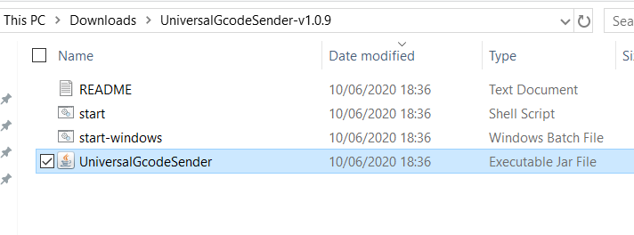
After which we extracted the downloaded file, and clicked the executable file titled 'UniversalGcodeSender'.
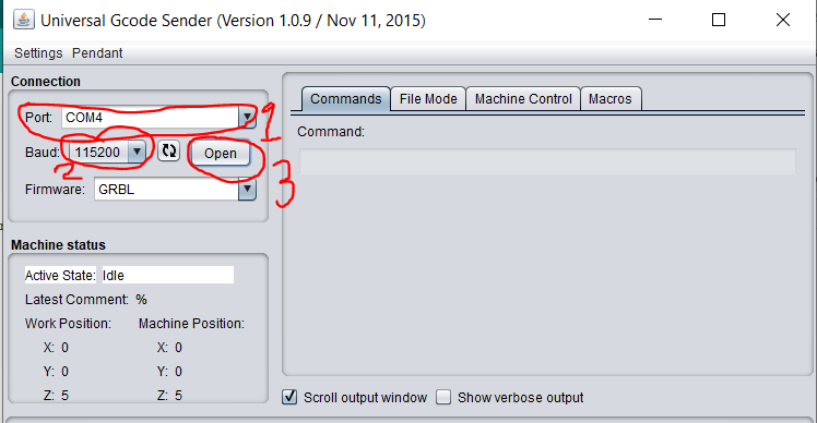
After opening it, you will see an interface like the one displayed below. Make sure you select the right port number '1 in the picture below', then select the Baud rate '115200', then click 'Open'. This will connect the plotter and the electronics together.
After this, you can make some tests to verify whether the numbers of steps per mm are accurate. If not make changes where necessary.
Setting up the Machine
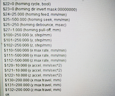
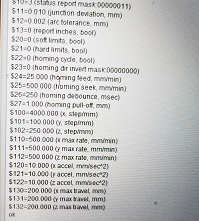
Setting up the machine has been partly sweet and sour. To do this, you just have to go to the 'Command' of the UGS and enter $$. This will bring up the parameters of the machine as depicted below.
At first, we attempted to use the calculate the numbers of steps for the stepper motors using this Website, entering the parameters of our plotter. This can be seen in the pictures below.
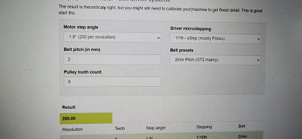
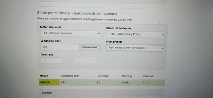
The result which we boldly entered in to the parameters of the Universal G-Code Sender

The result of this deserves its own sitcom which could be titled 'Another way to make a Stepper Motor Fly'. This is because the stepper motor acted as if it had drank Red Bull. Then we quickly unplugged the machine and started all over again.
After this, the parameter was changed to a random number 200 for X-Axis and 400 for the Y-Axis. Then we gave a command to draw a line of 10mm and it generously drew a line of 80mm. So after noticing its generosity, we calculated the new number of steps for the x axis using the formula below:
10/80 * 200
Which produced an output of 25. This we changed on UGS, and sent a new command to draw a line 10mm again. This time around, the lenght of the line was correct.
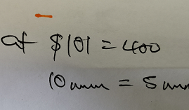
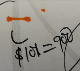
However, with regards to the Y-Axis, we sent a command for it to plot a line of 10mm, but it plotted a line of 5mm instead. So we also doubled the value of Y on UGS to 800. However, this still wasn't accurate as it plotted a line of 9mm instead of 10. Then when we tried it at 900, was everything perfect.
Final Test
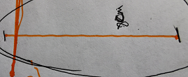
first we created a simple plot test. This looked hopeful
After this, we created a Spiral test plot to know how far we are with the project. However, we noticed some mechanical issue on the X-Axis, which created a what seems to be Noodles instead of spiral test. See the picture below.
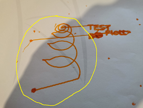
After this sprint, it became apparent that we (Baptiste and I) actually needed a big bowl of noodles more than the machine. So we left it till another day, since it was already late in the night.
We also made provision to add a servo motor to the plotter, below you will find how to connect it to the CNC shield.
Below you will find some pictures and a video showing the plotter in action.
The picture above was the first we made after being a bit certain about our progress. The one beneath was taken after, and this is the version shown in the video.

There are still so many rooms for improvements. One definitely is to get the Servo Motor working, another is to fix the limit switches for both axes.
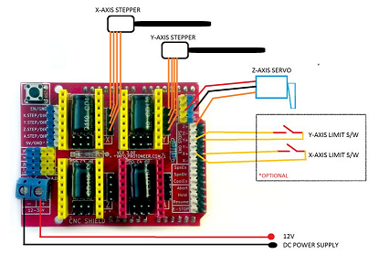
We will be using this schematic, ripped from this Website. We also used the website to set up the machine.
You can also download the files here Download Files.
You can follow the progress of the Final project HERE.