'A man of valor lacking discretion attracts to himself avoidable antagonism.'
African Proverbs
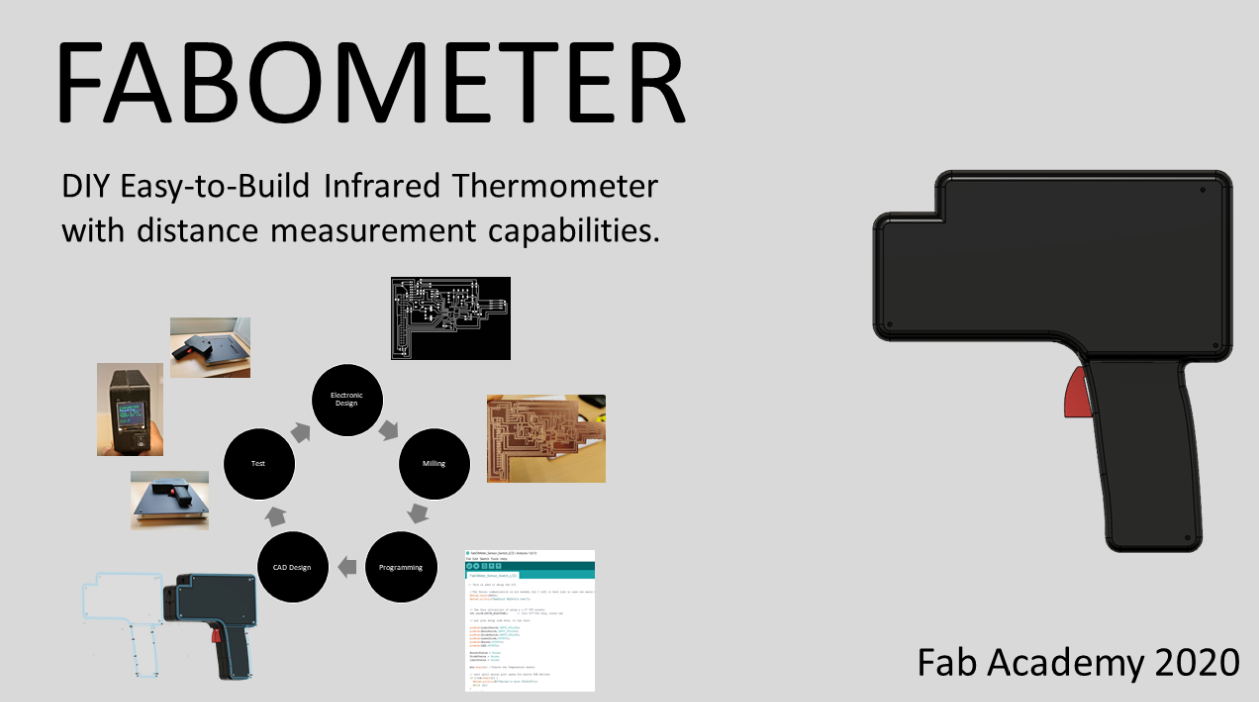
FabOMeter
Disclaimer I think I should start with a disclaimer to this name because as we all know, 'Change is the only constant thing in life.' That been said, the name might change with time, depending on the project.
Project Introduction
Since I was born, or if I could say, since the history of human kind, there has not been a virus so audacious and ferocious to keep all countries and most industries on locked down at a specific point in time. The previous virus invasions were mostly region specific or quickly contained in the affected regions (for example, H1N1 virus in 2009, SARS virus in 2003, and also the Spanish virus in 1918). However, most human got a reality check with the recent and sudden invasion of a virus with such a lovely name (Corona is something suggesting a crown) but a deadly intent. This virus invasion caught humanity offguard, except the 'Doomsday Preppers'. It literally turned a crippled social system into an antisocial system, due to the social distancing mitigation strategy developed to curb the spread of this deadly beast. Due to this development and since the purpose of Fab Academy is to churn out skilled individuals with the capability to 'Make Almost Anything'. I Babasile Daniel decided to exemplify the skills gained during this Fab Academy journey to lend a helping hand to the world by attempting to develop an Open Source Infrared (Non-Contact) thermometer, which can be used to check the temperature of people.
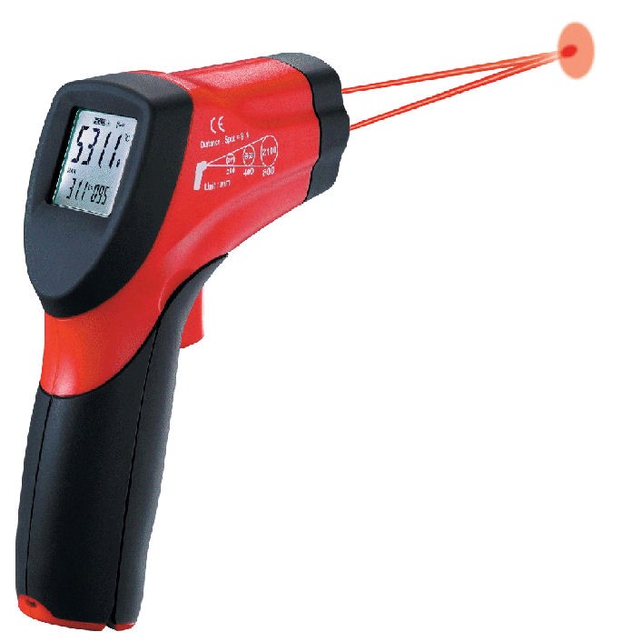
An infrared thermometer is a thermometer which infers temperature from a portion of the thermal radiation emitted by the object being measured. According to NCBI Journal, non-contact thermometers allow a person’s temperature to be taken with minimal (tympanic) or no (Non-contact infrared thermometer [NCIT], thermal scanner) contact with the person. The lack of contact also means the disinfection process between patients for the thermometers is minimal or unnecessary, allowing for easier and faster use when screening large numbers of people in settings like airports or border crossings.
In addition, Non-contact infrared thermometers are held three to 15 cm away from the patient and typically measure temperature on the forehead or temple. Which also reduces the possibility of infection for the person handling the device.
The intention is to make it as affordable and easy to build as possible, so that individuals, irrespective of the geographical location can build a functioning prototype, as well as learn more about the technology during the prototyping phase. This sensor could also include any of the following:
How it Works
Infrared light works like visible light--it can be focused, reflected or absorbed. Infrared thermometers usually use a lens to focus infrared light from one object onto a detector called a thermopile. The thermopile absorbs the infrared radiation and turns it into heat. The more infrared energy, the hotter the thermopile gets. This heat is turned into electricity. The electricity is sent to a detector, which uses it to determine the temperature of whatever the thermometer is pointed at. The more electricity, the hotter the object is ( Reference). To know more about how the IR Thermometer works, please visit Sensor Tips.
Incremental Innovation (Previous Developers)
Open source projects similar to this has already been done by guys that are almost close to Einstein. The links appended here are the projects that I find very similar to this project. Open Source Project1 and Open Source Project2 . With this projects, I could easily get some visual supports for the development part of this project.
What I designed
To contribute to the incremnetal project. I designed the electronic board for the FabOMeter, as well as the CAD design for the casing, the software program, and the holder of the component were developed freshly by me. Not saying that I am a genius, but I had a very good instructor. Below you can follow the thread of project which includes the list of components, CAD design, Electronic design and production, and other information.
List of Components
Most of the components for these projects were sourced from online platform such as Digikey, and some few ones from Conrad. This is with the exception of filaments used for the 3D printing and PlexiGlass, as well as MDF plywood for the laser cut frame, which we have in abundabce at our FabLab. However, you can find a detailed list of the components or tools that will be used for this project.
Note: There are other better sensors that could be used for this project. However, to afford them one might need to part ways with one of their kidneys.
You can download the bill of materials HERE, or go to the download section of this page.
CAD Design
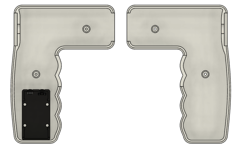
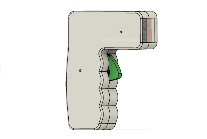
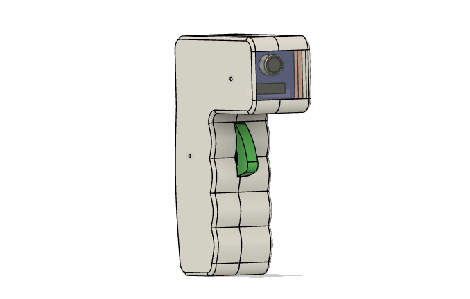
This is the first CAD design I came up with. However, I must say that it is subject to change, because this design only took cognizance of the temperature sensor. This might change depending on the addition of other components such as Infrared Thermal Camera module. In the case of this, I will definitely create another design that will accommodate the new component(s) added. In the meantime, just have fun with what I am able to do in the now.
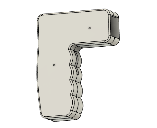
At this point, I can boldly say that my CAD Design, after steady participation in this rigorous yet enlightening Fab Academy, has gulped some steroids. If you do not believe me, please ask the old me. The illustration below represents the 2D sketch of the design.
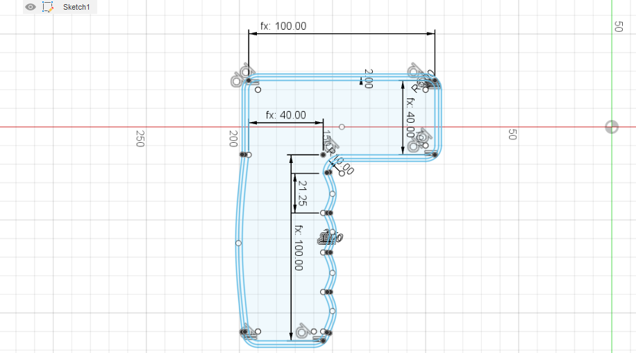
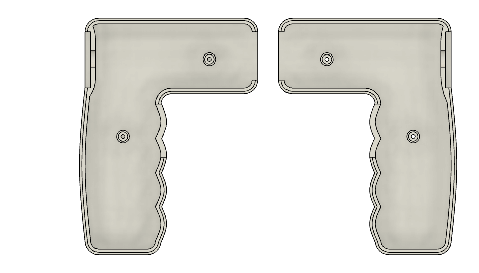
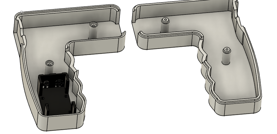
Once I was satisfied with the design, I proceeded into extruding it. This is represented below.
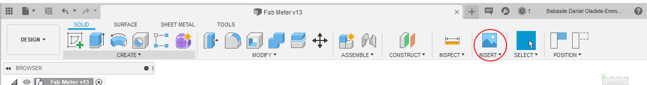
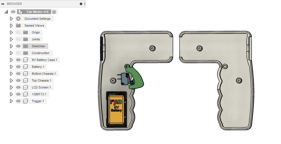
After this, I inserted a 9V battery connector from 'Insert' -> 'Insert Mc-Master Components'. However, I was unable to insert a 9V battery, so I created one to replicate the idea in mind. These are presented in the pictures below.
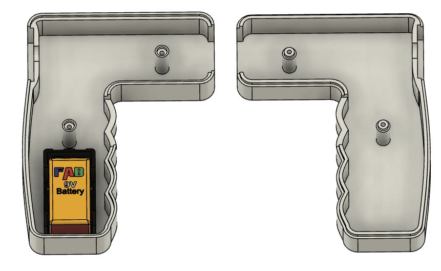
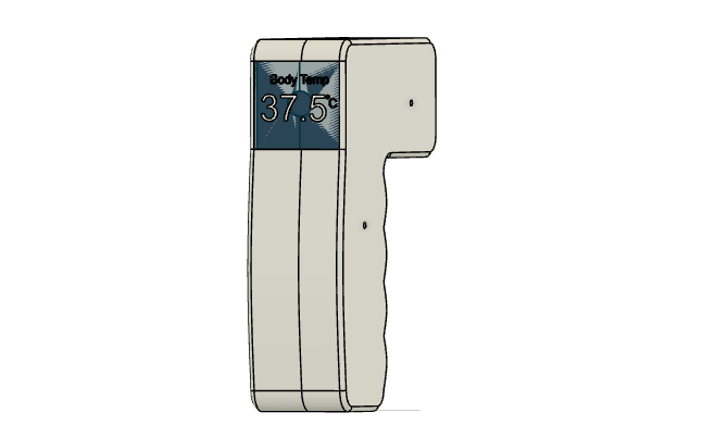
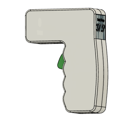
After this, I created an LCD display to express what I intended.
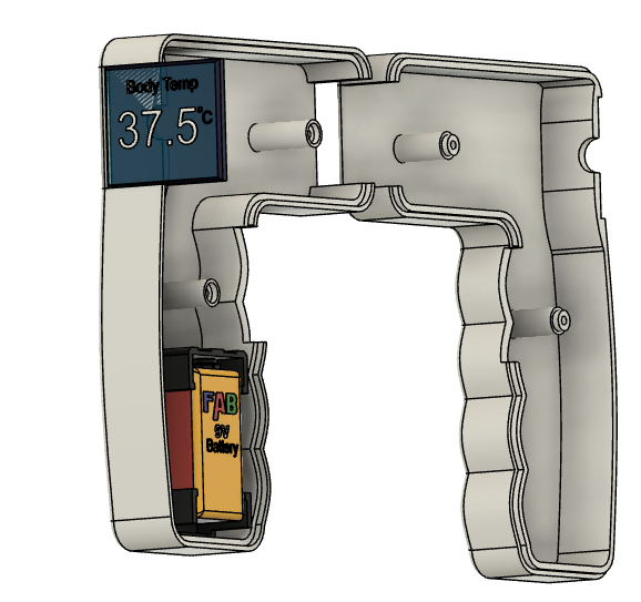
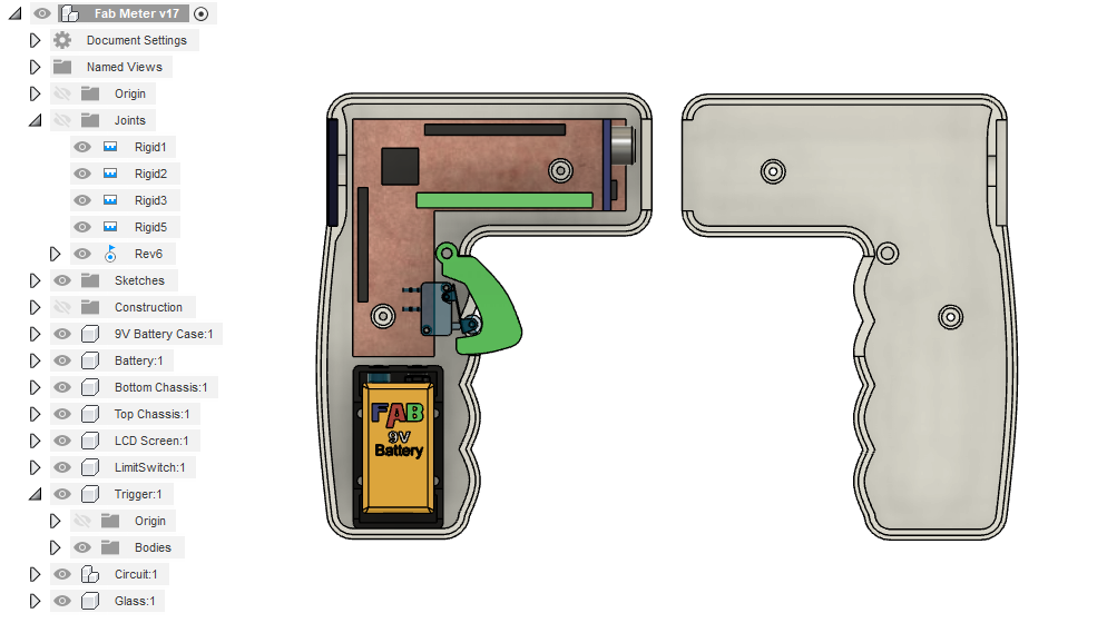
After the first phase, I created a demo of the circuit board, with the two sensors (IR temperature and Time of Flight), as well as the Raspberry Pi board. The pictures are displayed below.
In the event of any modifications, whose chances of occurring is highly probable, then the new modifications will be made in another heading depicting the modifications.
The next thing after this is to work on the electronic component of the device. I will be creating one with ATMEGA328 because I intend for it to be able to handle data analysis as well. The purpose of the data analysis is to be able to record the number of tests done in a day, the number of cases above the healthy threshold (I think 39oC), as well as the time the measurement was taken would also be noted. This would be useful in the case of tracking any individual that might slip through the test process.
Electronics Design
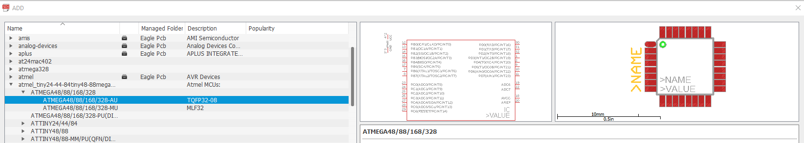
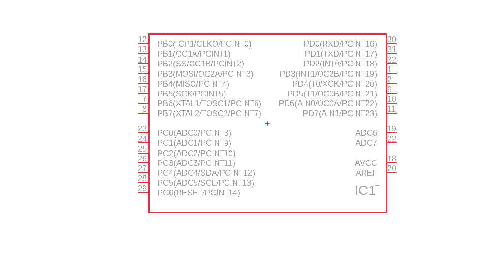
To design the unique circuit board for this device. As mentioned earlier, I will be making use of ATMEGA328. However, I could not find one in the library on the Eagle software. So what I did was to search on Google for the needed library. I found the ideal one on this Website. So after the download, I just installed it in the 'Library Manager' by following the following steps:
NOTE: After struggling to find the Eagle compatible library for ATMEGA328P-Au and MLX90614, and Raspberry Pi Zero online, I discovered another website that has most of the libraries. The Website is SnapEDA. This website has almost all libraries, datasheet, and most times the 3D Model for most of the components needed for the electronic design. However, you will have to create an account to access it.
NOTE: Please be warned that the this is the last time I will show how you can add a library on Eagle.
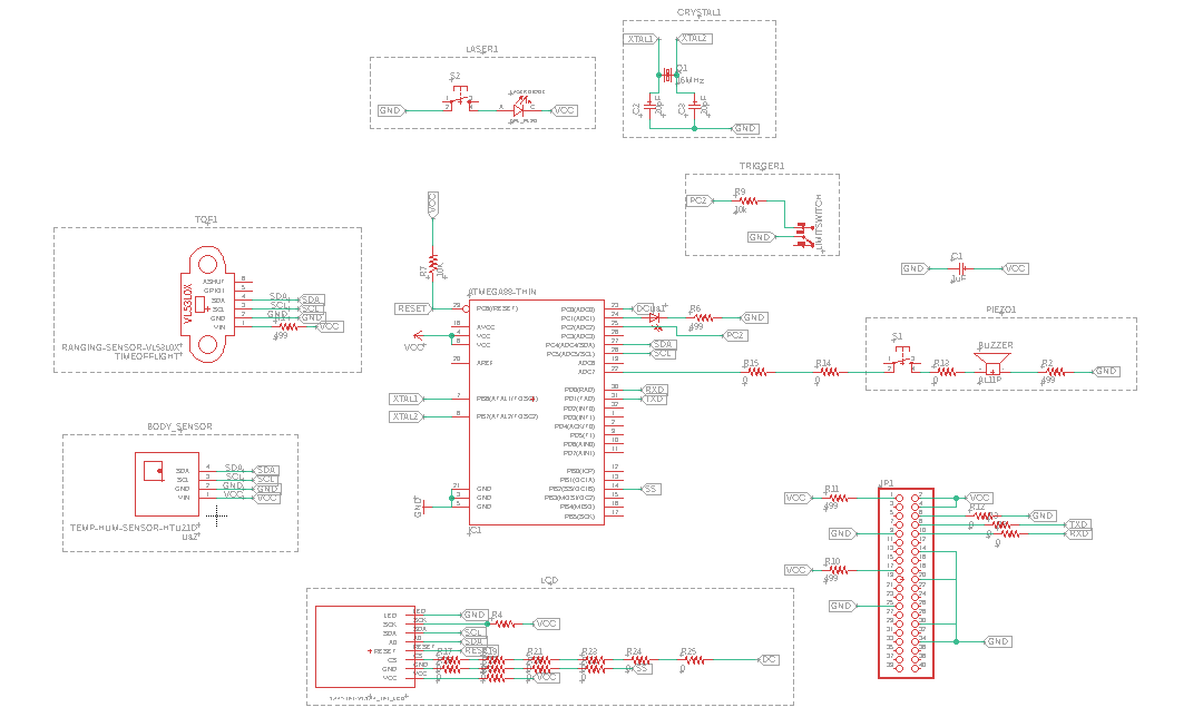
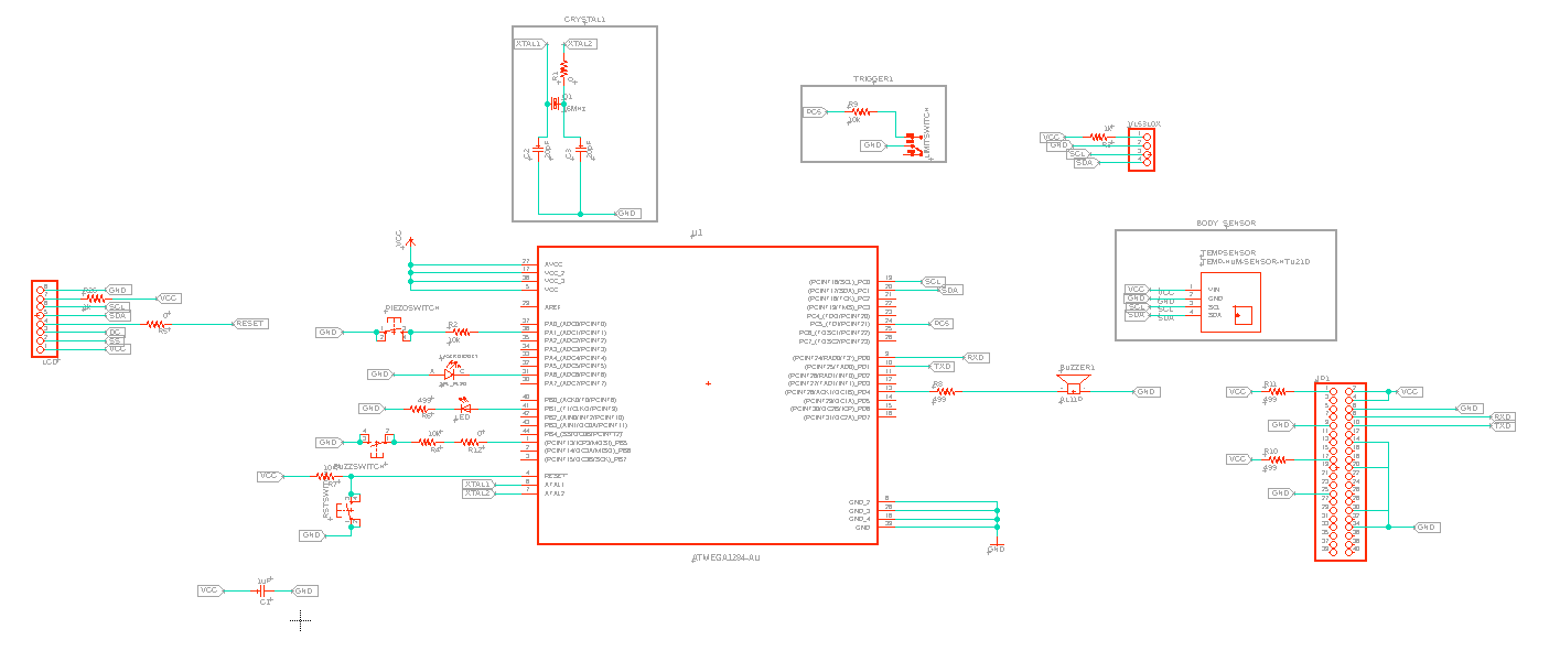
Now, we need to add other components to the electronic board. Below you will find the schematic of the electronic component of the device.
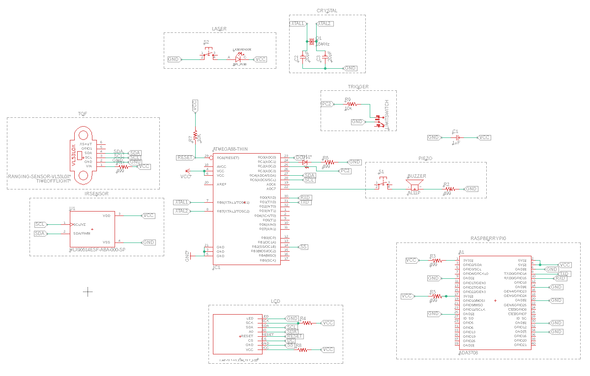
The next thing to worry about is the arrangment and connection of the components on the board. To be honest, I am not looking forward to this hassle. You can see for yourself, the bowl of unsavoured pasta that I am about to eat.
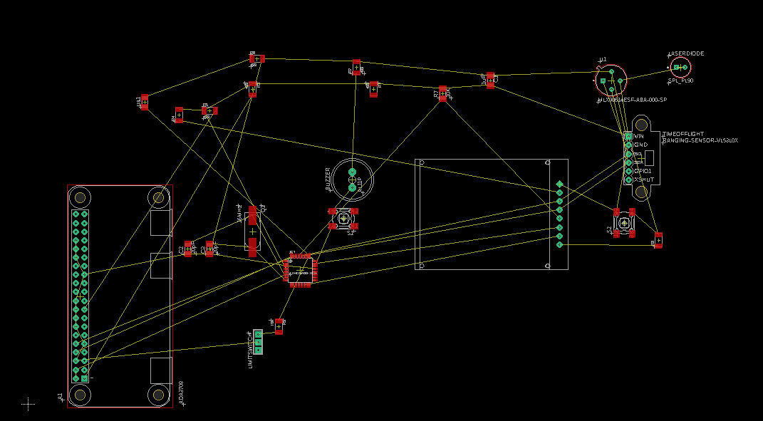
Another thing I intend to change is the physical arrangment of the components, especially with the Raspberry Pi Zero. I have been pondering how to connect it to the board, whether through a 40 pin header (2 x 20). However, the decision will be made as soon as I get the components to take accurate measures, and also to source for inspirations from my Innerman.
The picture above represents the option with the 40 pin header for the Raspberry Pi Zero. Hopefully, I will decide on the suitable approach to use soon.
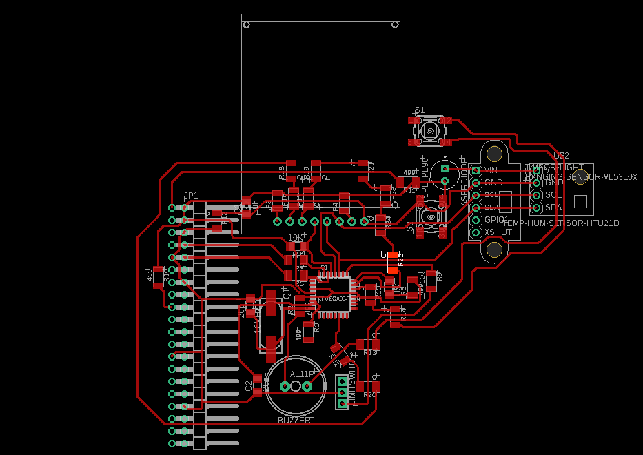
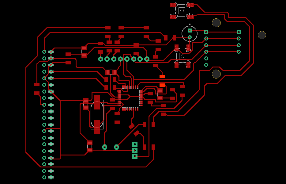
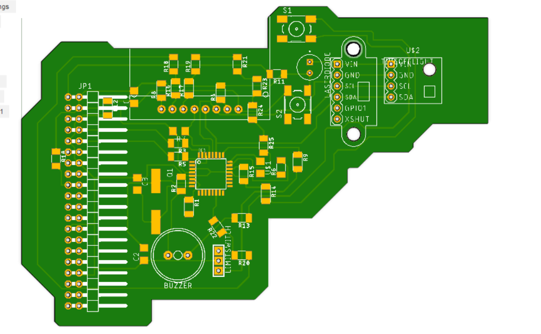
After working tirelessly for two days, I ended up designing the control board for FabOMeter. What can be observed from the illustrations that follows is the addition of lots of 'Zero Ohm' resistors to serve as a jumper wire in situations where making connections were impossible. Consult the pictures below.
After this minor modifications can be made based on how it fits into the CAD design of the chassis. This will be updated as the project progresses.
Migrate to Fusion 360
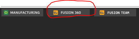
To migrate the electronic design to Fusion 360, all you have to do is to click on the toolbar titled 'Fusion 360' on the right hand side of the page. Please see the picture below.
After the migration, you just have to open Fusion. Then you will find the design already included in the CAD software. So you can now integrate it into the CAD design process for the development of a suitable prototype. Please see picture below.
Note This as well is subject to change.
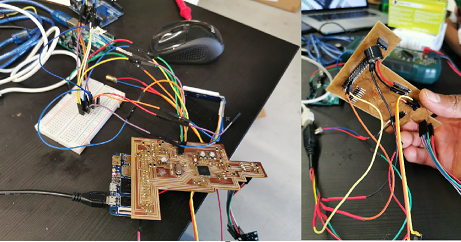
Components' Test
Since I have purchased and received 80% of the required components for the project. I decided to run a short test on the components before proceeding to the real fabrication and assembling. This will allow me to test the functionality of the components, as well as to learn how the electronic interface I am designing can better function to limit the possibilities of errors. Below, you will find the Arduino code used to test the components, as well as the video depicting the output of the test.
// Library for Time of Flight #include "Adafruit_VL53L0X.h" #include// Library for Temperature sensor #include // Library for TFT LCD Screen //#include #include #include #include int PushButton = 3; int LaserPin = 4; int Trigger = 5; int PushState = 0; int TriggerState = 0; TFT_ST7735 tft = TFT_ST7735(); // Invoke library, pins defined in User_Setup.h Adafruit_MLX90614 mlx = Adafruit_MLX90614(); Adafruit_VL53L0X lox = Adafruit_VL53L0X(); void setup() { // This is used to setup the LCD tft.init(); tft.setRotation(4); //You can rotate by changing from number 1 to 4 // put your setup code here, to run once: Serial.begin(9600); Serial.println("Adafruit MLX90614 test"); pinMode(PushButton, INPUT); pinMode(Trigger, INPUT); pinMode(LaserPin, OUTPUT); mlx.begin(); //Starts the Temperature sensor // wait until serial port opens for native USB devices if (!lox.begin()) { Serial.println(F("Failed to boot VL53L0X")); while (1); } delay(1); // power Serial.println(F("VL53L0X API Simple Ranging example\n\n")); } void loop() { // put your main code here, to run repeatedly: // Fill screen with black background colour tft.fillScreen(TFT_BLACK); // Set "cursor" at top left corner of display (0,0) and select font 2 tft.setCursor(0, 0, 2); TriggerState = digitalRead(Trigger); PushState = digitalRead(PushButton); //Serial.println(TriggerState); Serial.println(PushState); VL53L0X_RangingMeasurementData_t measure; Serial.print("Reading a measurement... "); lox.rangingTest(&measure, false); // pass in 'true' to get debug data printout! if (measure.RangeStatus != 4) { // phase failures have incorrect data Serial.print("Distance (mm): "); Serial.println(measure.RangeMilliMeter); tft.print("Distance (mm): "); tft.println(measure.RangeMilliMeter); } else { Serial.println(" out of range "); tft.println(" out of range "); } delay(100); if (TriggerState == HIGH && PushState == HIGH) { digitalWrite(LaserPin, HIGH); Serial.println("Initialize sensor!"); Serial.print("Room Temperature = "); Serial.print(mlx.readAmbientTempC()); Serial.print("*C\tObject = "); Serial.print(mlx.readObjectTempC()); Serial.println("*C"); Serial.print("Room Temperature = "); Serial.print(mlx.readAmbientTempF()); Serial.print("*F\tObject = "); Serial.print(mlx.readObjectTempF()); Serial.println("*F"); // Set the font colour to be white with a black background, set text size multiplier to 1 tft.setTextColor(TFT_WHITE, TFT_BLACK); tft.setTextSize(1); //This displays the welcome message in the colour of FabLab Red, Green, Blue tft.setTextColor(TFT_BLUE); tft.setTextFont(2); tft.print("FAB"); tft.setTextColor(TFT_GREEN); tft.setTextFont(2); tft.print("O"); tft.setTextColor(TFT_RED); tft.setTextFont(2); tft.println("METER"); // We can now plot text on screen using the "print" class tft.println("Sensor Active!"); tft.setTextColor(TFT_RED); tft.setTextFont(2); tft.print("Room(C) = "); tft.println(mlx.readAmbientTempC()); // Print room temperature in Celsius tft.print("Object(C) = "); tft.println(mlx.readObjectTempC()); // Print temperature of the object in Celsius tft.print("Room(F) = "); tft.println(mlx.readAmbientTempF()); // Print room temperature in Fahrenheit tft.print("Object(F) = "); tft.println(mlx.readObjectTempF()); // Print temperature of the object in Fahrenheit delay(5000); digitalWrite(LaserPin, LOW); //This turns of the laser diode after 5 seconds tft.setTextColor(TFT_RED); tft.setTextFont(4); tft.println("Push Trigger to start"); } if (TriggerState == HIGH && PushState == LOW) { digitalWrite(LaserPin, LOW); Serial.println("Diode is OFF!"); Serial.print("Room Temperature = "); Serial.print(mlx.readAmbientTempC()); Serial.print("*C\tObject = "); Serial.print(mlx.readObjectTempC()); Serial.println("*C"); Serial.print("Room Temperature = "); Serial.print(mlx.readAmbientTempF()); Serial.print("*F\tObject = "); Serial.print(mlx.readObjectTempF()); Serial.println("*F"); // Set the font colour to be white with a black background, set text size multiplier to 1 tft.setTextColor(TFT_WHITE, TFT_BLACK); tft.setTextSize(1); //This displays the welcome message in the colour of FabLab Red, Green, Blue tft.setTextColor(TFT_BLUE); tft.setTextFont(2); tft.print("FAB"); tft.setTextColor(TFT_GREEN); tft.setTextFont(2); tft.print("O"); tft.setTextColor(TFT_RED); tft.setTextFont(2); tft.println("METER"); // We can now plot text on screen using the "print" class tft.println("Diode Inactive!"); tft.setTextColor(TFT_RED); tft.setTextFont(2); tft.print("Room(C) = "); tft.println(mlx.readAmbientTempC()); // Print room temperature in Celsius tft.print("Object(C) = "); tft.println(mlx.readObjectTempC()); // Print temperature of the object in Celsius tft.print("Room(F) = "); tft.println(mlx.readAmbientTempF()); // Print room temperature in Fahrenheit tft.print("Object(F) = "); tft.println(mlx.readObjectTempF()); // Print temperature of the object in Fahrenheit delay(5000); digitalWrite(LaserPin, LOW); //This turns of the laser diode after 5 seconds tft.setTextColor(TFT_RED); tft.setTextFont(4); tft.println("Push Trigger to start"); } else if (TriggerState == LOW && PushState == HIGH) { digitalWrite(LaserPin, HIGH); Serial.println("Laser diode is working!"); tft.setTextColor(TFT_RED); tft.setTextFont(4); tft.println("Push Trigger to start"); delay(300); } else { digitalWrite(LaserPin, LOW); Serial.println("Push button to start!"); tft.setTextColor(TFT_RED); tft.setTextFont(4); tft.println("Push Trigger to start"); delay(300); } }
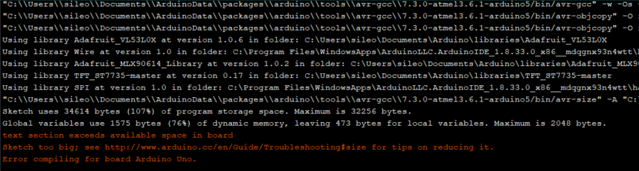
Upon the compilation of the code above, I got an error message showing that I have exceeded the available space on the board. After checking the link provided, I decided to comment out some libraries. The only scapegoat I found was the library of the 'Time of Flight' and all its associated codes. The error message is depicted in the picture below.
Solution to the insufficient Memory issue
After consulting the expertise of my Instructor, we figured two possibilities in solving this problem. One is to look for a library that uses the memory space minimally. The second option is to use a microcontroller (ATMEGA1284P) with a huge memory space instead of the initial ATMEGA328P. After considering the facts that I had to comment out the library for the Time of Flight (ToF) sensor, and the inevitable possibility that I might still be using more libraries, I decided to use the second option instead. The only thing is that the cost of the ATMEGA1284P is 5,81 Euro. This means a slight increase in the overall cost of the project. the data sheet of the ATMEGA1284P can be found Here.
Modifications
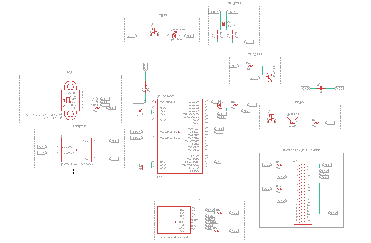
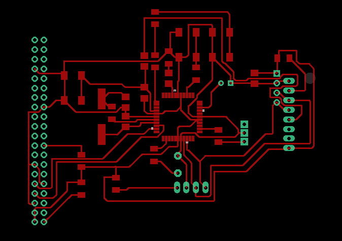
With regards, to change after encountering the error stated above, I changed the microcontroller to ATMEGA1284P. Below you will find the new schema and board layout for the new circuit board. Though ATMEGA1284P is more expensive than ATMEGA328P. However, it has sufficient memory space to handle the envisioned functionalities of the project.
Electronic Production
Milling
A lot has happened that I failed to document. This include wastage of money, due to the vibration of my big CNC breaking the end mills I bought with my hardearned money. I almost gave up, but I am too determined to lose out without a fight.
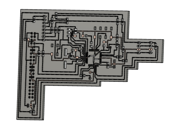
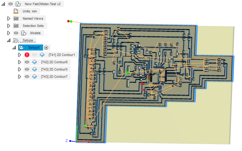
To do the milling, I used the adapted I used to mill the Electronic Production assignment. That is, I saved the PCB design as a DXF format. Then I inserted it into Fusion 360, then I extruded it to 2mm. Some pictures of the process will be depicted below.
Issue
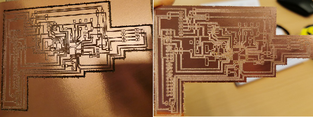
The first thing that happened during the milling process is that the V end mill I used first chirped away the layer of the PCB board. This can be seen in the picture below.
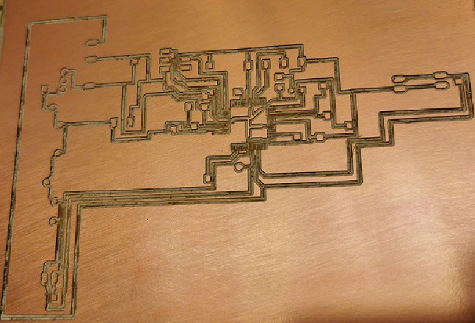
Then I made some modifications, and tried again. After two more attempts, I finally got a useful mill. However, not without a slight issue. The machine milled the center of the board before going back to it Home position.
Learning from experience, I stripped the surface of the board. After which I stuffed the board.
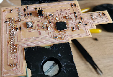
However, while trying to bootload the stuffed board to proceed to the programming of the board. I got the error message below
avrdude: Device signature = 0x000000
        avrdude: Yikes!  Invalid device signature.
         Double check connections and try again, or use -F to override
         this check.
This means there is a problem for the Arduino ISP to establish a communication channel with the board.
Well, I must accept my faults. I was the author of my own mishap. I made a mistake when soldering the chip on the board. I think I might have created a short circuit unknowningly.
So I decided to call it a day for now. Winners don't quit, and quitters don't win!
Fixed
So it appeared the error was partly due to some of my silly mistakes. With the amount of mistakes I have made on the Fab Academy journey, I should be given an award for the 'Most Mistake Maker on Earth.' What does not kill you makes you stronger. Below are some of the errors and how I fixed them:
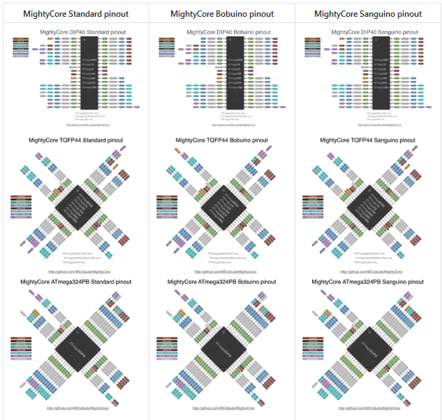
Below you will find a picture of the relative Pinout configuration I used. Please ensure to use the right pinout, becuase this tend to be different based on the library used to bootload the chip.
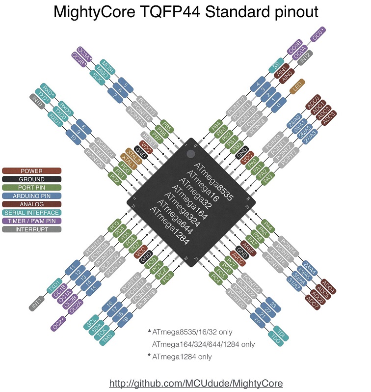
In my case, I used the standard pinout. So know the name of the configuration you used because that will determine the pinout configuration you must use when programming the chip. You can visit HERE for more useful information. In the meantime, you can use the image embedded below.
After successfully bootloading the chip, I ran a simple 'Blink' example to test whether the chip is functioning as expected. However, the port number must be the Arduino relative number which the LED of the board was connected to. In my case I connected the LED to PB1 which is port 41, and in Arduino, this is Port 1. The code is below.
// the setup function runs once when you press reset or power the board
        void setup() {
          // initialize digital pin LED_BUILTIN as an output.
          pinMode(1, OUTPUT);
        }

        // the loop function runs over and over again forever
        void loop() {
          digitalWrite(1, HIGH);   // turn the LED on (HIGH is the voltage level)
          delay(1000);                       // wait for a second
          digitalWrite(1, LOW);    // turn the LED off by making the voltage LOW
          delay(1000);                       // wait for a second
        }
Below, you will find the videoshowing the PCB board blinking.
New PCB Board Design
While programming the board, so many issues came up, especially with the TFT LCD screen I purchased for the project. This time around, it was not my fault. The manufacturers labeled the LCD as an I2C communication. Meanwhile, it actually uses SPI. Well, cheap stuffs has a funny way of equalizing the money saved with stress. So with the help of my instructor, we hacked the board so as to proceed with the test.
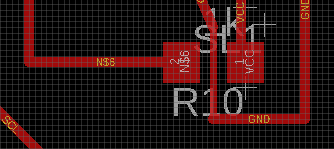
Another issue that arose, which also contributed to the redesigning of the PCB was that I used a resistor in order to reduce the voltage received by the LCD screen from 5V to 3.3V. I later learnt that a voltage regulator (3.3V) is the ideal option. Upon review, we also discovered that the voltage regulator would no longer be useful, since the Raspberry Pi Zero also supplies 3.3V. So I basically just removed the 1K Ohm resistor and connected the VCC of the LCD to the 3.3V slot of the Raspberry Pi Zero.
In addition, I confused the RES written on the LCD to Reset, which I prematurely connected to the RESET port of the chip. During the test, it became apparent that this shouldn't have been done in the first place. So I twisted my own ears and modified the design to solve the issues mentioned here.
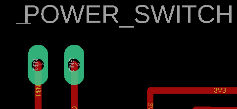
Lastly, I included a power switch so as to switch on and off the device.
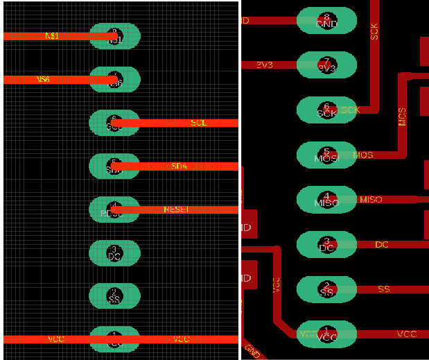
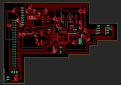
The picture below represent the new PCB design of the board.
New FabOMeter Case
Modification 1: After modifying and testing the components. I then finalized the CAD design for the housing of the device. Below, you can find the new case. So I can now proceed to 3D printing of the case.
Modification 2: After printing and testing the design modified above. I realized a lot could be improved on the CAD design. So I made some minor modifications to the design. This can be found here.
Modification 3: After presenting the project on the 29th of July 2020. I noticed the design could really be optimized. So optimizing it was exactly what I set my mind to achieve.
Snapping Button. So after this, I also made the vice to control the push button a snapping one. This design can also be found and also downloaded from the illustration below.
Coding
With the help of my instructor, I wrote the software program for the device in three phases. Phasial coding makes it easier to solve problems and get a good code.
Phase 1
I started by first attaching the sensors (MLX90614 Temperature sensor and the VL53L0X Time of Flight Sensor), and the limit switch to ensure that they are working properly.
        // Library for Time of Flight
        #include "Adafruit_VL53L0X.h"
        #include

          // Library for Temperature sensor
          #include

            boolean DiodeStatus;
            boolean BuzzerStatus;
            boolean LimitStatus;

            int LimitSwitch = 21;  //This assigns port 27 for the limit switch
            int LaserDiode = 28;  //This assigns port 17 for the laser diode
            int DiodeSwitch = 25; //This assigns port 20 for the laser diode's switch
            int BuzzSwitch = 24; //This assigns port 21 for the Buzzer switch
            int Buzzer = 12;  //This assigns port 30 for the piezo buzzer
            int LED = 1; //This assigns port 5 for the LED

            Adafruit_MLX90614 mlx = Adafruit_MLX90614();
            Adafruit_VL53L0X lox = Adafruit_VL53L0X();

            VL53L0X_RangingMeasurementData_t measure;

            void setup() {

              // put your setup code here, to run once:
              Serial.begin(9600);
              Serial.println("Adafruit MLX90614 test");

              pinMode(LimitSwitch,INPUT_PULLUP);
              pinMode(BuzzSwitch,INPUT);
              pinMode(DiodeSwitch,INPUT);
              pinMode(LaserDiode,OUTPUT);
              pinMode(Buzzer,OUTPUT);
              pinMode(LED,OUTPUT);

              BuzzerStatus = false;
              DiodeStatus = false;
              LimitStatus = false;

              mlx.begin(); //Starts the Temperature sensor

              // wait until serial port opens for native USB devices
              if (!lox.begin()) {
                Serial.println(F("Failed to boot VL53L0X"));
                while (1);
              }
              delay(1);

              // power
              Serial.println(F("VL53L0X API Simple Ranging example\n\n"));

            }

            void loop(){
              // put your main code here, to run repeatedly:

              LimitStatus = digitalRead(LimitSwitch);
              BuzzerStatus = digitalRead(BuzzSwitch);
              DiodeStatus = digitalRead(DiodeSwitch);

              Serial.println(LimitStatus);
              Serial.println("Test");

              while (LimitStatus == false) {

                //Control of the IR Sensor
                Serial.println("Initialize sensor!");
                Serial.print("Room Temperature = "); Serial.print(mlx.readAmbientTempC());
                Serial.print("*C\tObject = ");
                Serial.println(mlx.readObjectTempC()); //remove the ln infront of println
                Serial.println("*C");
                Serial.print("Room Temperature = "); Serial.print(mlx.readAmbientTempF());
                Serial.print("*F\tObject = "); Serial.print(mlx.readObjectTempF()); Serial.println("*F");

                //Control of the Time of Flight
                Serial.print("Reading a measurement... ");
                lox.rangingTest(&measure, false); // pass in 'true' to get debug data printout!

                if (measure.RangeStatus != 4) {  // phase failures have incorrect data
                  Serial.print("Distance (mm): "); Serial.println(measure.RangeMilliMeter);

                }

                else {
                  Serial.println(" out of range ");
                }

                LimitStatus = true;
              }

            }
Phase 2 (Arduino Programming)
Upon the successful implementation of the first phase, I proceeded to the second phase which is to attach and program the switches for the buzzer and Laser Diode. The code is appended below.
        // Library for Time of Flight
        #include "Adafruit_VL53L0X.h"
        #include

                // Library for Temperature sensor
                #include

                boolean DiodeStatus;
                boolean BuzzerStatus;
                boolean LimitStatus;

                int LimitSwitch = 21;  //This assigns port 27 for the limit switch
                int LaserDiode = A4;  //This assigns port 17 for the laser diode
                int DiodeSwitch = A0; //This assigns port 20 for the laser diode's switch
                int BuzzSwitch = A1; //This assigns port 21 for the Buzzer switch
                int Buzzer = 12;  //This assigns port 30 for the piezo buzzer
                int LED = 1; //This assigns port 5 for the LED

                Adafruit_MLX90614 mlx = Adafruit_MLX90614();
                Adafruit_VL53L0X lox = Adafruit_VL53L0X();

                VL53L0X_RangingMeasurementData_t measure;

                void setup() {

                  // put your setup code here, to run once:
                  Serial.begin(9600);
                  Serial.println("Adafruit MLX90614 test");

                  pinMode(LimitSwitch,INPUT_PULLUP);
                  pinMode(BuzzSwitch,INPUT_PULLUP);
                  pinMode(DiodeSwitch,INPUT_PULLUP);
                  pinMode(LaserDiode,OUTPUT);
                  pinMode(Buzzer,OUTPUT);
                  pinMode(LED,OUTPUT);

                  BuzzerStatus = false;
                  DiodeStatus = false;
                  LimitStatus = false;

                  mlx.begin(); //Starts the Temperature sensor

                  // wait until serial port opens for native USB devices
                  if (!lox.begin()) {
                    Serial.println(F("Failed to boot VL53L0X"));
                    while (1);
                  }
                    delay(1);

                  // power
                  Serial.println(F("VL53L0X API Simple Ranging example\n\n"));

                }

                void loop(){
                  // put your main code here, to run repeatedly:

                  LimitStatus = digitalRead(LimitSwitch);

                  //Turning the pushbutton to an On and off switch for the buzzer
                  if (digitalRead(BuzzSwitch) == LOW) {
                    Serial.println("Buzzer Working");
                    if (BuzzerStatus == true) {
                      BuzzerStatus = false;

                    }
                    else {
                      BuzzerStatus = true;
                    }
                    delay(500);
                    }

                    //Turning the pushbutton to an On and off switch for the Laser Diode
                   if (digitalRead(DiodeSwitch) == LOW) {
                    Serial.println("Diode Working");
                    if (DiodeStatus == true) {
                      DiodeStatus = false;
                    }
                    else {
                      DiodeStatus = true;
                    }
                    delay(500);
                    }


                  //Serial.println(LimitStatus);
                  Serial.println("Test");
                  Serial.println(BuzzerStatus);
                  Serial.println(DiodeStatus);

                  if (LimitStatus == true) {
                    digitalWrite(LaserDiode, LOW);
                  }

                  while (LimitStatus == false) {

                    //Control of the IR Sensor
                    Serial.println("Initialize sensor!");
                    Serial.print("Room Temperature = "); Serial.print(mlx.readAmbientTempC());
                    Serial.print("*C\tObject = ");
                    Serial.println(mlx.readObjectTempC()); //remove the ln infront of println
                    Serial.println("*C");
                    Serial.print("Room Temperature = "); Serial.print(mlx.readAmbientTempF());
                    Serial.print("*F\tObject = "); Serial.print(mlx.readObjectTempF()); Serial.println("*F");

                  //Control of the Time of Flight
                  Serial.print("Reading a measurement... ");
                  lox.rangingTest(&measure, false); // pass in 'true' to get debug data printout!

                  if (measure.RangeStatus != 4) {  // phase failures have incorrect data
                    Serial.print("Distance (mm): "); Serial.println(measure.RangeMilliMeter);
                  }

                  else {
                    Serial.println(" out of range ");
                  }

                  if (DiodeStatus == false) {

                    digitalWrite(LaserDiode, HIGH);
                  }
                  else {
                    digitalWrite(LaserDiode, LOW);
                  }

                  if (BuzzerStatus == false) {
                    tone(Buzzer, 1000,500);
                    delay(500);
                    noTone(Buzzer);
                  }
                  else {
                    //noTone(Buzzer);
                  }
                     LimitStatus = true;
                  }

                  }
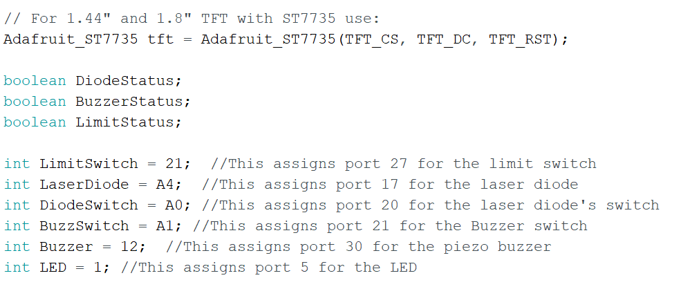
Phase 3 (Arduino Programming _ LCD)
This is the last phase of the Arduino programming part. Here, the LCD display would be programmed. Before I was using the standard ST7735 library to program the chip. However, this could not communicate successfully with ATMEGA1284P, so we switched to the good library from Adafruit . This now did the magic. It was even clearer than I had expected.
Do not forget to change the pins of the Adafruit setup to the Arduino compatible pins. Please see the picture below.
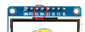
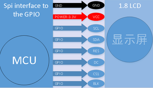
To connect the LCD, please follow the picture below, but do not forget that the I2C connection is an intentional error made by the manufacturer, probably to increase their sales. The ral connection is SPI not I2C. Also, the BLK should be connected to VCC.
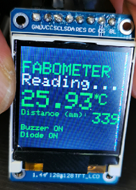
Working in phases has been really helpful. It is a divide and conquer strategy. Below you will find the code of the fully functional device, which also displays the status of the Buzzer and the Laser diode as soon as the device is switched on.
        /*
          Project Name: FABOMETER
          Developed By: Babasile Daniel Oladele-Emmanuel
          Instructor: Daniele Ingrassia
          Extra Support: Jorge Navarette Montalvo
          Extra Support: Ibrahim Barmacksiz

          This project was developed in completion of Fab Academy 2020. The idea came as a little response to the global pandemic (COVID-19).
          This code contains the fully functioning programme for the FabOMeter.
          FabOMeter is somewhat a smart Infrared Thermometer. It can measure the temperature and the distance between the object and the sensor for accurate reading.
          It is also enabled with a Buzzer and Raspberry Pi Zero to provide a data gathering funtionality for the device.
          */


          // Library for Time of Flight
          #include "Adafruit_VL53L0X.h"
          #include

          // Library for Temperature sensor
          #include

          #include     // Core graphics library
          #include  // Hardware-specific library for ST7735
          #include  // Hardware-specific library for ST7789
          #include

          #if defined(ARDUINO_FEATHER_ESP32) // Feather Huzzah32
            #define TFT_CS         14
            #define TFT_RST        15
            #define TFT_DC         32

          #elif defined(ESP8266)
            #define TFT_CS         4
            #define TFT_RST        16
            #define TFT_DC         5

          #else
            // For the breakout board, you can use any 2 or 3 pins.
            // These pins will also work for the 1.8" TFT shield.
            #define TFT_CS        A7 // Port 31 on the chip on ATMega1284 is assigned for CS
            #define TFT_RST        6 // I changed the Arduino RESET pin MISO on the chip
            #define TFT_DC        A6 // Port 30 on the chip is assigned for CS
          #endif

          // For 1.44" and 1.8" TFT with ST7735 use:
          Adafruit_ST7735 tft = Adafruit_ST7735(TFT_CS, TFT_DC, TFT_RST);

          boolean DiodeStatus;
          boolean BuzzerStatus;
          boolean LimitStatus;

          int LimitSwitch = 21;  //This assigns port 27 for the limit switch
          int LaserDiode = A4;  //This assigns port 17 for the laser diode
          int DiodeSwitch = A0; //This assigns port 20 for the laser diode's switch
          int BuzzSwitch = A1; //This assigns port 21 for the Buzzer switch
          int Buzzer = 12;  //This assigns port 30 for the piezo buzzer
          int LED = 1; //This assigns port 5 for the LED

          Adafruit_MLX90614 mlx = Adafruit_MLX90614();
          Adafruit_VL53L0X lox = Adafruit_VL53L0X();

          VL53L0X_RangingMeasurementData_t measure;

          void setup() {

           // This is used to setup the LCD

            //The Serial communication is not needed, but I left it here just in case one wants to troubleshoot using the serial port.
            Serial.begin(9600);
            Serial.println("Adafruit MLX90614 test");


            // Use this initializer if using a 1.8" TFT screen:
            tft.initR(INITR_BLACKTAB);      // Init ST7735S chip, black tab

            // put your setup code here, to run once:

            pinMode(LimitSwitch,INPUT_PULLUP);
            pinMode(BuzzSwitch,INPUT_PULLUP);
            pinMode(DiodeSwitch,INPUT_PULLUP);
            pinMode(LaserDiode,OUTPUT);
            pinMode(Buzzer,OUTPUT);
            pinMode(LED,OUTPUT);

            BuzzerStatus = false;
            DiodeStatus = false;
            LimitStatus = false;

            mlx.begin(); //Starts the Temperature sensor

            // wait until serial port opens for native USB devices
            if (!lox.begin()) {
              Serial.println(F("Failed to boot VL53L0X"));
              while (1);
            }
              delay(1);

            // power
            Serial.println(F("VL53L0X API Simple Ranging example\n\n"));

          }

          void loop(){
            // put your main code here, to run repeatedly:


            LimitStatus = digitalRead(LimitSwitch);

            //Turning the pushbutton to an On and off switch for the buzzer
            if (digitalRead(BuzzSwitch) == LOW) {
              Serial.println("Buzzer Working");
              if (BuzzerStatus == true) {
                BuzzerStatus = false;
              }
              else {
                BuzzerStatus = true;
              }
              delay(500);
              }

              if (BuzzerStatus == false) {
                //Displays the status of the Buzzer
              tft.setCursor(5, 100);
              tft.setTextSize(1);
              tft.setTextColor(ST77XX_GREEN);
              tft.println("Buzzer ON");
              }else {
                //Displays the status of the Buzzer
                tft.setCursor(5, 100);
                tft.setTextSize(1);
                tft.setTextColor(ST77XX_BLUE);
                tft.println("Buzzer OFF");
              }

              //Turning the pushbutton to an On and off switch for the Laser Diode
             if (digitalRead(DiodeSwitch) == LOW) {
              Serial.println("Diode Working");

              //Displays the status of the Diode
              tft.setCursor(5, 110);
              tft.setTextSize(1);
              tft.setTextColor(ST77XX_GREEN);
              tft.println("Diode ON");
              if (DiodeStatus == true) {
                DiodeStatus = false;
              }
              else {
                DiodeStatus = true;
              }
              delay(500);
              }
              if (DiodeStatus == false) {
                //Displays the status of the Diode
              tft.setCursor(5, 110);
              tft.setTextSize(1);
              tft.setTextColor(ST77XX_GREEN);
              tft.println("Diode ON");
              } else {
                //Displays the status of the Diode
              tft.setCursor(5, 110);
              tft.setTextSize(1);
              tft.setTextColor(ST77XX_BLUE);
              tft.println("Diode OFF");
              }

            //The Serial communication is not needed, but I left it here just in case one wants to troubleshoot using the serial port.
            Serial.println("Test");
            Serial.println(BuzzerStatus);
            Serial.println(DiodeStatus);

            if (LimitStatus == true) {
              digitalWrite(LaserDiode, LOW);
            }

            while (LimitStatus == false) {

              //Control of the IR Sensor
              Serial.println("Initialize sensor!");
              Serial.print("Room Temperature = "); Serial.print(mlx.readAmbientTempC());
              Serial.print("*C\tObject = ");
              Serial.println(mlx.readObjectTempC()); //remove the ln infront of println
              Serial.println("*C");
              Serial.print("Room Temperature = "); Serial.print(mlx.readAmbientTempF());
              Serial.print("*F\tObject = "); Serial.print(mlx.readObjectTempF()); Serial.println("*F");

              tft.setTextWrap(false);
              tft.fillScreen(ST77XX_BLACK);
              tft.setCursor(5, 20);
              tft.setTextColor(ST77XX_GREEN);
              tft.setTextSize(2);
              tft.println("FABOMETER");
              tft.setCursor(5, 35);
              tft.setTextColor(ST77XX_WHITE);
              tft.setTextSize(2);
              tft.println("Reading...");
              tft.setCursor(5, 55);

              //This piece of code changes the color of the text on the display based on the temperature. The reason is to flag the person taking the measurement in case the person being measured has high fever.
              if (mlx.readObjectTempC() < 38) {
                tft.setTextColor(ST77XX_GREEN);
                tft.setTextSize(3);
                tft.print(mlx.readObjectTempC());
                tft.setTextSize(1);
                tft.print("*");
                tft.setTextSize(2);
                tft.println("C");
              }
              else {
                tft.setTextColor(ST77XX_BLUE);
                tft.setTextSize(3);
                tft.print(mlx.readObjectTempC());
                tft.setTextSize(1);
                tft.print("*");
                tft.setTextSize(2);
                tft.println("C");
              }
            //tft.print(mlx.readObjectTempF()); tft.println("*F");

            //Control of the Time of Flight
            Serial.print("Reading a measurement... ");
            lox.rangingTest(&measure, false); // pass in 'true' to get debug data printout!

            if (measure.RangeStatus != 4) {  // phase failures have incorrect data
              Serial.print("Distance (mm): "); Serial.println(measure.RangeMilliMeter);
              tft.setTextColor(ST77XX_GREEN);
              tft.setCursor(5, 80);
              tft.setTextSize(1); tft.print("Distance (mm): ");
              tft.setTextSize(2); tft.println(measure.RangeMilliMeter);
            }
            else {
              Serial.println(" out of range ");
              tft.setTextSize(2);
              tft.println(" out of range ");
            }

            if (DiodeStatus == false) {
              digitalWrite(LaserDiode, HIGH);
            }
            else {
              digitalWrite(LaserDiode, LOW);
            }

            if (BuzzerStatus == false) {
              tone(Buzzer, 1000,500);
              delay(500);
              noTone(Buzzer);
            }
            else {
               /* */
              }
               LimitStatus = true;
            }

          }
Now that the Arduino program has been fully developed. I will proceed to working on the interface of the Raspberry Pi Zero. This will enable the data gathering analysis. However, I have not decided on the type of data to collect. I think knowing the location where the measurement was taken and the time it was taken would be highly useful for tracking and tracing purposes.
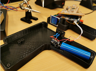
Phase 4 (Data Gathering)
The code and platform for the Raspberry Pi will be uploaded below.
I bought a Banana Pi Zero for this project. However, their documentation is so poorly done. After cracking and grinding for a long time. I finally got the Armbian OS installed on the Banana Pi. The Armbian OS can be downloaded from this link LINK.
For want of time, I decided to suspend the data analytics part of the project till I can get a Raspberry Pi or make a data analytics component myself.
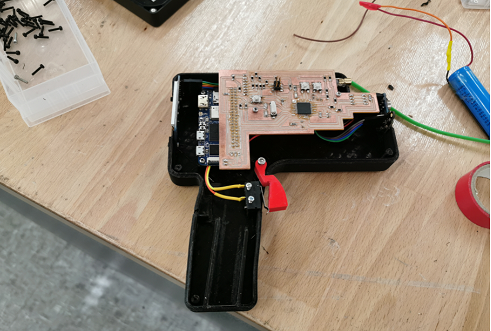
Assembly
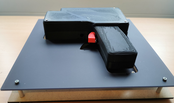
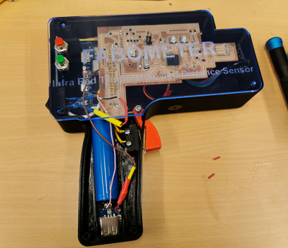
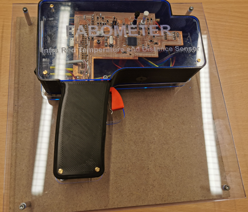
After the successful implementation of phase 1 to 3, I proceeded to assembling the electronics in the case. To get up to this point, I made series of modifications which are depicted in the CAd drawings represented above. So the final design (at least for now) has a transparent cover which shows the content of the device. Therefore, this phase represents the assembly process of the device. This will be depicted using various pictures as well as little explanation here and there.
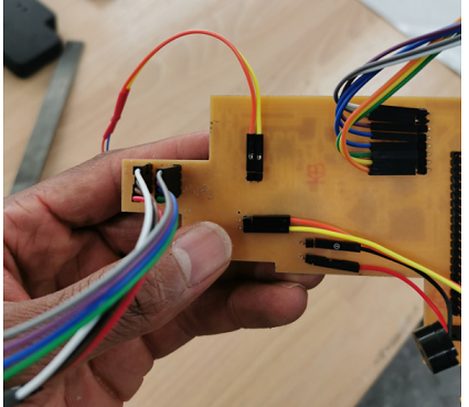
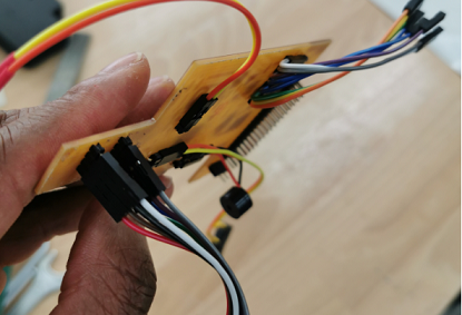
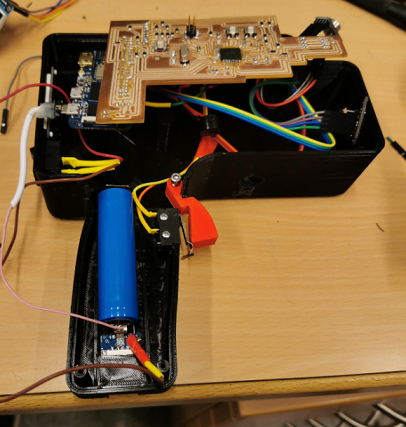
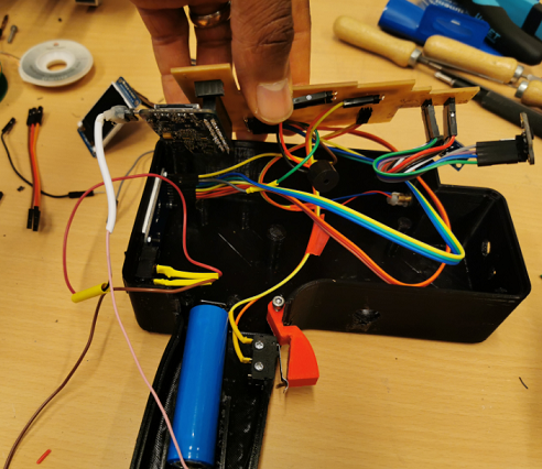
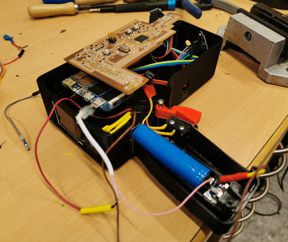
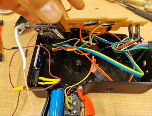
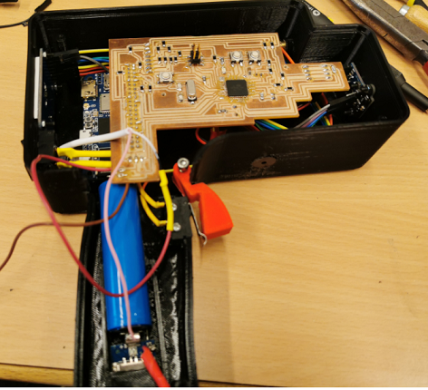
So the first thing I did was to connect the electronics components to the electronic board. This can be found in the pictures below.
After corresponding this to the electronics, then I proceeded with the assembly of the electronics in the housing case.
Case - First Attempt
A lot happened in the process, which I would like to document in this phase. First, I tried out the first design of the CAd, but it was a little better than useless.
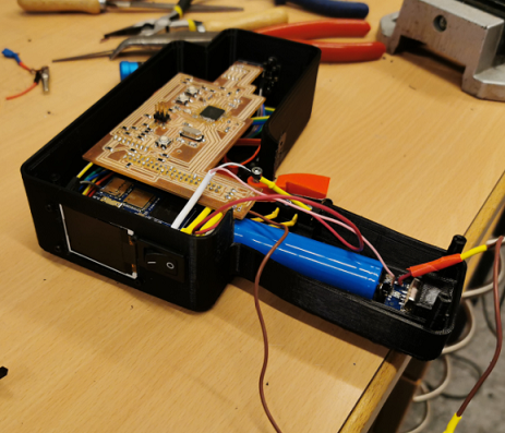
Case - Second Attempt
So after this, I decided to use my brain more effectively. So I went back to work and modified the design then I made a sizable progress. At least it was useful enough for me to present the project on the day apportioned for me to do that.
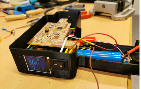
In case you are wondering the problem with this assembling, let me come clean how show you the silly mistake I made. As can be seen in the picture below, I did not think about how to screw or attach the uüpper part of the LCD to the case. This made the job looked less than something from Wakanda. Coupled with some other silly miscalculations on the switch and other areas.
So I decided to leave it till I am done defending my PhD thesis. I also had to finish my John Maxwell Leadership certification program. Father 'Time' was really not on my side. Below you will find a pictorial depiction of what my final project looked like as at July 27, 2020.
That does not look bad for a silly mistake maker like me. Well, one thing my time at FabLab has taught me is that, 'Mistakes are very much welcome in FabLabs', and one should not be afraid of making mistakes. On the contrary, mistakes should be celebrated, as long as one learns vital lessons from it.
The video shows the functional test made during this attempt.
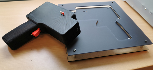
Case - Third Attempt
So upon the successful defense of my thesis, Which means I can now be called Dr. Babasile Daniel or a Life Coach!, I decided to go back to work before acute laziness gets the best of me. I heeded the advise of my instructor t make the top out of a transparent component to show the interior of the device.
Case - Laser Cut
So, like a good student of an impeccable instructor, I cut the transparent cover using a 3mm plexi glass. For information on the settings used for the laser cutting part of this job, please consult the assignment done on Week 3.
So I made a 2D design on Corel Draw. Which I then proceeded to the laser cutter to cut it.
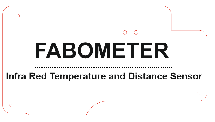
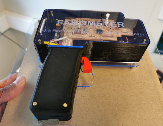
As can be seen from the picture below, I also made a holding fram for the device, which I also cut out at the same time I was cutting the transparent cover for the device.
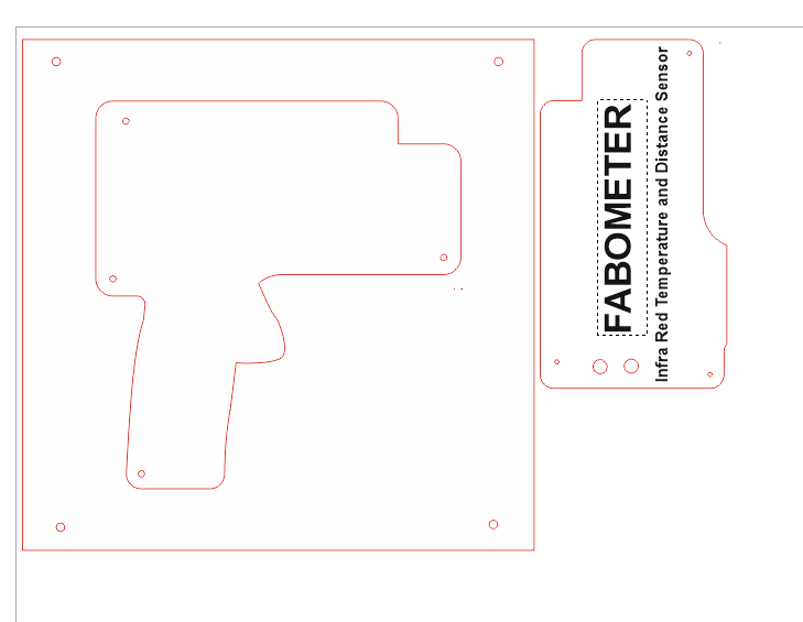
Below is what the picture of the laser cut job looks like.
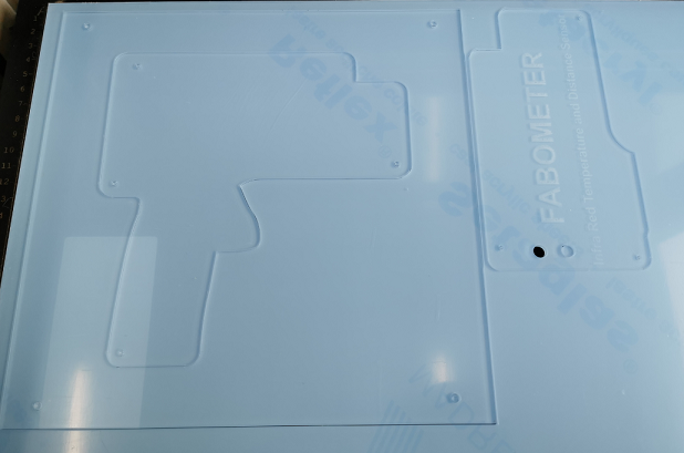
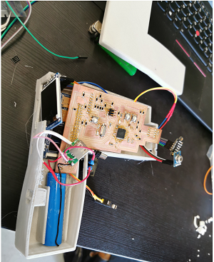
Upon the satisfaction with the cleanliness of the design, I proceeded with the assembling of the components in the modified design.
During this modification phase, I also thought of using a new tactile switch as shown in the picture below.
However, I concluded against such venture since I only have one electronic board. So in the future, I will definitely give that a try. But for now, we continue with the assembly of the device.
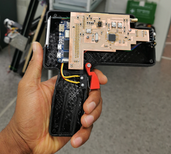
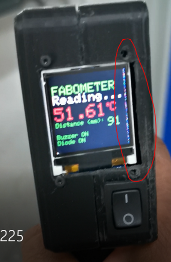
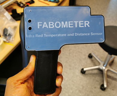
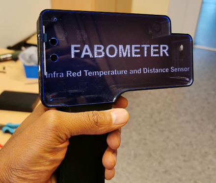
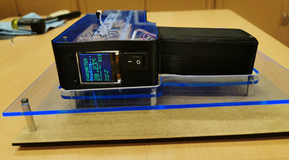
After all these gymnastics, I checked to see if the components are still functioning as intended. I basically switched the device ON.
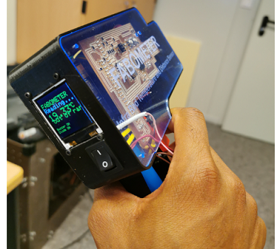
I know it looked like some James Bond 007 stuff. But I was averagely satisfied with my progress. Which means there is always room for improvement.
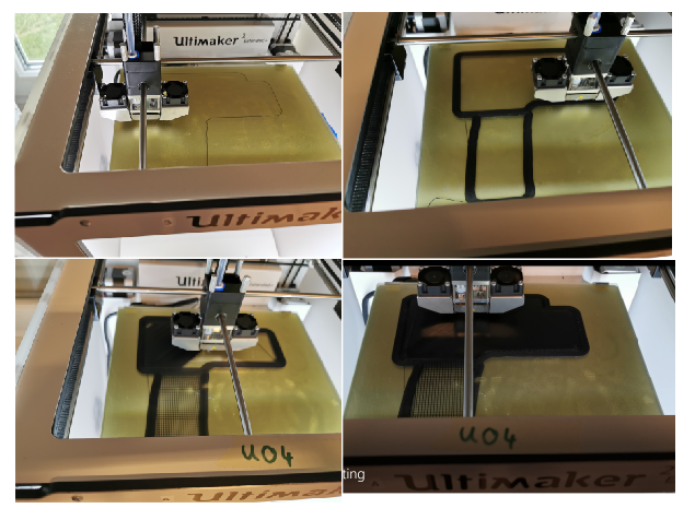
Case - 3D Printing
To print the case of the device, I used Ultimaker Extended 2+, using the settings used in Week 5. Please consult the appended link to see the settings. Below you can find the picture of the printing.
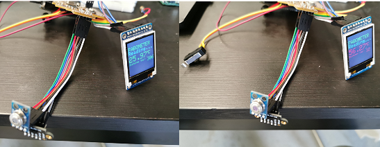
Upon my satisfaction, then I proceeded with making a functional test to ascertain that the device works after enclosing everything. So I did series of test using different temperatures. This will be depicted with the videos embedded below.
Quality Test
Below is the video of the first functional test done on the new assembled device.
Then I made a test to read my body temperature. Well, it is COVID19 season, so you cannot be too sure.
When I noticed my body temperature was ideal. I now made extra test with the device. This is depicted in the video below.
Presentation Video and Slide
You can find the picture of the presentation presented on the 29th of July HERE.

The video presented on this day can be seen HERE
Future Modification
Since I know without pretence that I could have done better with the project, I list here areas through which the project can be improved.
Final Words - Lessons Learnt
The major lesson I learnt from the painful and lovely Fab Academy journey is that Everything is possible to those who are willing to bravely pursue their growth plan.
My Fab Academy Journey was loaded with so many challenges. First with COVID19, then with malfunctioning machineries such as the giant CNC machine at my lab, wastage of money, and personal investment of my personal funds in solving incumbent issues. However, instead of these issues making a chicken soup out of me, it only refined my determination to accomplish my goals of being a certified FabLab Manager.
Was it easy or conducive? Of course, NOT.
Would I do it again if I get the opportunity to subject myself to another similar painful journey? Well, not that I am a sadist, but the pain really made me discover something new about myself. So, YES, I will definitely do it again if I got an opportunity to make myself better.
Would I recommend Fab Academy to others? Well, it depends on the risk loving or risk taking nature of the individual. However, I will implore others to do Fab Academy if they need it for their future. Without doubt, Fab Academy will help to create an ideal World.
Not that anything in life is guaranteed. But the only way to get a guarantee is to DO what you never knew or thought you could do. So LIFE here I come to lay claim to my Kingdom.
You can download the Schematic of the electronic board HERE, or go to the download section of this page.

This work is licensed under a Creative Commons Attribution-ShareAlike 4.0 International License.