'He who wears tomorrow's clothes today should be ready to walk naked tomorrow.'
African Proverbs
Concept: CAD Software Description
FreeCAD
In this link , I presented a tabulated summary of some of the CAD softwares available out there. Please slide over there to know more, because here, I will be delving into the real deal, which is how to design using two of the numerous CAD software. I believe a suttle disclaimer is needed right here, 'This is not for the faint-hearted'. The fact that you are still here shows you are braver than Sir William Wallace of the Braveheart.
So if you are ready, then I am ready! Vamonos señor y señora!
To show you how free and enjoyable FreeCAD is *Exageratting*, I will attempt to show a step by step journey from 2D to 3D by 'attempting' to create a 3D design of the FabLab Logo. Please DO NOT ignore the quote placed on attempting. So do not crucify me if it doesn't look like what you expected. Beauty is in the eye of the beerholder!

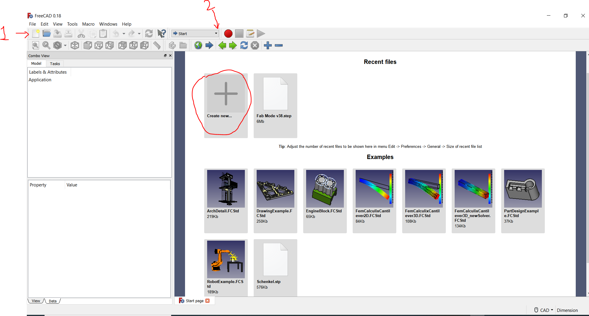
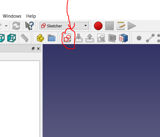
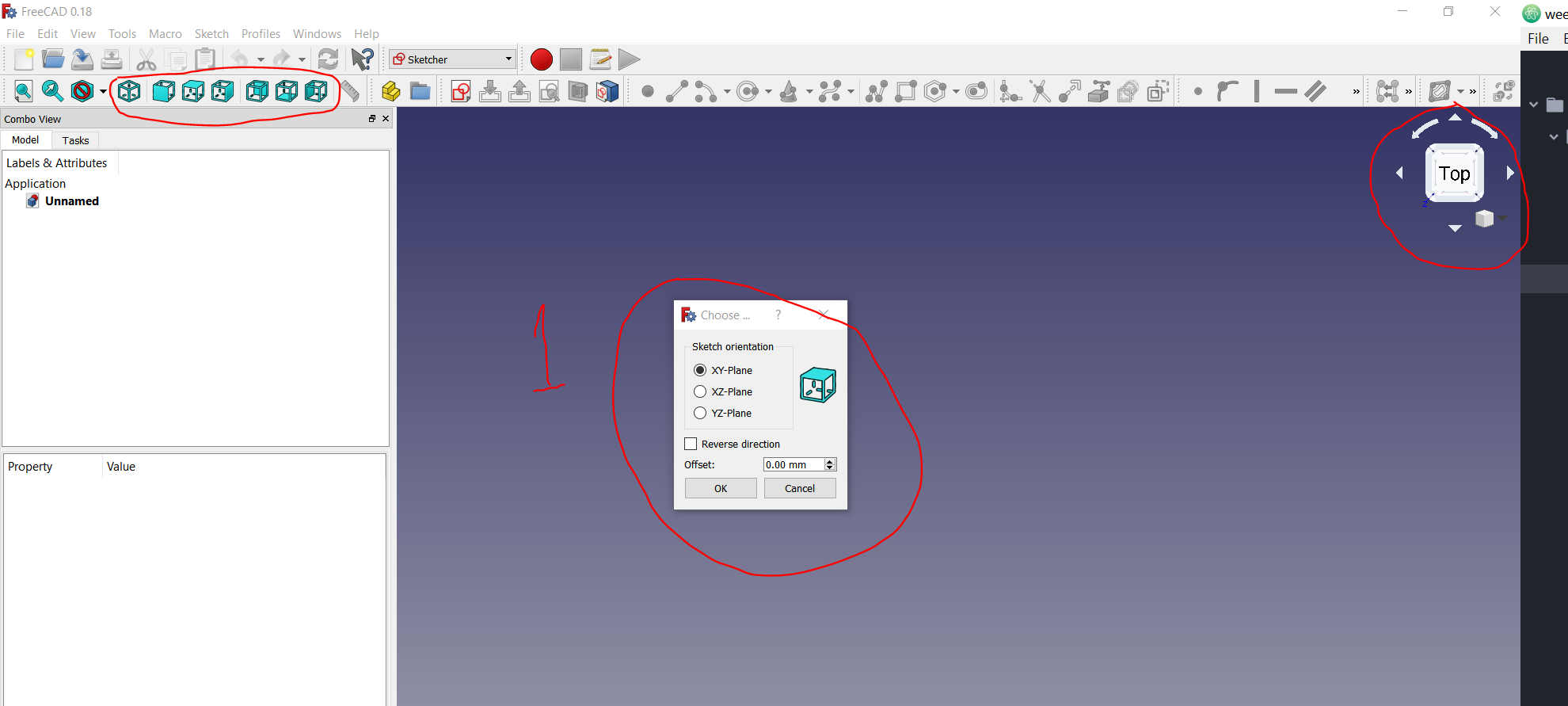
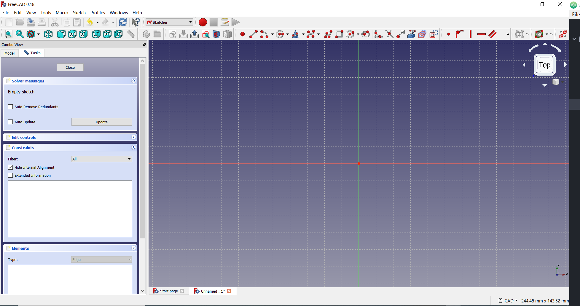
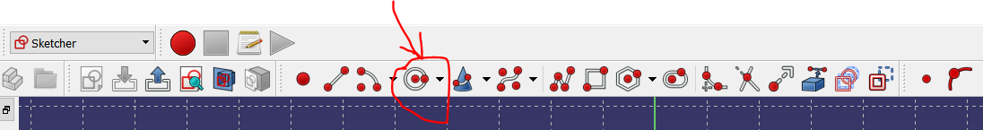
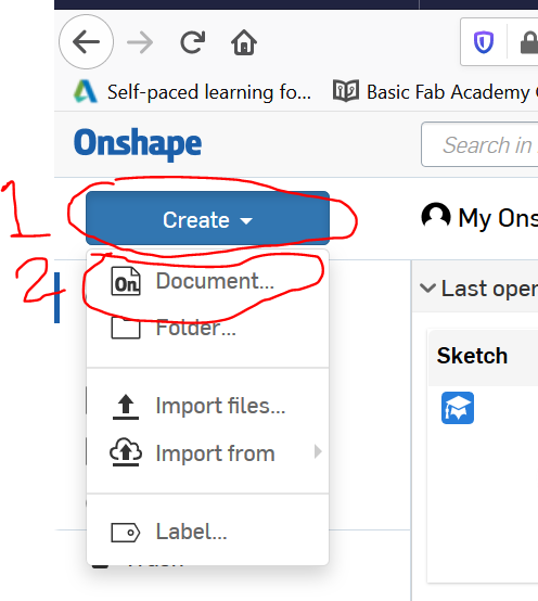
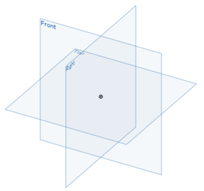
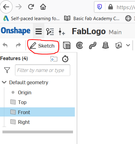
Start FreeCAD by clicking the shortcut on your desktop. Once the software is open, then click the 'New Document' icon on the Menu Tab (this is referred to as 1 in the diagram below - the plain document icon with the rising sun). There are two other means to select New Document, you could select it from the 'File' dropdown menu or the 'Create new document' option circled in the picture below. Once clicked, then click the dropdown menu labeled 2 in the diagram below. Once step 2 has been clicked , then you can select 'Sketches' from the list which also contains 'Part', 'Part Design', 'OpenSCAD', and many more. To begin with the 2D designing, I clicked on the 'Create new sketch' (circled in the second picture below). This takes you into an empty page which requests you to choose the sketch orientation as depicted in the third picture below. Just select the orientation more suitable for you. I mostly use the XY-Plane, so you could just stick to this default option. You could also change the orientation by using the other circled options. This will take you to the view depicted in the fourth picture.
The real creativity now comes into action. Don't forget that my plan is to draw the FabLab logo. Just like the African proverb that says 'A market has more than one entry point', there are several ways with which this could be done. So I am simply using the one I found suitable for me.
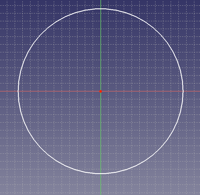
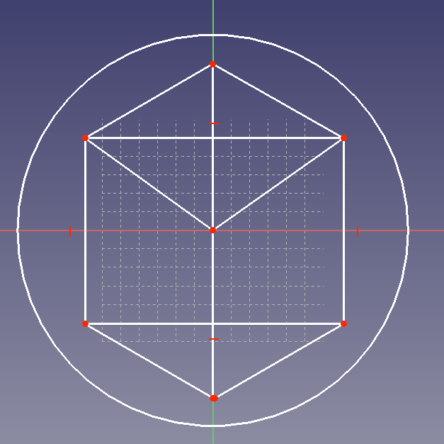
I first drew a circle of 100mm by clicking the circle icon on the Menu tab (see picture below). In case you want to resize the circle, just click and hold down on any point in the circle, then drag up to increase or drag down to reduce the circle. So I now drew a cube inside the circle to make it easy for me to at least get the symmetry of the FabLab logo. after which I trimmed out the excess lines I deemed surplus to requirements.
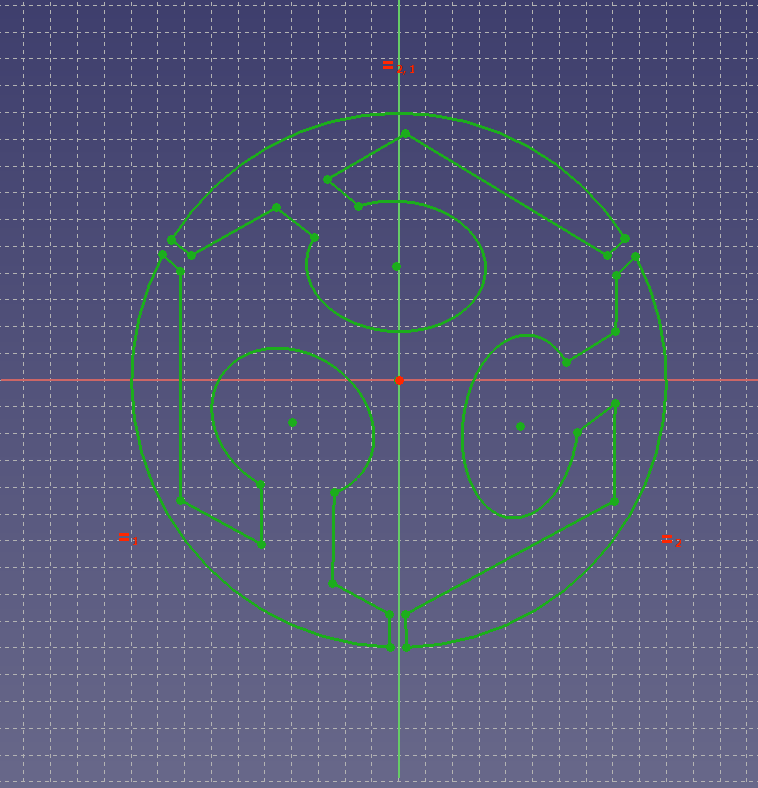
This is a bit irrelevant, but the old nemesis I had with FreeCAD came back to hunt me. As you can see below, I felt I had finished sketching the logo. However, FreeCAD had other plans. I never get a hang of the constraints. This is the real reason why I find it unusable and extremely not user-friendly. At least from my perspective. If you know how to read emotions, you would notice I was a bit frustrated with the program. But I plan to give it a go one more time.
Onshape
After unsuccessfully battling with FreeCAD, I decided to use Onshape instead. Some would think I have gained lots of weight that is why I decided to be Onshape. Anyways, we are all master of our thoughts. So I will explain how I successfully moved from 2D to 3D in Onshape.
You can check the table on this link to get a summary of Onshape. I found Onshape very similar to Fusion 360, in that, both are based on cloud, which means you do not need to stress your system out by saving the designs on your local hard drive. This also gives you the opportunity to work remotely in any geographical location as long as there is an Internet service. However, unlike Fusion 360, you do not need to download and install any software package on your system. Onshape is totally Internet-based.
To use Onshape, you just have to do the following:
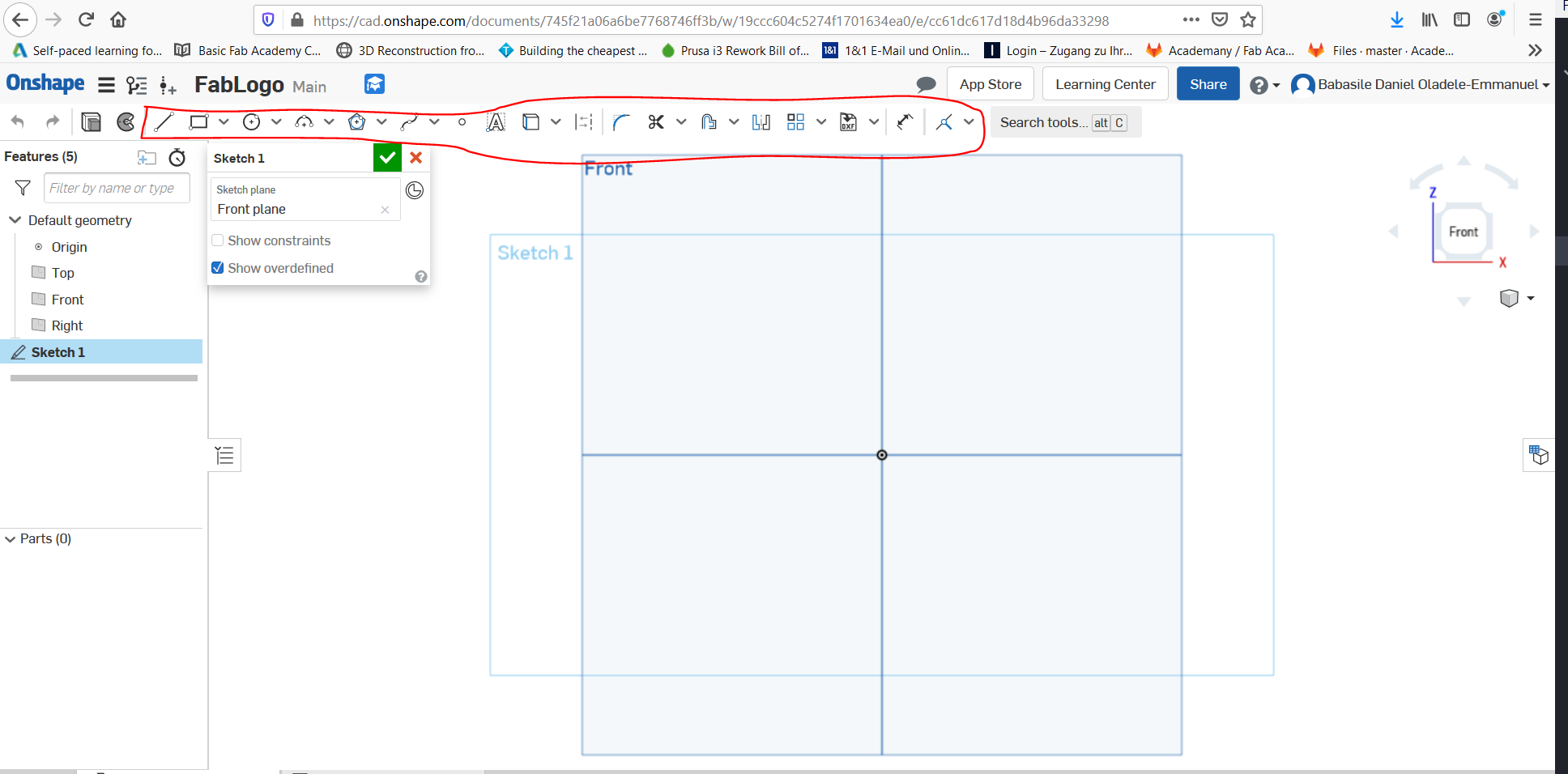
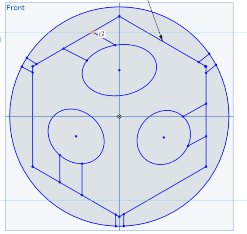
Now that our design project is well under way, what I did was to select the 'Polygon' shape on the sketch menu. Why did I choose the polygon? Because I noticed the FabLab logo was created using a Hexagon. To those who have forgotten what an hexagon is, a Hexagon is a Six-sided shape. You can clap for me if you want!
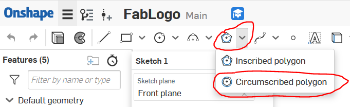
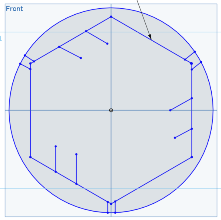
Then I created the hexagon right in the centre of the workspace. After which I used the 'Offset' option to create another external circle, Then I trimmed the inner circle.
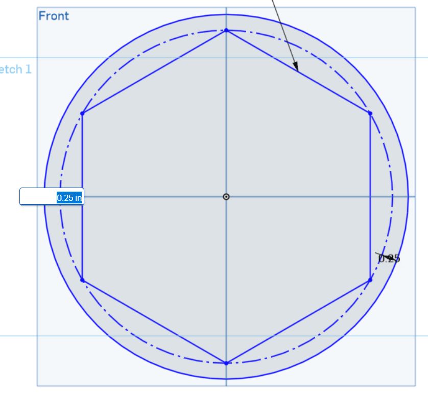
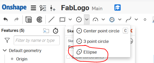
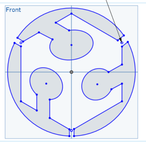
After this I just inserted lines and ellipes to trace out the shape of the logo (See figures below).
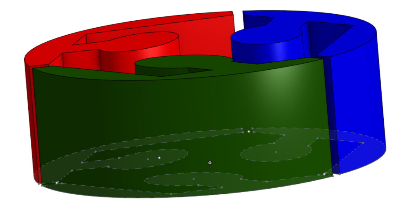
After this, all I did was to trim out the unwanted lines. Then I extruded (Shift + e) the shapes.
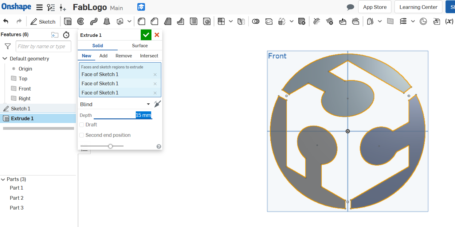
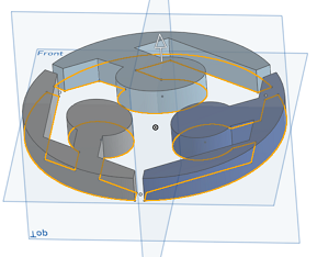
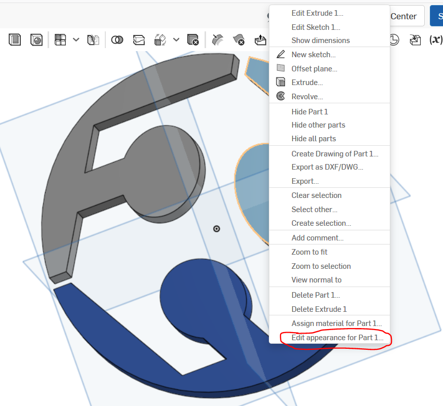
Lastly, to accomplish the set goal, I changed the appearance of the part designs to the suitable colours. Thus I achieved the goal of creating a 3D design of the FabLab Logo from 2D.

Mission Accomplished!
CAD Design of Potential Final Project (Fusion 360)
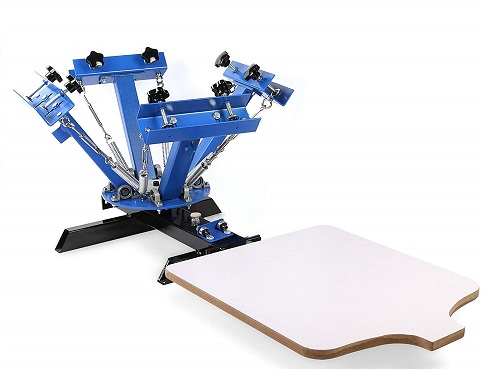
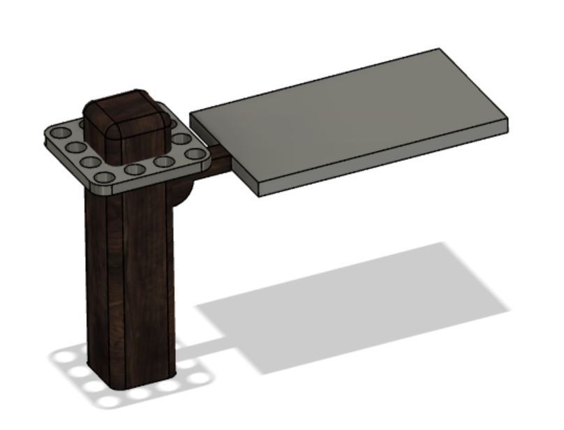
A little information about CAD drawing has been given on the section explaining the focus of this documentation. To show what I accomplished this week, I attempted to make a CAD model of one of the proposed projects 'Fab Mode'. Fab Mode aims to make an advanced open source screen printing machine based on the design depicted in the picture below.
From 2D to CAD (Design of Fab Mode)
Based on the quote that says 'a journey of a thousand mile begins with one single step', the same almost apply to CAD drawing. In that the journey to an effective CAD designing mostly start from it predecessor (2D drawing). Through pictorial representations, I will explain a bit of how I did the 2D drawing of Fab Mode in Fusion 360 here. In case you missed how to launch and create your first 2D design in Fusion 360, please go to this link .
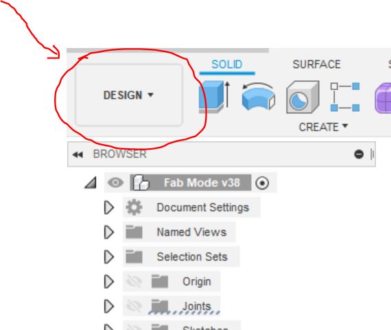
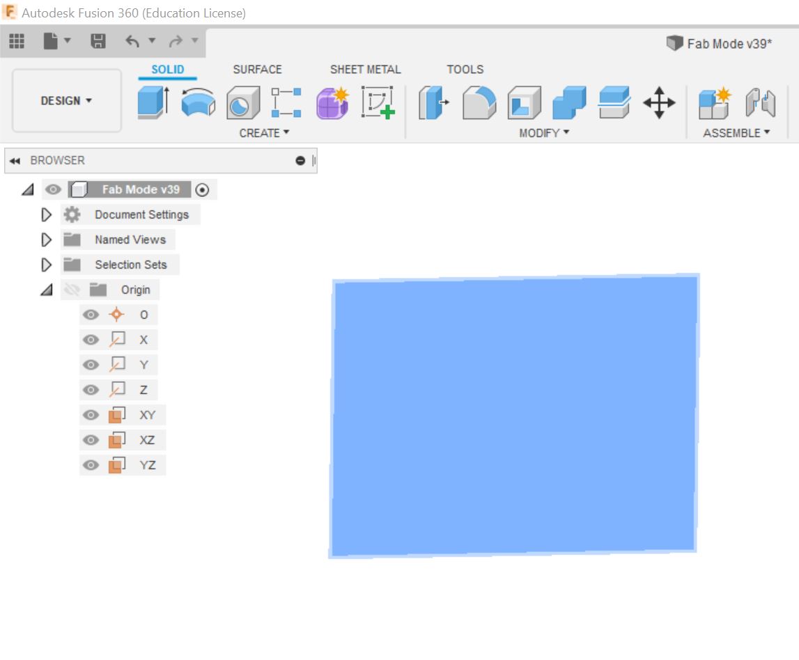
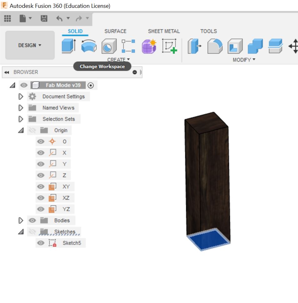
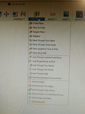
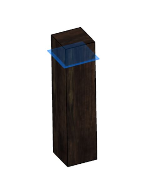
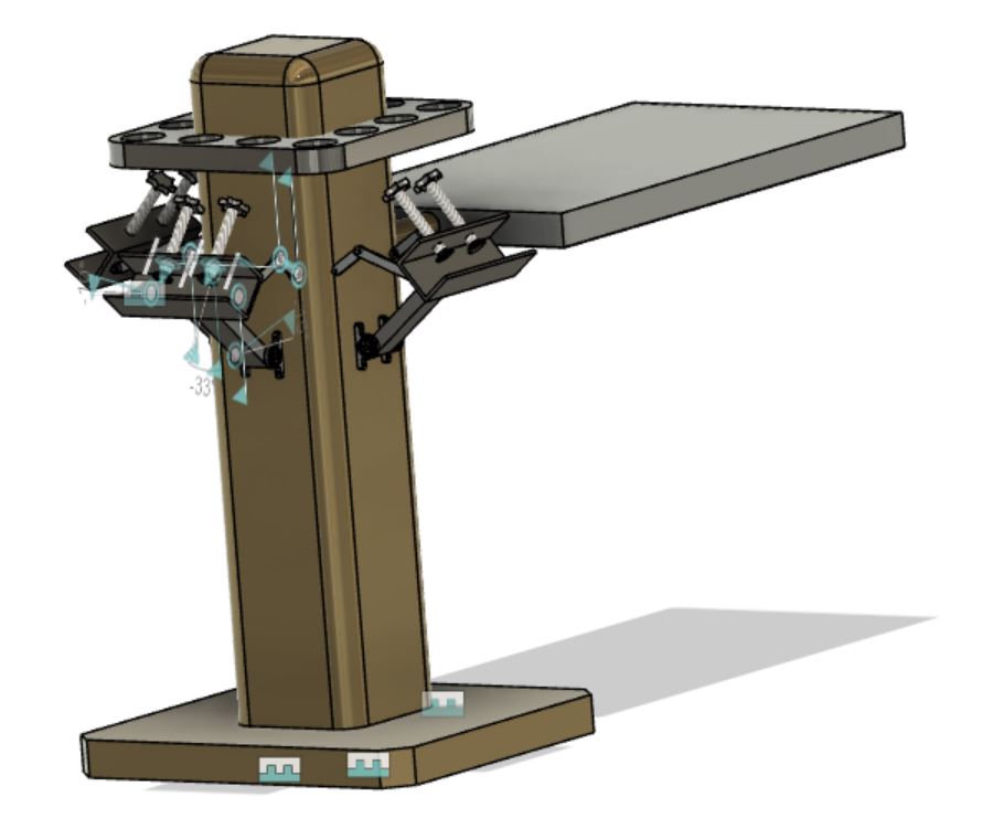
To do the 2D drawing, open Fusion 360 and sign into your account. Ensure that you are on the 'Design' tab as depicted in the diagram below. After this, I started by first creating the pole for Fab Mode. Which means a 2D square was drawn, then I extruded, after which I used the 'Offset Plane' option which can be found on the construct menu to create a plane at which the colour palette would stand. The same method was used to create the Heating panel. You can preview the pictures below to get a vivid understanding of the steps so far.
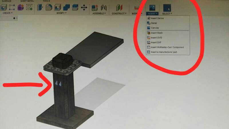
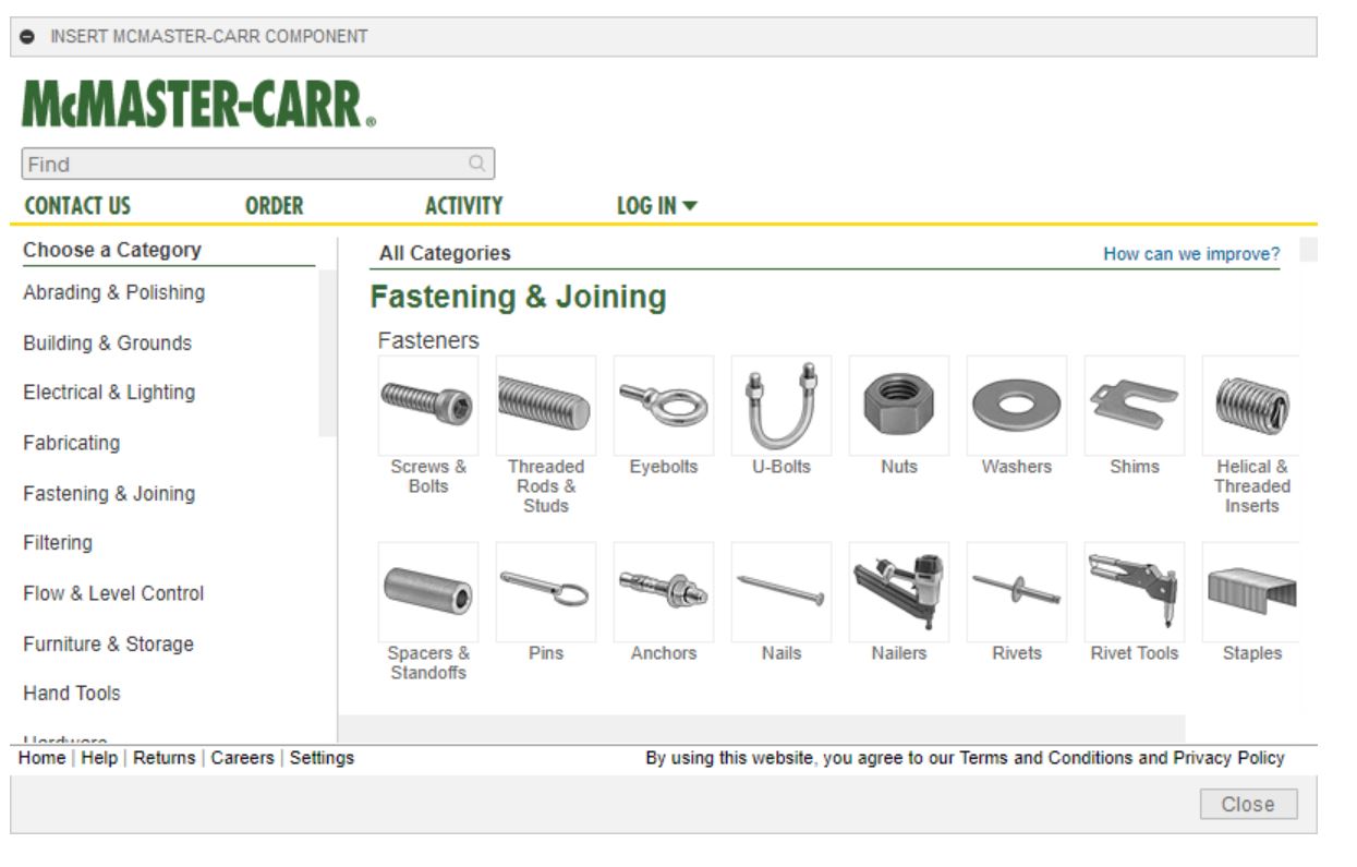
To get the ball bearing used for the rotary of the mesh. I simply clicked on the 'Insert' menu, then I selected 'Insert McMaster-Carr Component'. You will be taken to another (see picture below), then you just need to search for the name of the component you would like to insert. I must warn you that I am not sure these components inserted can be animated, because I really struggled animating them, I had to resolve to designing some components myself.
After all these, I now created the holder for the mesh (see picture below). When satisfied with all the parameters, I simply copied, pasted and rearranged the remaining two mesh holders on the side of the poles.
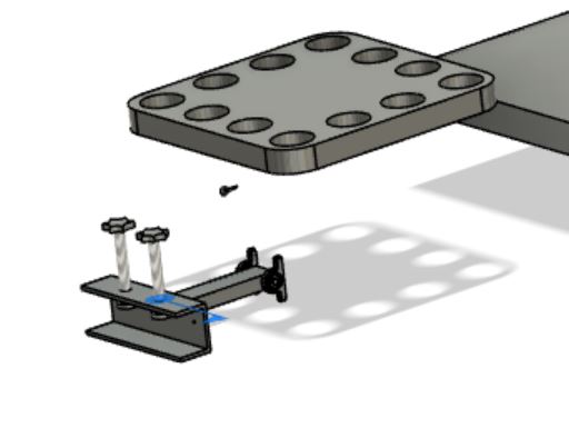
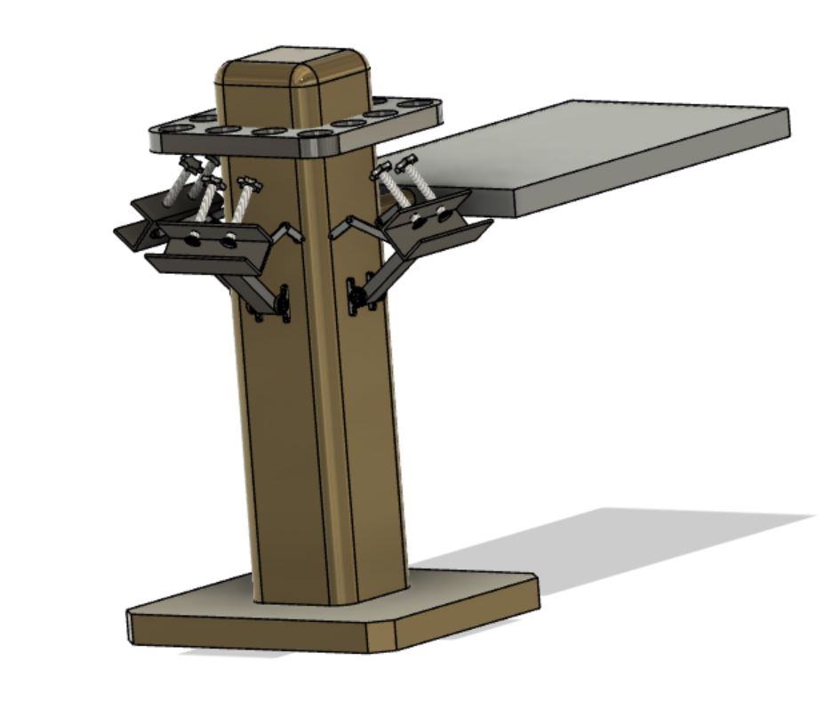
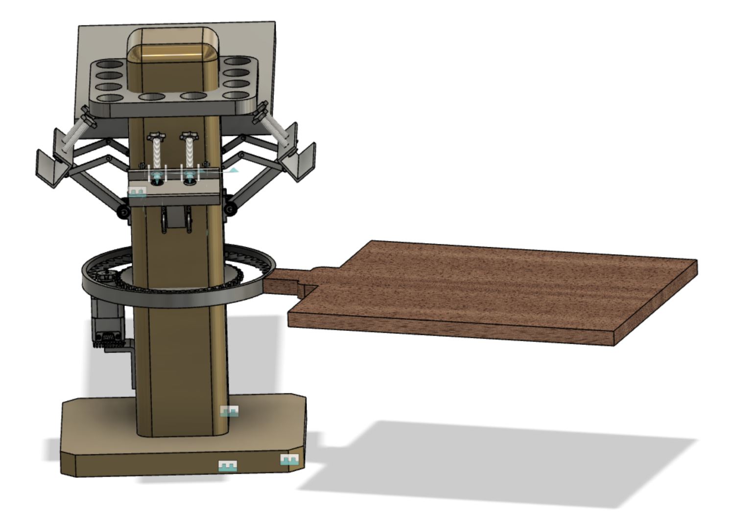
The next thing I did was to animate some of the joints, which includes the joints of the mesh holders, and the connection between the mesh holders and the pole (Ball bearing). Then I inserted a bearing and stepper motor from 'McMaster Components'. All these details has also been depicted in the pictures below.
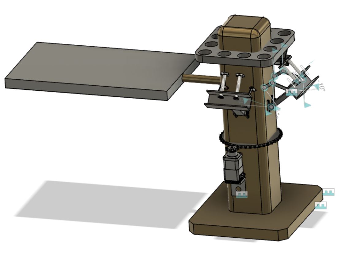
As mentioned earlier, inserting components despite being extremely time-saving, I noticed it also has it own disadvantage. The major disadvantage I noticed is that one could not animate the inserted components. So since I needed to do a little animation on the final components of the CAD, I had to create an internal gear from scratch. Thanks to this YouTube tutorial, I was able to create mine. Though not totally perfect, it still serves the intended purpose.
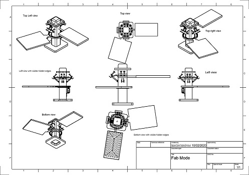
Technical Drawing of Fab Mode
The Technical drawing of the proposed Final project is given below. To do technical drawing I assume you are also using Fusion 360. So you first need to draw your 3D model, then click on the design tab (see diagram above), scroll down to Technical drawing. Then select from design.
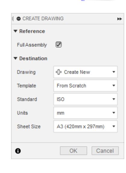
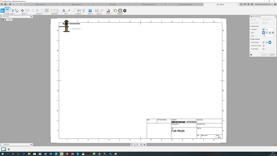
After which you can now select the size of the drawing, whether A3, A4 and so on. If you want to work on an existing technical drawing, select the name of the drawing by clicking the tab infront of 'Drawing'. However, since this study assumes you are just doing this for the first time, then you do not need to worry about that. Just select the sheet size and click 'OK'. Then you should see something like the picture shown below.
Download File (Compressed)
The designs can be downloaded by clicking HERE