'Even if a person has no money, their stomach would still ask for food.'
African Proverbs
Input Devices
Just like other assignments, this week we also have a combination of group and individual assignments to complete.
Group Assignment
Probe an input device's analog levels and digital signals.
You can view the Group Assignment on this Link.
Individual Assignment
The individual assignment are as follow:
Individual Assignment
To do this assignment, I basically modified the existing board I designed in Week6. You can revisit that week's assignment by clicking HERE. One modification I made to the Hello board is to add a PIR sensor to the board.
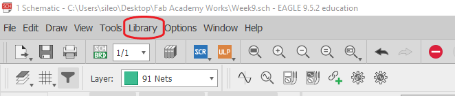
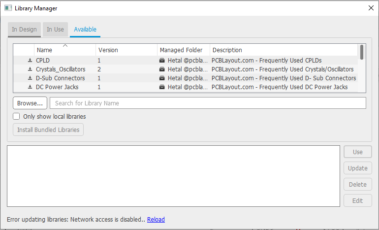
To add the board, I first did a search online for the library file. The internet search led me to this Website where I downloaded the file. After which I navigated to the Library pane to install the downloaded library for the sensor.
After this, I searched for the name of the library I downloaded or you could simply scroll down till you find it, in this case I searched for 'diy-modules'. Then I downloaded all the libraries that I felt would have the parts needed.
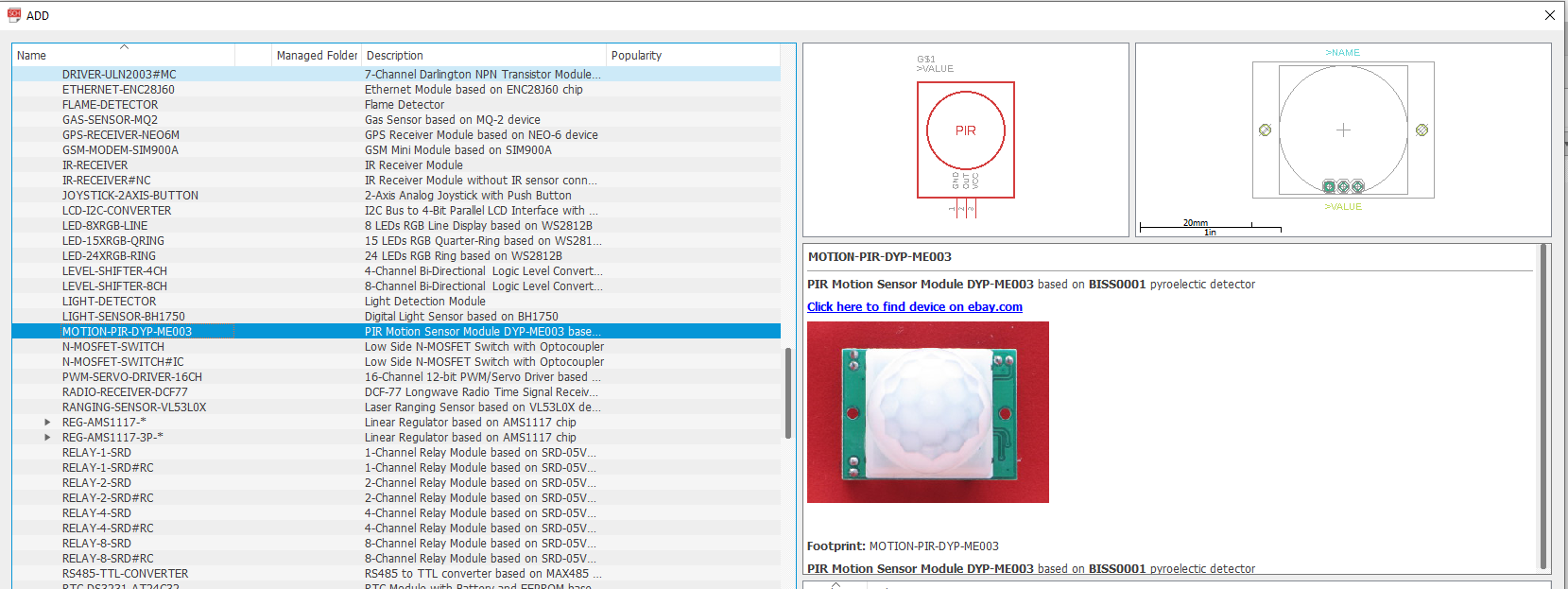
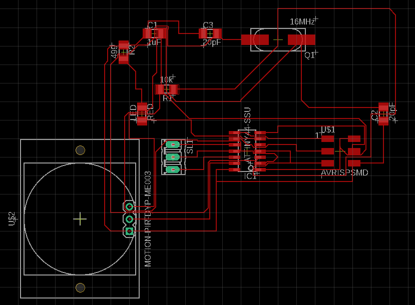
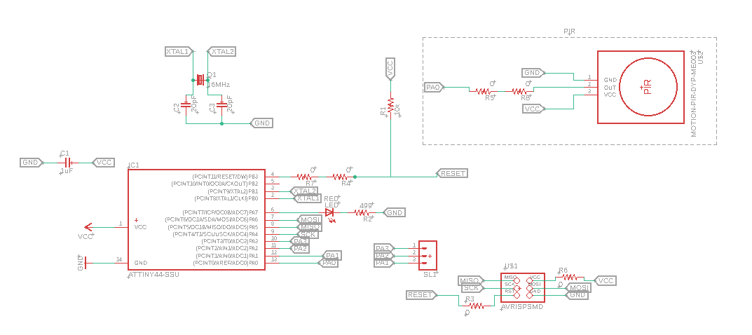
After this, I added the part from the new added library. to the schematic page as depicted in the illustration below.
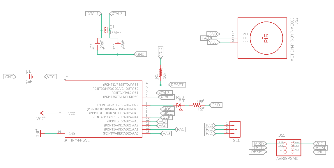
Then I simply connected the pins of the part to the corresponding pins on the circuit. In this case, I connected the VCC to the VCC of the ATTiny44, likewise with the GND pin of the PIR Sensor. Lastly, I connected the 'Out' pin to Port 'PA0'. Please see illustration below.
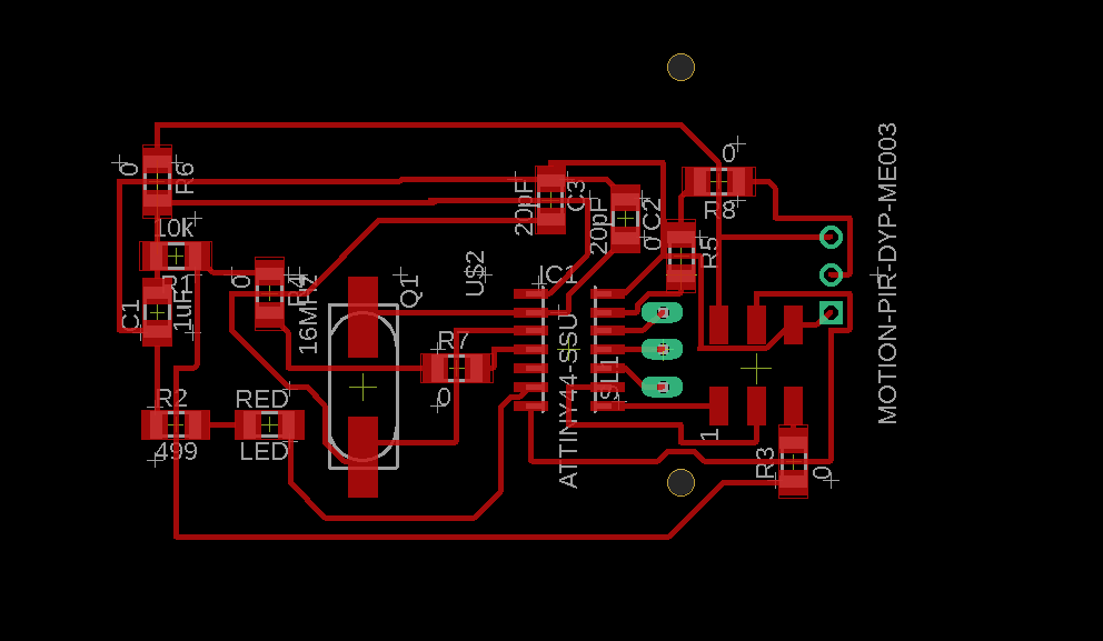
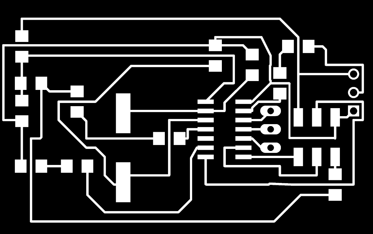
After this, I simply toggled from the schematic page to the board page, so I can design how the board will be fabricated. Below is what the new board with the embedded PIR sensor looks like. Lest I forget, connecting the board is definitely not an easy task. It took me over 12 hours to figure out how to successfully connect one component to the microcontroller. This requires more practice and definitely lots of patience.
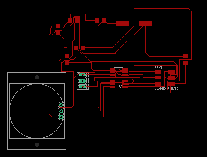
Note: After uploading the file, and review of my Fab instructor. It was revealed that there were some errors with the approach I used to arrange and connect the circuit. One was with the wire width of the design I made. Another was with the way I arranged and passed beneath the components. A typical example is given in the picture below.
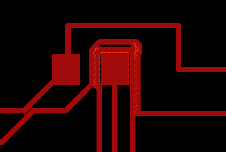
Once again, my silly nature got the best of me. Note:- You can Only pass only one wire underneath another components. Here, I was trying to be a true ambassador of sustainability and fit as much as possible, only for me to be sent right back to reality!
There I thought I had done something good, after having struggled arranging the wire width for couple of days. However, Daniele suggested that I use Zero Ohms resistors in places where it is impossible to bridge. So, the Zero Ohm resistor will now be a new bridge.
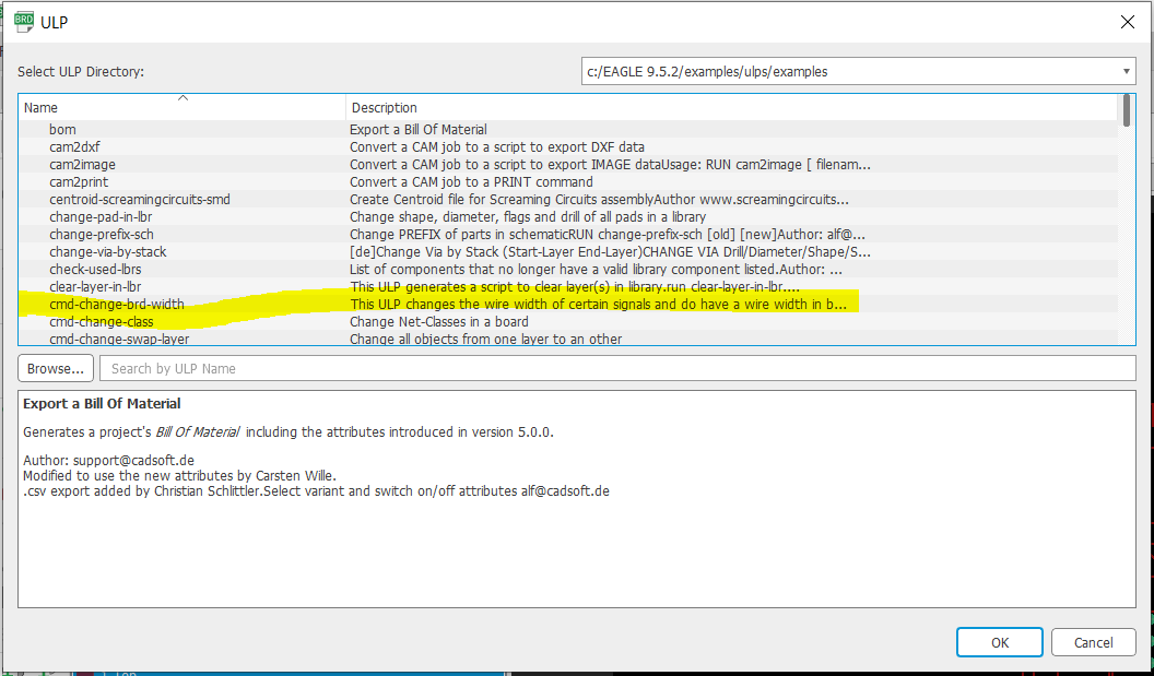
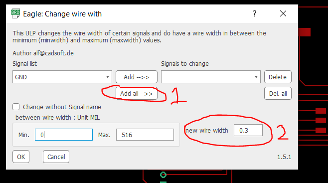
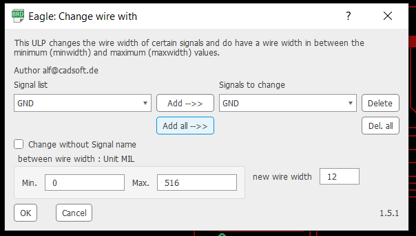
In addition, he also indicated how to change the width all at once without going through the stress of doing that manually and individually. This can be done by going to 'File' -> 'Run ULP' -> 'cmd-change-brd-width' -> 'Add all'. Now you can enter the desired width on the part titled 'new wire width'. After this click 'OK', and all the width will be automatically changed. Please check the pictures below.
After running the ULP script, my design rediscovered a new One thousand ways to die, so I definitely have to modify it with a zillion zero Ohms resistors. I will update the modified version when done.
SOS If you are reading this, please know Mastering the art of 'Making almost anything' is not an easy task.
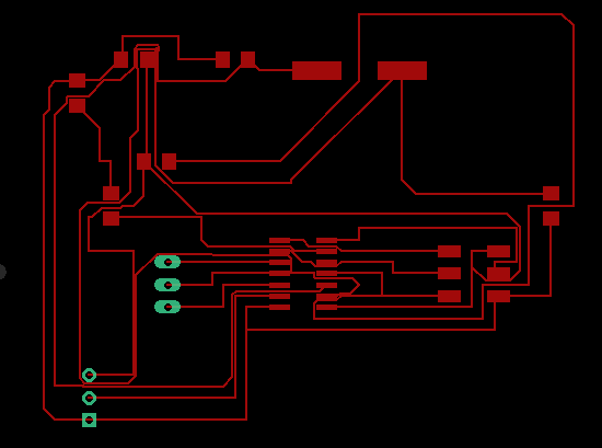
I modified the design, and I must confess that I had to leave it like a troubled water to settle for a while before quenching my thirst of being a master of electronic circuits production. Heeding Daniele's advise came out good. I could not resist the urge to insert lots of 'Zero Ohm' resistors. The pictures below depicts the enjoyable stress I went through to get this done.
After this, I checked with the 'Design Rule Check' (DRC) to ascertain whether everythng is in order. During the check I found this error 'Airwire', which means that one connection is not properly connected. So I fixed that, and I can say I am good to go.
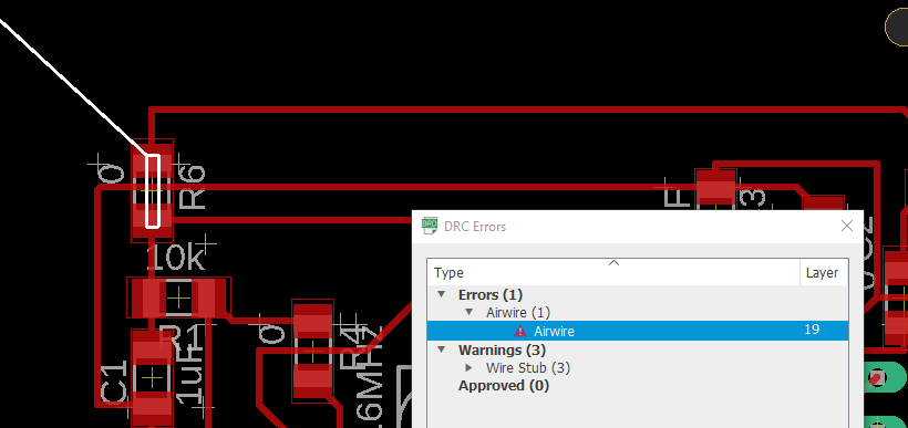
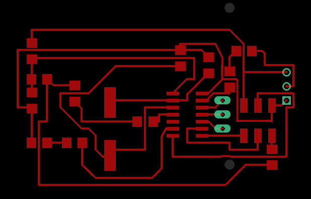
Below is the picture of the new design.
Arduino
Thanks to corona virus invasion, those of us who could not access their labs were allowed to use an Arduino board to show a working version of their project. So, this section will explain the functioning version of my project.
As can be seen below, the example worked on includes two sensors. One is the PIR sensor which was integrated to the electronic board I designed. In addition to this, I also included a distance (Ultrasonic HC-04) sensor in this example.
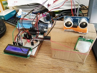
What I did was to first test out the different sensors separately. Below you will find the codes for the PIR sensors.
          #include  // includes the LiquidCrystal Library
          LiquidCrystal lcd(12, 11, 6, 5, 4, 3); // Creates an LCD object. Parameters: (rs, enable, d4, d5, d6, d7)
          const int trigPin = 8;
          const int echoPin = 9;
          long duration;
          int distanceCm;
          int Inches;
          void setup() {
          lcd.begin(16,2); // Initializes the interface to the LCD screen, and specifies the dimensions (width and height) of the display
          pinMode(trigPin, OUTPUT);
          pinMode(echoPin, INPUT);
          }
          void loop() {
          digitalWrite(trigPin, LOW);
          delay(20);
          digitalWrite(trigPin, HIGH);
          delay(10);
          digitalWrite(trigPin, LOW);
          duration = pulseIn(echoPin, HIGH);
          distanceCm= duration*0.034/2;
          Inches = duration*0.0133/2;
          lcd.setCursor(0,0); // Sets the location at which subsequent text written to the LCD will be displayed
          lcd.print("Distance: "); // Prints string "Distance" on the LCD
          lcd.print(distanceCm); // Prints the distance value from the sensor
          lcd.print(" cm");
          delay(10);
          lcd.setCursor(0,1);
          lcd.print("Distance: ");
          lcd.print(Inches);
          lcd.print("inch");
          delay(10);
          }
Below is the first video for the PIR sensor only
Below is the first video for the PIR sensor and Ultrasonic sensor only
          #include

          #include


          LiquidCrystal lcd(12, 11, 6, 5, 4, 3);  // set the LCD address to 0x27 for a 16 chars and 2 line display

          //Initializing the global variables for the distance sensor
          const int trigPin = 8;
          const int echoPin = 9;
          long duration;
          int distanceCm;
          int Inches;


          //Initializing the global variables for PIR sensor
          int RedLED = 13;
          int PIRsensor = 2;
          int PIRState = false;

          int Value = 0;

          void setup()
          {

            // For Distance sensor
            pinMode(trigPin, OUTPUT);
            pinMode(echoPin, INPUT);


            // For PIR sensor
            pinMode(RedLED, OUTPUT);
            pinMode(PIRsensor, INPUT);

            Serial.begin(9600);

            lcd.begin(16,2);
            delay(1000);

            // Print a message to the LCD.
             lcd.setCursor(0,0);
            lcd.print("1 = Dist, 2 = PIR");
            delay(2000);
            lcd.setCursor(0,1);
            lcd.print("Test 1.0");
            lcd.clear();
            delay(2000);

          }


          void loop()
          {
           /* int Message = Serial.write("Please enter 1 or 2");
            Value = Serial.read();

            int Value1 = 1, Value2 = 2; */

           {
           // if (Value == Value1) {
            digitalWrite(trigPin, LOW);
            delay(20);
            digitalWrite(trigPin, HIGH);
            delay(10);
            digitalWrite(trigPin, LOW);
            duration = pulseIn(echoPin, HIGH);
            distanceCm= duration*0.034/2;
            Inches = duration*0.0133/2;
            lcd.setCursor(0,0); // Sets the location at which subsequent text written to the LCD will be displayed
            lcd.print("Distance: "); // Prints string "Distance" on the LCD
            lcd.print(distanceCm); // Prints the distance value from the sensor
            lcd.print(" cm");
            delay(50);
            }


            int PIRValue = digitalRead(PIRsensor); // This syntax reads the input from Pin 2

             // if (Value == Value2) {
              if(PIRValue == HIGH) { // condition to verify whether the inout is on
              digitalWrite(RedLED, HIGH);
             // if (PIRState == false) {
              lcd.setCursor(0,1);
              lcd.print("Motion detected");
             //PIRState = true;
             // Serial.println(PIRValue);

              delay(1000);
              lcd.clear();
             }
            else {
              digitalWrite(RedLED, LOW);
             // if (PIRState == true) {
             // Serial.println("No object");
              lcd.setCursor(0,1);
              lcd.print("No Motion detected");
            //  }
              delay(1000);
              lcd.clear();

          }

          }
Modified Design
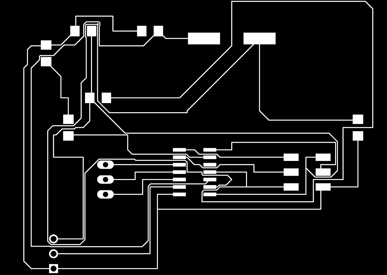
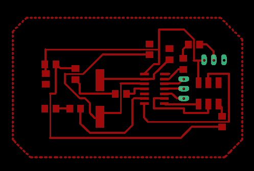
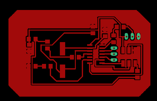
After the lab was opened, I and Daniele revisited the design made for this week's assignment, and modified some silly erros I made in the initial design. One critical thing added was the Ground 'GND' layout. Which means all part that is connected to the ground can be connected to the unused body of the PCB. This will help solve the bridging problem which I annoyingly created during the Electronic Production week. Below are the pictures of the new design. The downloadable files are attached to the download folder below.
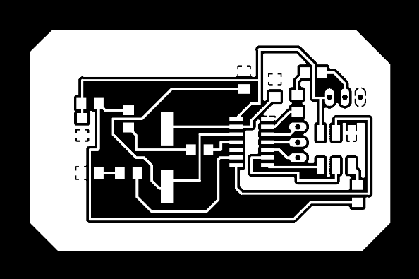
Milling
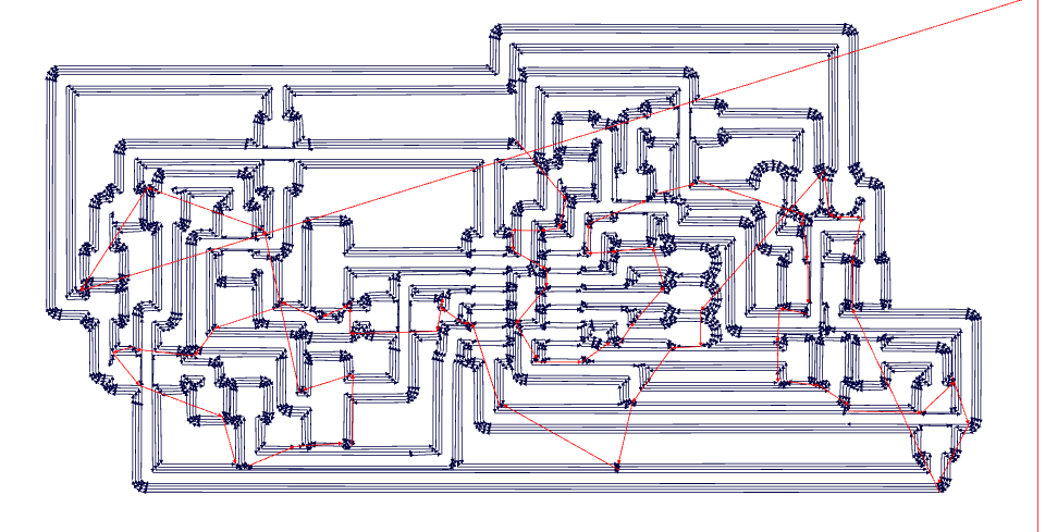
Before milling, ideally one should use Fab Modules to convert the picture outline of the design to GCODE or RML or any other format used by the CNC machine. So the picture below shows how that was done. The trace and outline files for the board can be downloaded HERE.
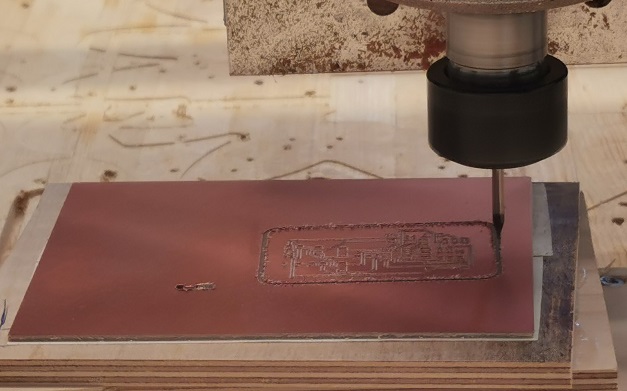
However, I milled the design, using the method used for milling the PCB in Electronic Production. This milling process includes saving the file as a dxf file. Then inserting it into Fusion, converting the dxf file to 2D, then extruding it to the thickness of the PCB board. After which I mill the board. Below are the pictures of the milling process.
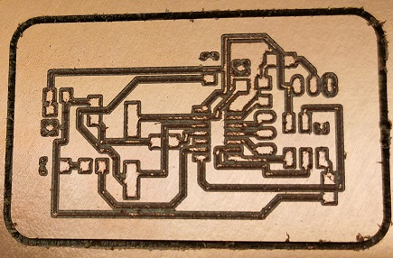
Stuffing
After this I stuffed it up with the components below.
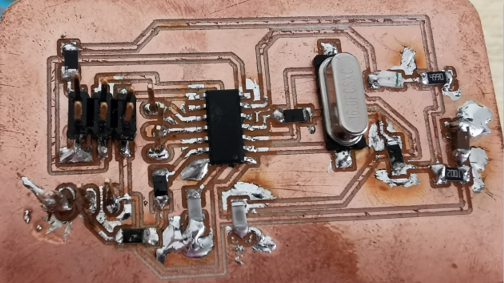
Below is the picture of the stuffed board. Now the next thing is to program the board.
You can download the files for the board HERE.