Group Assignment: Input devices
Probe an input device(s)'s analog and digital signals
This week, as a group, we used an oscilloscope to study the output signals of a couple of different input devices.
Analog
For this part of the assignment, we built a circuit using the components we would use to make a piece of smart clothing. The microcontroller board was a Lilypad USB Plus. We made a stretch sensor out of a length of conducting rubber and a resistor in a voltage divider configuration.

We connected the oscilloscope leads to the ends of the conducting rubber segment and stretched it cyclically by hand. As we connected the leads, the oscilloscope jumped to 1.0V with about 0.05V of noise. Stretching the sensor and relaxing it caused the voltage to oscillate between the 1.0V and about 1.8V. The movie below illustrates the exercise.
Digital
As a first go at a digital input device, we selected the KY-028 temperature sensor from AZ-Delivery. This little module measures a relative temperature and outputs the analog value on one pin, and then compares the value to a threshold, outputting a digital high or low to indicate which side of the threshold the measurement is on.
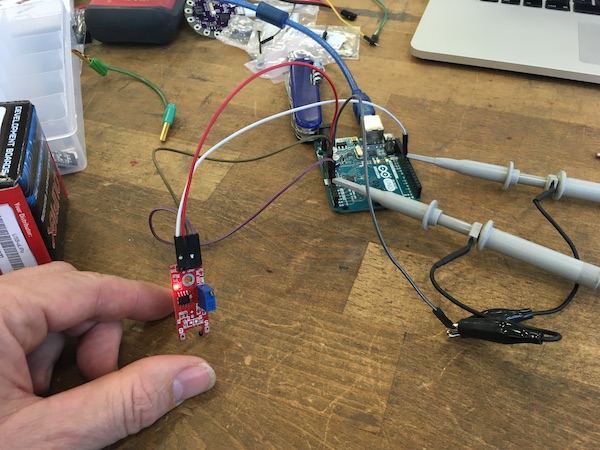
To do the measurement, we powered the module from the 5V supply of an Arduino Uno, which we set up to measure the analog signal on pin 10 and the digital signal on pin A0. We then connected the probes of the oscilloscope’s two channels to the analog and digital outputs of the temperature module. The set up is shown below.
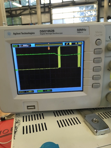
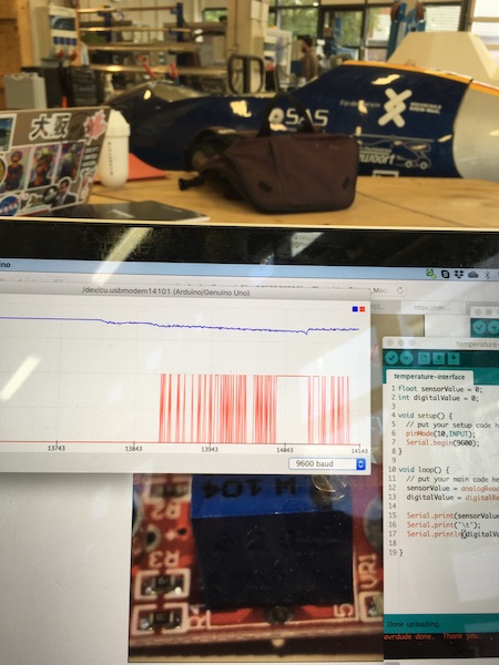
When the temperature sensor was pinched between thumb and forefinger, the analog value dropped and as it passed the threshold, the digital signal bounced to the other state, then finally held that, as shown in the traces below (oscilloscope on the left, Arduino plotter on the right).