'Friendship is made of like minds and like characteristics.'
African Proverbs
Networking Communication
This week we were tasked to conduct two assignments: Group assignment, and an individual assignment. These are listed in this page.
Group Assignment
Send a message between two projects
You can view the Group Assignment on this Link.
Individual Assignment
This week's individual assignment entails: to design, build and connect wired or wireless node(s) with network or bus addresses.
The plan I had for this week's assignment is to create a door unlocking device that does:
Though this is not contributing to my final project. However, it still provides another opportunity to provide another service with the project. So in theory, two NRF24L01 modules will communicate with each other. One will serve as the transmitter connected to the MLX90614, Pyroelectric sensor, and the LED. The receiver will be connected to the Servo motor, which is used to depict the door lock.
Simple Tests
Before proceeding with the task at hand, I decided to do a quick test of some of the components I acquired, this include the NRF24L01 transceiver module, HC 05 bluetooth module, Arduino UNO WiFi, and NodeMCU. I will be showing the tests and the components tested below.
I know Neil always mentions the phrase 'Document while you work', which I have faithfully adhered to up to so far. But that phrase hit a meteorite while trying to establish a communication between the NRF24L01 module I bought for this weeks assignment. If I had documented while working, you would have seen a lot of curse words, because the crazy component wouldn't just communicate with each other. However, I believe it is vital we document while we work, except on situations that are beyond your reach like mine.
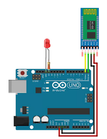
HC 05 Bluetooth Module
To test my Bluetooth module, I decided to try out this EXAMPLE. The Pinout configuration of the example as well as the schematic are given below.
Arduino Pins Bluetooth Pins
RX (Pin 0) ———-> TX
TX (Pin 1) ———-> RX
5V ———-> VCC
GND ———-> GND
Code
               /*
               This is a code adapted from Mayoogh Girish (Bluetooh Basic: LED ON OFF)
               */

               char Incoming_value = 0;                //Variable for storing Incoming_value
               void setup()
               {
                 Serial.begin(9600);         //Sets the data rate in bits per second (baud) for serial data transmission
                 pinMode(13, OUTPUT);        //Sets digital pin 13 as output pin
               }
               void loop()
            {
              if(Serial.available() > 0)
            {
              Incoming_value = Serial.read();      //Read the incoming data and store it into variable Incoming_value
              Serial.print(Incoming_value);        //Print Value of Incoming_value in Serial monitor
              Serial.print("\n");        //New line
              if(Incoming_value == '1')            //Checks whether value of Incoming_value is equal to 1
                digitalWrite(13, HIGH);  //If value is 1 then LED turns ON
              else if(Incoming_value == '0')       //Checks whether value of Incoming_value is equal to 0
                digitalWrite(13, LOW);   //If value is 0 then LED turns OFF
            }

          }
Thanks to Mayoogh Giris and all others that have taken their time to make useful tutorials. You can find the video of my test appended below.
NRF24L01 Module
The thing about my Fab Academy journey lies mostly on resilience, self-believe and support from an intelligent Fab Guru. I initially bought a pack of 10 NRF24L01 from Amazon and none failed to transmit anything reasonable but frustration and fatigue to my already beaten body. So I sent it back and ordered another pack from a different seller. So after waiting for a long time for my courage to be rebuild so as to tackle it. I resumed work on this assignment. Below you will find a quick test I made to verify whether the new NRF24L01 functions properly.
I extracted a sample from the, Arduino forum. This example was developed by a user called Robin2. So I will use this opportunity to say a quick shoutout to Robin2 for his selflessness. To my relief, the code worked smoothly. Below you can find the codes below and the video depicting the working example.
Simple Tranmitter Test
              /*
          - CONNECTIONS: nRF24L01 Modules See:

          http://arduino-info.wikispaces.com/Nrf24L01-2.4GHz-HowTo
            1 - GND
            2 - VCC 3.3V !!! NOT 5V
            3 - CE to Arduino pin 8 // I changed this to 8 because I have already used Port 9 for the servo motor for the real test
            4 - CSN to Arduino pin 10
            5 - SCK to Arduino pin 13
            6 - MOSI to Arduino pin 11
            7 - MISO to Arduino pin 12
            8 - UNUSED

          When working properly the Rx program should show "Data received Message n" in which n varies from 0 to 9. This should be printed at about one second intervals.
          */

          // SimpleTx - the master or the transmitter

          #include
          #include
          #include


          #define CE_PIN   8
          #define CSN_PIN 10

          const byte slaveAddress[5] = {'R','x','A','A','A'};


          RF24 radio(CE_PIN, CSN_PIN); // Create a Radio

          char dataToSend[10] = "Message 0";
          char txNum = '0';


          unsigned long currentMillis;
          unsigned long prevMillis;
          unsigned long txIntervalMillis = 1000; // send once per second


          void setup() {

              Serial.begin(9600);

              Serial.println("SimpleTx Starting");

              radio.begin();
              radio.setDataRate( RF24_250KBPS );
              radio.setRetries(3,5); // delay, count
              radio.openWritingPipe(slaveAddress);
          }

          //====================

          void loop() {
              currentMillis = millis();
              if (currentMillis - prevMillis >= txIntervalMillis) {
                  send();
                  prevMillis = millis();
              }
          }

          //====================

          void send() {

              bool rslt;
              rslt = radio.write( &dataToSend, sizeof(dataToSend) );
                  // Always use sizeof() as it gives the size as the number of bytes.
                  // For example if dataToSend was an int sizeof() would correctly return 2

              Serial.print("Data Sent ");
              Serial.print(dataToSend);
              if (rslt) {
                  Serial.println("  Acknowledge received");
                  updateMessage();
              }
              else {
                  Serial.println("  Tx failed");
              }
          }

          //================

          void updateMessage() {
                  // so you can see that new data is being sent
              txNum += 1;
              if (txNum > '9') {
                  txNum = '0';
              }
              dataToSend[8] = txNum;
          }
Simple Receiver Test
            /*
        - CONNECTIONS: nRF24L01 Modules See:

        http://arduino-info.wikispaces.com/Nrf24L01-2.4GHz-HowTo
          1 - GND
          2 - VCC 3.3V !!! NOT 5V
          3 - CE to Arduino pin 8
          4 - CSN to Arduino pin 10
          5 - SCK to Arduino pin 13
          6 - MOSI to Arduino pin 11
          7 - MISO to Arduino pin 12
          8 - UNUSED

        Receive a series of messages containing random numbers between 1 and 9 from the sender radio.
        */


        // SimpleRx - the slave or the receiver

        #include
        #include
        #include

        #define CE_PIN   8
        #define CSN_PIN 10

        const byte thisSlaveAddress[5] = {'R','x','A','A','A'};

        RF24 radio(CE_PIN, CSN_PIN);

        char dataReceived[10]; // this must match dataToSend in the TX
        bool newData = false;

        //===========

        void setup() {

            Serial.begin(9600);

            Serial.println("SimpleRx Starting");
            radio.begin();
            radio.setDataRate( RF24_250KBPS );
            radio.openReadingPipe(1, thisSlaveAddress);
            radio.startListening();
        }

        //=============

        void loop() {
            getData();
            showData();
        }

        //==============

        void getData() {
            if ( radio.available() ) {
                radio.read( &dataReceived, sizeof(dataReceived) );
                newData = true;
            }
        }

        void showData() {
            if (newData == true) {
                Serial.print("Data received ");
                Serial.println(dataReceived);
                newData = false;
            }
        }
Circuit Design
This section will cover the electronic design for this assignment. I will design 2 different circuit boards, one as a receiver and the other as a transmitter. The receiver will use ATTiny84 microcontroller, while the transmitter will use ATMEGA328P due to the numbers of pins needed for the functionalities of the circuit board.
Receiver
Below are the Eagle design of the circuit board for the receiver.

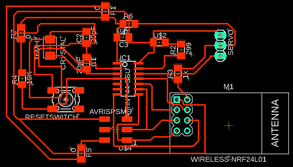
Transmitter
Below are the Eagle design of the circuit board for the transmitter.
You can download the Schematic of the electronic board HERE, or go to the download section of this page.
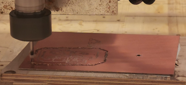
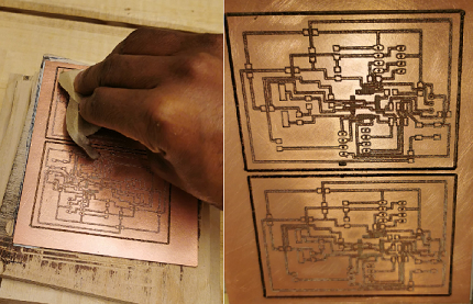
Milling
I proceeded with the milling process. This is depicted through the series of pictures below.
After which I stuffed it
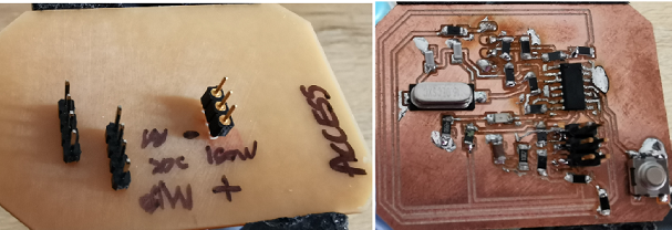
Then I also attempted to mill the receiver.
Detour
After facing series of challenges with the milling process. I was unable to finalize the milling of the Receiver module. So I resolved into using Arduino to do a proof of concept. This will be presented below. However, I intend to update this assignment with the working version of the module once I managed to mill it.
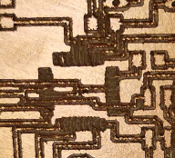
The problem is because my endmill was unable to mill the space required for ATMEGA328, so It kept chipping off the copper layout of the board. This can be seen in the picture below.
Code
The real code and working model of the device will be uploaded as soon as the lockdown is eased and my lab is back in operation. However, the Arduino version of the device will be given below.
So I also made changes to the design. I struggled to get the Servo Motor cooperate. So I just used the console instead. This can be seen in the video below.
Fab Transmitter
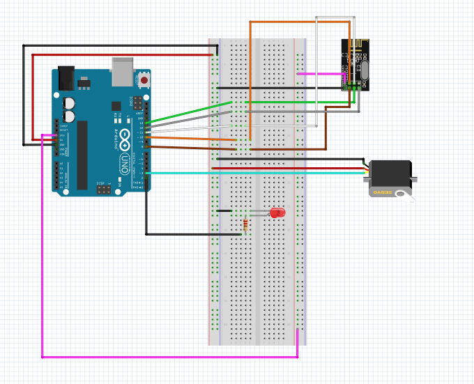
A pictorial sketch of the Fab Transmitter and the receiver can be seen below. It is similar to the sketch used by Robin2 in the Arduino forum.

Below is the sketch of the receiver.
             // Library for Temperature sensor
        #include
        #include

        //Calling the library for NRF24L01 sensor
        #include
        #include
        #include

        #define CE_PIN   8 // This object represents a modem connected to the Arduino
        #define CSN_PIN 10 // Arguments 8 and 10 are the digital pin numbers to which signals CE, CSN are connected

        const byte slaveAddress[5] = {'C','O','V','I','D'}; //Byte of array representing the address. This is the address where we will send the data. This should be same on the receiving side.


        RF24 radio(CE_PIN, CSN_PIN); // Create a Radio

        Adafruit_MLX90614 mlx = Adafruit_MLX90614();

        //This initializes the PIR sensor to port 5
        int PIR_pin = 5;

        //This initializes the LED to port 2
        int Led_pin = 3;

        char Switch[6] = "Open";
        char Switch1[6] = "Close";
        char Switch11[10] = "Nothing";

        float Temp = 38.0;

        int PIR_state = 0;

        void setup() {

          pinMode(PIR_pin, INPUT);
          pinMode(Led_pin, OUTPUT);

          Serial.begin(9600); // Starting serial communication

          radio.begin();                  //Starting the Wireless communication
          radio.openWritingPipe(slaveAddress); //Setting the address where we will send the data
          radio.setDataRate( RF24_250KBPS );
          radio.setRetries(3,5); // delay, count
          radio.stopListening();          //This sets the module as transmitter

          mlx.begin(); //Starts the Temperature sensor
        }

        void loop() {

          PIR_state = digitalRead(PIR_pin);

          float SensorState = mlx.readObjectTempC();

          if((PIR_state == HIGH) && (SensorState <= Temp))
          {
            digitalWrite(Led_pin, HIGH);
            radio.write(&Switch, sizeof(Switch)); //Sending the message to receiver
           delay(1000);
           }

          else if((PIR_state == LOW) && (SensorState <= Temp))
          {
            digitalWrite(Led_pin, LOW);
            radio.write(&Switch11, sizeof(Switch11)); //Sending the message to receiver
           delay(1000);
           }

          else
          {
            digitalWrite(Led_pin, LOW);
            radio.write(&Switch1, sizeof(Switch1)); //Sending the message to receiver
          }

        }
What this device does is
Fab Receiver
             //Calling the library for NRF24L01 sensor
        #include
        #include
        #include

        #define CE_PIN   8 // This object represents a modem connected to the Arduino
        #define CSN_PIN 10 // Arguments 8 and 10 are the digital pin numbers to which signals CE, CSN are connected

        const byte thisSlaveAddress[5] = {'C','O','V','I','D'}; //Byte of array representing the address. This is the address where we will send the data. This should be same on the receiving side.


        RF24 radio(CE_PIN, CSN_PIN); // Create a Radio

        char Switch[6]; // this must match Switch in the TX
        char Switch1[6]; // this must match Switch1 in the TX
        char Switch11[10];

        //This initializes the LED to port 2
        int Led_pin = 2;

        boolean PIR_state = 0;

        void setup() {

          pinMode(Led_pin, OUTPUT);

          Serial.begin(9600);
          Serial.println("SimpleRx Starting");

          radio.begin();
          radio.openReadingPipe(1, thisSlaveAddress); //Setting the address at which we will receive the data
          radio.setDataRate( RF24_250KBPS );
          radio.startListening(); //This sets the module as receiver

        }

        void loop()
        {
          if (radio.available())              //Looking for the data.
        {

          digitalWrite(Led_pin, HIGH);

            Serial.println(Switch);
            radio.read(&Switch, sizeof(Switch));    //Reading the data
            delay(1000);
          }

          else
          {
            digitalWrite(Led_pin, LOW);
            radio.read(&Switch11, sizeof(Switch11));
            radio.read(&Switch1, sizeof(Switch1));    //Reading the data
            Serial.println(Switch1);}
            delay(1000);
          }
I will still modify this later. Hopefully as soon as I am done with the development of my final project.
Modified and Functioning
So, on Sunday 12.07.2020, after consulting my friend Jorge Montalvo (another fab Guru), I was able to make the code above work properly. That was not after Jorge rearranged my code just to show how bad of a programmer I was. You can find the rearranged code below as well as the video to show that it is working.
     // Library for Temperature sensor
        #include
        #include

        //Calling the library for NRF24L01 sensor
        #include
        #include
        #include
        //#include

        #define CE_PIN   8 // This object represents a modem connected to the Arduino
        #define CSN_PIN 10 // Arguments 8 and 10 are the digital pin numbers to which signals CE, CSN are connected

        const byte slaveAddress[5] = {'C','O','V','I','D'}; //Byte of array representing the address. This is the address where we will send the data. This should be same on the receiving side.


        RF24 radio(CE_PIN, CSN_PIN); // Create a Radio

        Adafruit_MLX90614 mlx = Adafruit_MLX90614();

        //This initializes the PIR sensor to port 5
        int PIR_pin = 5;

        //This initializes the LED to port 2
        int Led_pin = 3;

        char Switch[6] = "Open";
        char Switch1[6] = "Close";
        char Switch11[10] = "Nothing";

        float Temp = 38.0;

        int PIR_state = 0;

        void setup() {

          pinMode(PIR_pin, INPUT);
          pinMode(Led_pin, OUTPUT);

          Serial.begin(9600); // Starting serial communication

          radio.begin();                  //Starting the Wireless communication
          radio.openWritingPipe(slaveAddress); //Setting the address where we will send the data
          radio.setDataRate( RF24_250KBPS );
          radio.setRetries(3,5); // delay, count
          radio.stopListening();          //This sets the module as transmitter

          mlx.begin(); //Starts the Temperature sensor
          Serial.println("SimpleTx Starting");

        }

        void loop() {

          PIR_state = digitalRead(PIR_pin);

          float SensorState = mlx.readObjectTempC();

        if(PIR_state==LOW){
           if (SensorState <= Temp) {
            Serial.println(SensorState);
            digitalWrite(Led_pin, LOW);
            radio.write(&Switch11, sizeof(Switch11)); //Sending the message to receiver
            Serial.println(Switch11);
            delay(1000);
           }else  {
            digitalWrite(Led_pin, LOW);
            radio.write(&Switch11, sizeof(Switch11)); //Sending the message to receiver
          }}else if (SensorState <= Temp) {
           Serial.println(SensorState);
            digitalWrite(Led_pin, HIGH);
            radio.write(&Switch, sizeof(Switch)); //Sending the message to receiver
            Serial.println(Switch);
            delay(1000);
           }else{
            Serial.println(SensorState);
            digitalWrite(Led_pin, HIGH);
            radio.write(&Switch1, sizeof(Switch1)); //Sending the message to receiver
            Serial.println(Switch1);
            delay(1000);
           }
        }
     //Calling the library for Servo Motor
      #include

      //Calling the library for NRF24L01 sensor
      #include
      #include
      #include

      #define CE_PIN   8 // This object represents a modem connected to the Arduino
      #define CSN_PIN 10 // Arguments 8 and 10 are the digital pin numbers to which signals CE, CSN are connected

      const byte thisSlaveAddress[5] = {'C','O','V','I','D'}; //Byte of array representing the address. This is the address where we will send the data. This should be same on the receiving side.


      RF24 radio(CE_PIN, CSN_PIN); // Create a Radio

      char Switch[6]; // this must match Switch in the TX
      char Switch1[6]; // this must match Switch1 in the TX
      char Switch11[10];
      char Test[10];
      //This initializes the LED to port 2
      int Led_pin = 2;

      // This initializes the servo Motor to port 9
      int ServoPin = 3;

      boolean PIR_state = 0;

      // Create a servo object
        Servo Servo1;

      void setup() {

        pinMode(Led_pin, OUTPUT);

        Serial.begin(9600);
        Serial.println("SimpleRx Starting");

        radio.begin();
        radio.openReadingPipe(1, thisSlaveAddress); //Setting the address at which we will receive the data
        radio.setDataRate( RF24_250KBPS );
        radio.startListening(); //This sets the module as receiver

        // We need to attach the servo to the used pin number
         Servo1.attach(ServoPin);
      }

      void loop(){
         Servo1.write(0);

        if (radio.available())              //Looking for the data.
      {

        digitalWrite(Led_pin, HIGH);
          radio.read(&Switch11, sizeof(Switch11));    //Reading the data
          Serial.println(Switch11);

          if(strcmp(Switch11,"Open")==0){
            Servo1.write(90);
            delay(100);}
          // Make servo go to 90 degrees

        }

        else
        {
          digitalWrite(Led_pin, LOW);
        }
      }
You can follow the progress of the Final project HERE.