Embedded_networking_and_communications
Send a message between two projects
The objective of our group project this week was to send a signal from one project to another. We’ve interpreted that as from one board to another.
Software Serial
Our goal was to communicate between one of our boards, which are all based on the AtTiny84, and a commercial Arduino (Uno or Nano). As the AtTiny84 doesn’t have a built-in serial library, we chose to use the SoftwareSerial library on both machines.
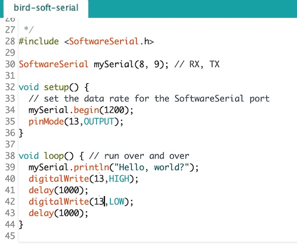
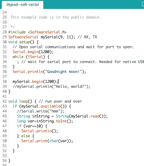
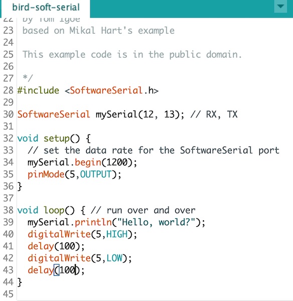
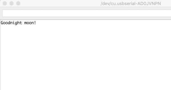
The sketch we used was a modified version of the example, as shown below. The first of the two sketches is the code intended for the sending board, while the second runs on the listener. The sender just continuously sends “Hello, world?” and flashes its LED at one-second intervals. The receiver starts by printing “Goodnight Moon” to the serial monitor, and then repeats the strings it receives over the SoftwareSerial port to the serial monitor, so that the data can be seen on the computer.
Arduino to Arduino
To start off, we used two commercial boards so that we could learn about the software side without the added complication of the self-made hardware.
The boards were wired up like this:
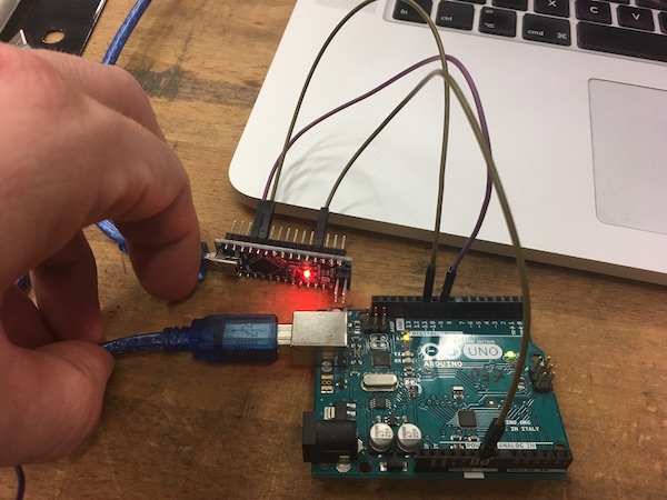
It’s hard to tell from the picture, but the connections are as follows:
| Nano | Uno |
|---|---|
| RX 8 | TX 11 |
| TX 9 | RX 9 |
| GND | GND |
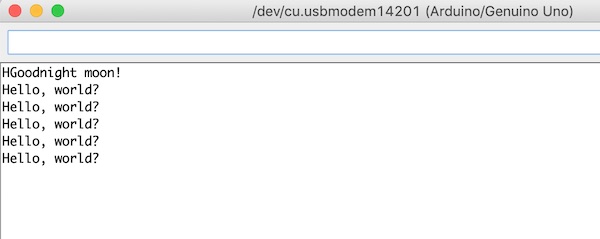
This works fine!
Sketches
Birdboard to Arduino
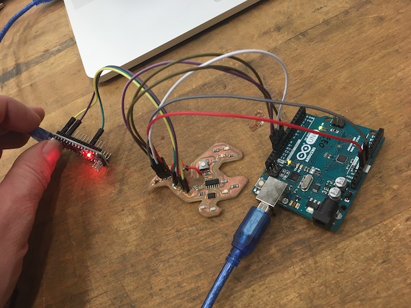
Cheered by the easy win above, we decided to try our own board. The obvious choice is the swan board from an earlier exercise, since it wasn’t busy and had been designed with three pins specifically for serial connection.
This involved one more board, as the swan board has no programmer of its own, so the Arduino Uno was made into an ISP using the example sketch.
The sender sketch had to be modified a bit to use the AtTiny84 pins:
Connections
The connections between the boards were done according to the table below.
| Line | BirdBoard | AtTiny | Arduino Uno | Arduino Nano |
|---|---|---|---|---|
| GND | ISP 1 | Pin 14 | GND | |
| MOSI | ISP 2 | Pin 7 | Pin D11 | |
| Vcc | ISP 3 | Pin 1 | Vcc | |
| MISO | ISP 4 | Pin 8 | Pin D12 | |
| SCK | ISP 5 | Pin 9 | Pin D13 | |
| RST | ISP 6 | Pin 4 | Pin D10 | |
| GND | Ser 1 | Pin 14 | GND | |
| Ser 3 TX | Pin 13 | Pin 9 RX | ||
| Ser 4 RX | Pin 12 | Pin 11 TX |
In reality this looked like this:
It didn’t work. Goodnight moon, but no hello world.
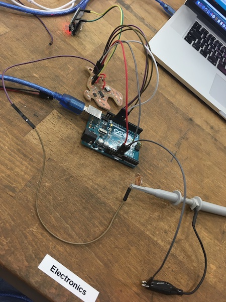
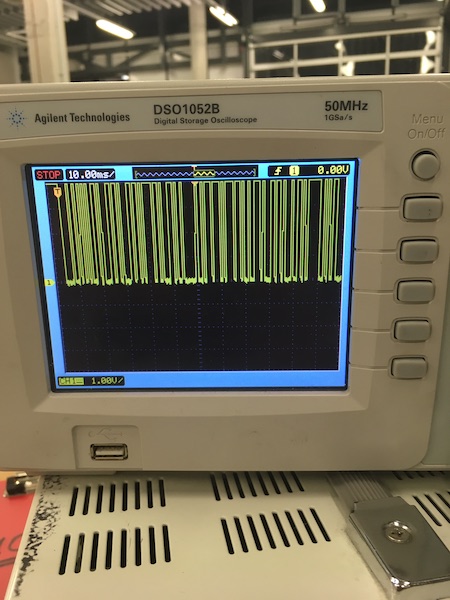
The problem was easy to find in the end. We checked the output of Ser 3 (Pin 13) on the swan board using an oscilloscope:
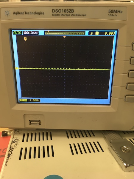
Flat line. No idea why. The LED is flashing to indicate that the sketch is working, but there’s no serial output on the pin. There is continuity between the header pin and the chip pin.
Fixing the problem
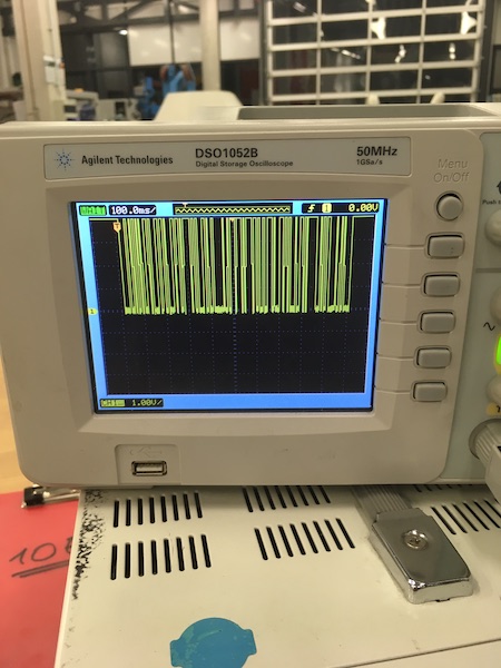
The first part of the problem was quickly solved after a skype discussion with our tutor. Turns out the mapping of the pins in the Arduino IDE is different from the actual physical mapping. A quick bit of renaming in the sending sketch:
SoftwareSerial mySerial(1,0); // RX,TX
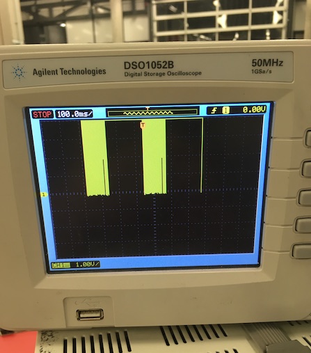
mapped the correct pins to the output and the oscilloscope showed a happy signal:
It wasn’t enough though, as when we tried to read the signal with SoftwareSerial on the Nano, all we got were 128’s and 0’s. There was a pattern to them, but not the “hello, world?” message we’d sent.
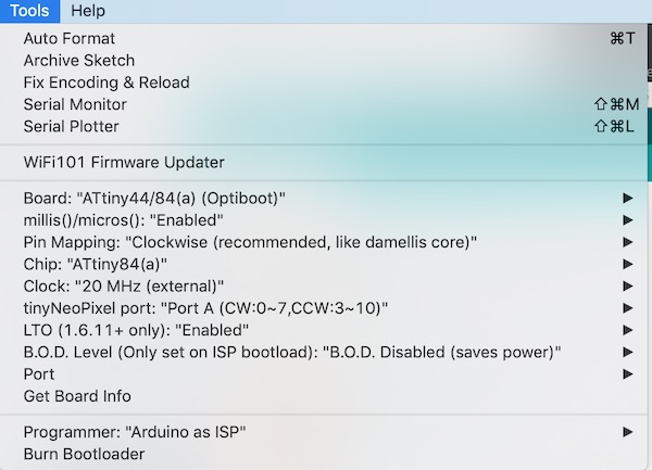
After much head scratching, the problem finally came clear. We had used the wrong libraries to program the AtTiny84 chip. The old library we were using (by Dave Mellick) didn’t properly support SoftwareSerial on this chip. Instead we turned to a newer library by Spence Konde and added the following link to the Arduino IDE Preferences.
http://drazzy.com/package_drazzy.com_index.json
Then we removed the old AtTiny library and installed the new one. The new options are more detailed for the connection to the chip:
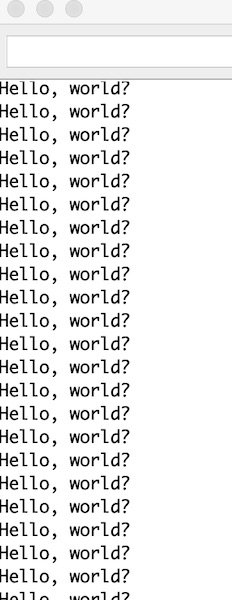
Once the library was installed, we had to “Burn Bootloader” on the AtTiny84, and then use the menu option to “Upload using Programmer”, rather than the usual arrow in the IDE window.
Once we did that, the code uploaded no problem and lo and behold, we got:
When we looked at the oscilloscope trace, we saw what the problem had been. The trace is qualitatively identical, but check out the time divisions (top left corner of the pix below). The old library just wasn’t outputting the signal fast enough, in fact it was ten times too slow, so the poor Nano receiver was only just seeing step changes and interpreting them as 128’s or 0’s.
Addressing
Part of the assignment was to address individual boards separately. We could have done this with I2C or something like it, but we did that in our individual assignments. Here for the group assignment, since the communication is only one-way, we’ve decided to try a receiver-side identification system, with the ID buried in the message.
The design here is that the swan board should send out two messages, each with an identifier at the start. Each of the receiver boards checks the ID code and flashes its LED twice if the ID matches its own. For this we need three sketches, one for the sender (swan board) and one each for the receiver boards (the same sketch, but with a differently set constant).
Sketches
The first sketch runs on the swan board. It is just a minor modification of the “hello, world?” sketch we used earlier.

The other two boards (a Nano and a Lilypad) run the following sketch, with the relevant top three lines commented out depending on the board.
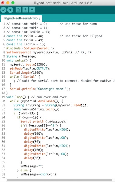
The swan is set up to send two serial commands. The “N1 flash LED” command is for the Nano (board “1”) and the “N2 flash LED” command is for the Lilypad (board “2”).
The sketches are available for download here:
Connection
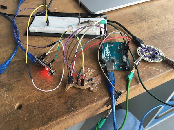
The three boards (and the Uno programmer for the swan board) were connected as shown below. The serial output from the swan board was divided so that it was shared between both the nano and the lilypad.
Success
As the swan sends the first message, the orange LED turns on, and the nano flashes twice to indicate that it’s received its message. When the swan sends the second message, it flashes its green LED once, and the lilypad flashes a white LED twice to say it has received its message.