'Not everyone who chased the zebra caught it, but he who caught it, chased it.'
African Proverbs
Task
The task for this week are divided into tow parts which are stated below:
1. Group Assignment
We were tasked to work as a group to conduct some tests on the cutting settings, and slot dimensions of the laser cutter. To be specific we were asked to characterize your lasercutter's focus, power, speed, rate, kerf, and joint clearance. Though it is well said that a single tree does not make a forest, since I am working remotely, I think I am going to be the first single tree forest or single forest tree (It is quite difficult to express since English is a colonial language to me).
You can view the Group Assignment on this Link.
2. Individual Assignment
Apart from the group assignment listed above, we were also given three individual assignments.
Software
The software I used for this phase of the project are:
Fusion 360
Corel Draw
Group Assignment
As a reminder, kerf is the groove or slit created when the laser cuts any material. When the laser cuts some part of the material desintegrates somehow (e.g. transforming it into powder). This makes the pieces are a little bit smaller than the original design.
Power and speed parameters
The power and speed laser parameters are the most important settings in the material database. They can be set as a percentage between 0 and 100%. Adequate information can be found on this Website.
PPI and Hz parameters
The PPI parameter (=pulses per inch) determines how many laser pulses per inch are used for the engraving. To achieve a good result, this should be the same or a multiple of the dpi selected in the print setting. If you set this parameter to "Auto," JobControl automatically determines the optimal resolution of the laser pulses.
During the cutting process, the Frequency parameter is decisive and is given in Hz (=Hertz). It specifies the number of laser pulses per second. For a CO2 laser, the value can be set within a range of 1,000 to 60,000 Hz. For example, if you want to achieve a smooth edge when cutting acrylic, you need higher temperatures and thus this value is set to at least 5,000 to 20,000 Hz. On the other hand, when cutting wood a low frequency of 1000 Hz is necessary in order to achieve, for example, the brightest possible cutting edge.
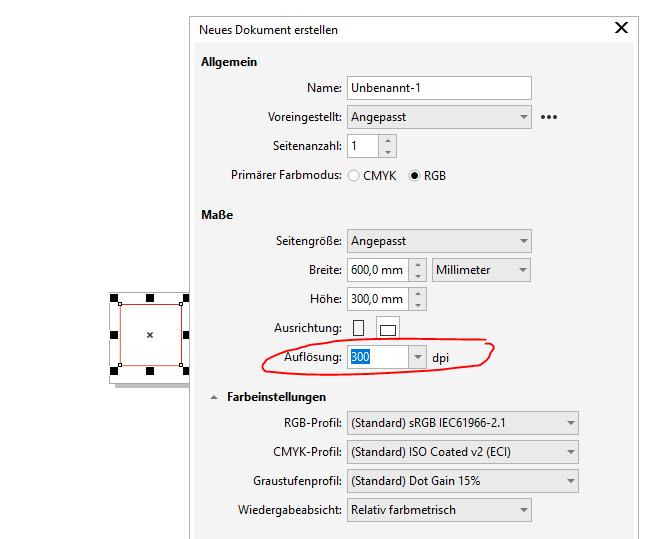
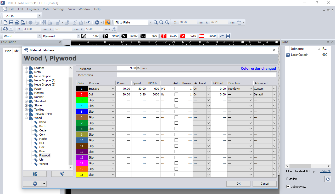
As depicted in the illustration above, the value to be entered in my PPI parameter is 300, because my dpi value on CXorelDraw is 300 (See circled part). However, after trying to change the PPI value to the specified value on CorelDraw (300), I discovered that the least value of the PPI on Trotec JobControl software is 500. SO what I did was to change the dpi value on CorelDraw to 500 dpi.
In addition, I changed the frequency to 1000hz, since I am working on 'Wood'.
Pass parameter
The Pass parameter determines the number of engraving or cutting passes. With some materials, for example, it can be advantageous to engrave with lower power and high speed, and then repeat this process several times. This means that the material is less stressed per pass. For example, this approach is appropriate for a relief engraving.
For this test I set the 'Number of Passes' to 1.
For this test I set the 'Number of Passes' to 1.
Air Assist parameter
During laser engraving and laser cutting, the supply of compressed air can significantly influence and improve results. Furthermore, Air Assist protects the lens from damage, as it stops dust from adhering to it in the first place. However, there are applications in which the Air Assist is deliberately switched off. When engraving TroLase engraving materials, for example, a more attractive engraving result is achieved without Air Assist. In this case, the lens must be checked for contamination more frequently than with Air Assist.
For this test, I set the air assist as 'ON'.
Z-offset parameter
The z-offset describes the focus setting. If the z-offset is set to zero, it works "in focus," meaning the focus is exactly on the material surface. However, there are also applications in which deliberate defocusing is desired. For example, when engraving large areas on TroLase, we recommend defocusing 2mm for a consistent engraving result. The following z-offset values are possible: - 5 mm (table moves up, i.e. closer to the material) up to 127 mm (table moves down, i.e. further away from the material).
Also, for this test I set the value for the 'Z-Offset' to 0.00
Note that cutting and engraving speeds are not comparable. Basically, cutting is slower than engraving. A "high" cutting speed is 10%. if you increase the power value, more energy is introduced into the material, which leads to a darker engraving in wood. The engraving is thus also deeper. The reverse is also true -- reducing the power results in a lighter engraving.
For information on the parameters for Trotec Laser cutting machines, please visit this LINK .
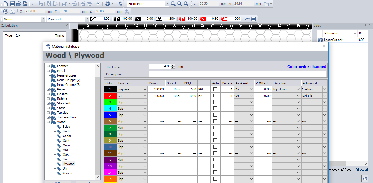
The final parameter set is depicted in this picture. Please be informed that the value changes either incrementally or decrementally.
Test
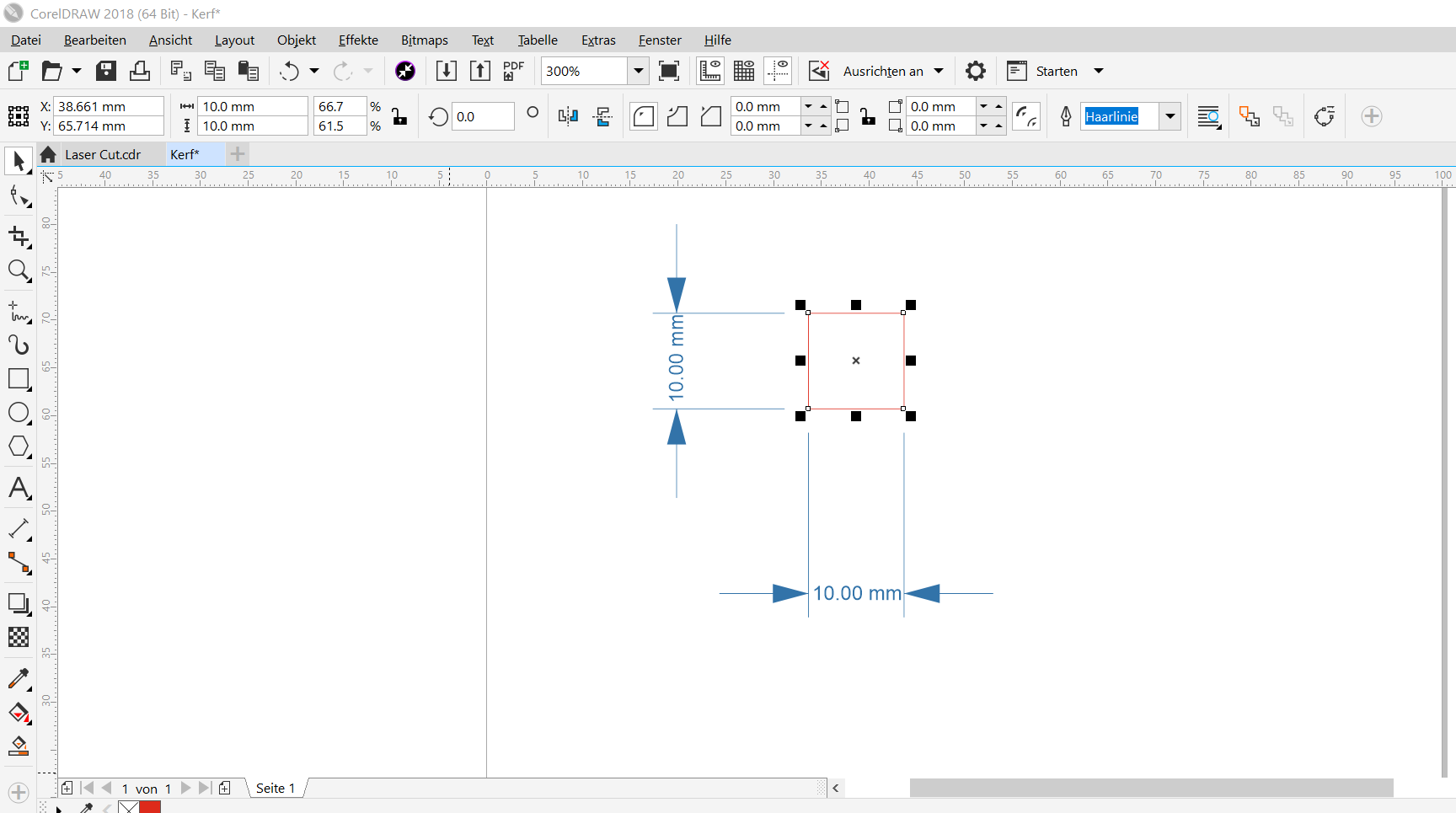
In order to calculate the kerf, I created in CorelDraw a 10 mm square. After that I cut it in a 3mm plywood using Trotec Speedy 100 laser cutter. Please note that I played some gymnastics with the cutting parameters to understand how different parameters (such as speed and power) affect the cutting. Finally, I measured noted the size of the cut square. The variation between the original intended size (10mm) and the cut piece are documented. To calculate the kerf, I used the formula below:
(Size of the square - size of the hole)/2
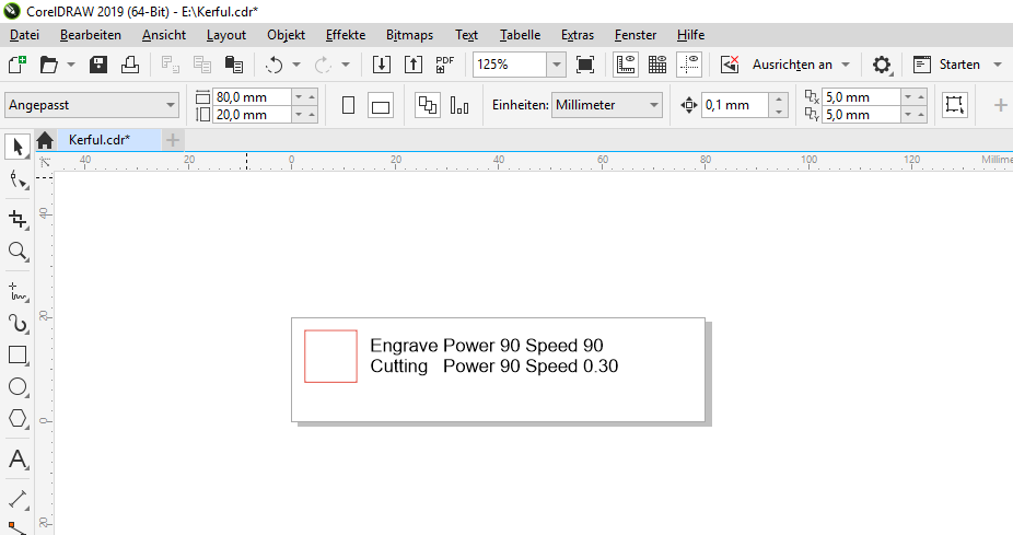
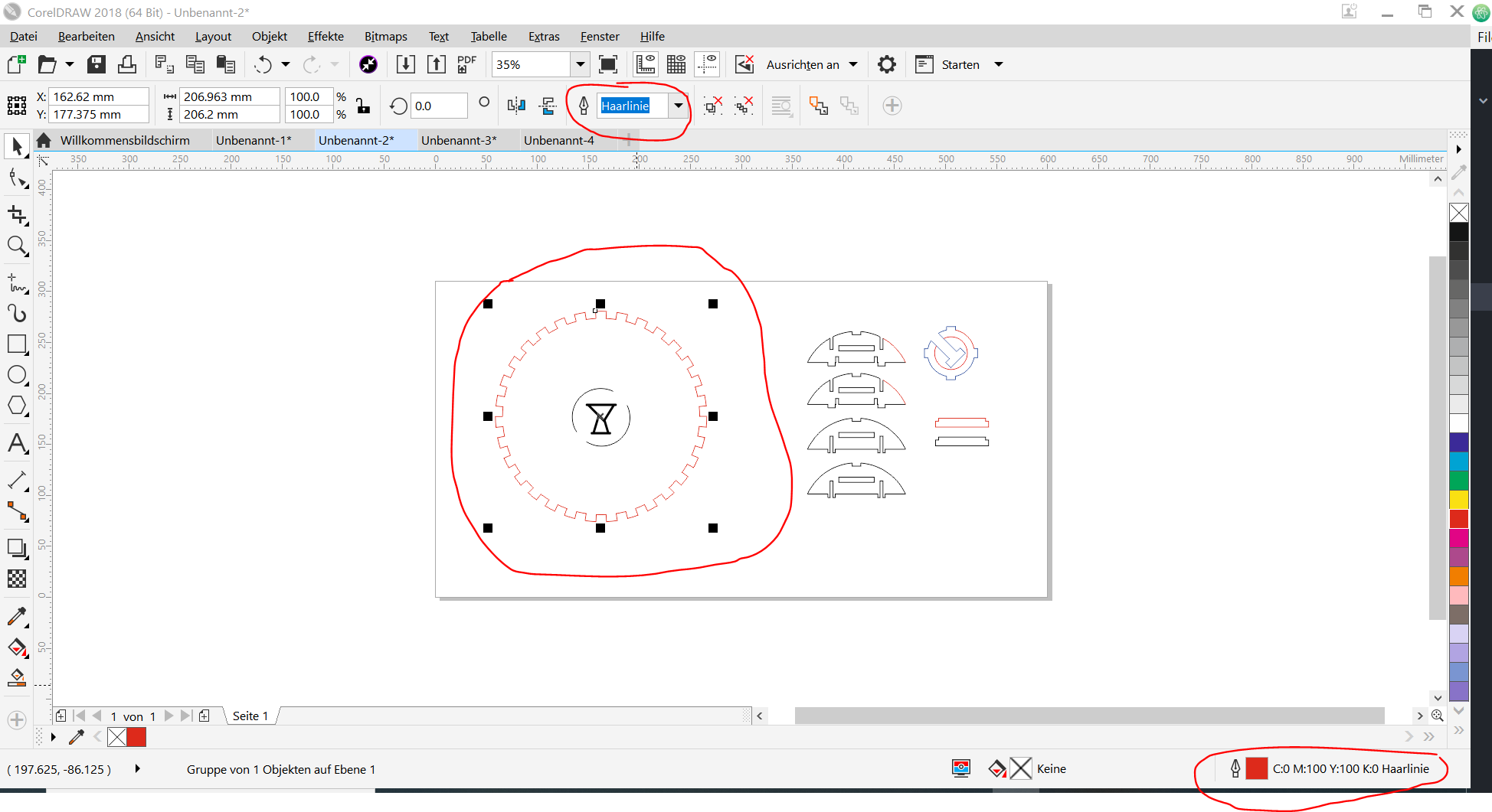
Few things to note is that, I changed the colour of the border to red, because that is the default colour for cutting on our Laser cutter. This can be changed in the settings in case you are allergic to colour red. In addition, I also changed the font size to 'Hairline'. These are the two useful information I can share with you right now.
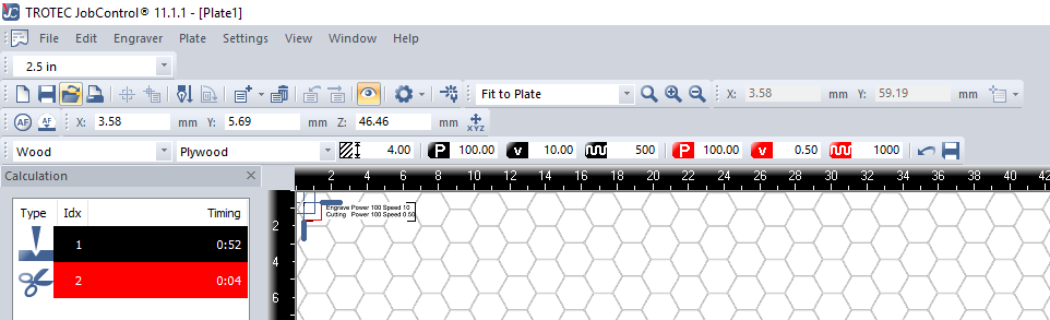
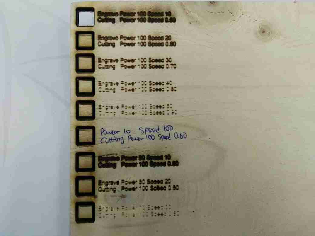
One of the decisions I made was to conduct two different test. Which is to check the effect of the Power on the Speed in an inverted form. That is, for Engraving When Power is 100, then Speed will reduced to 10 (inverted), vice versa.
In addition, for the cutting speed, I discovered that lowest value for the speed is 0.01, while the highest as mentioned above is 10. So, in order to save time, I decided to move in increments of 0.50 till I get to speed value 1.00. Same goes for the cutting process.
Test Result
So after trying different paraments where I fixed the Engraving Power at 100 and alternated the velocity from 10 to 50. I discovered that the faster the velocity of the engraving, the less clearer it becomes. As well as the higher the power the more burnt the job becomes.
With regards to the cutting process, I used four different paramters. These are:
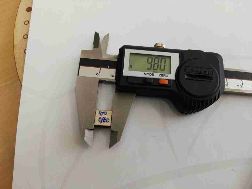
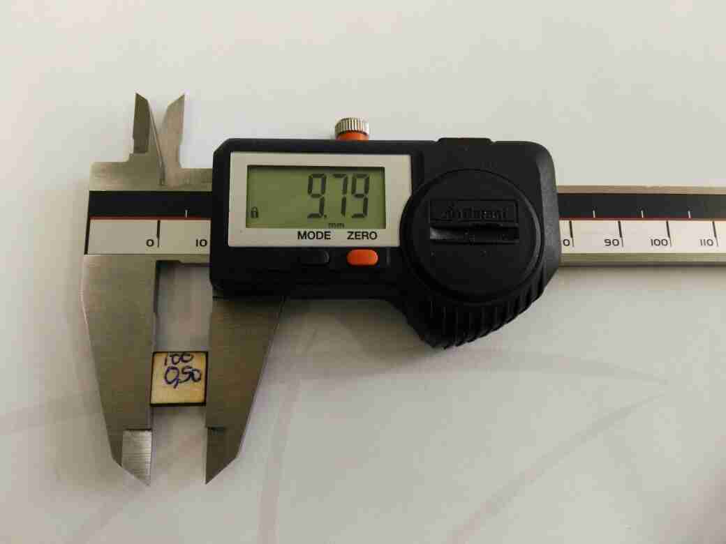
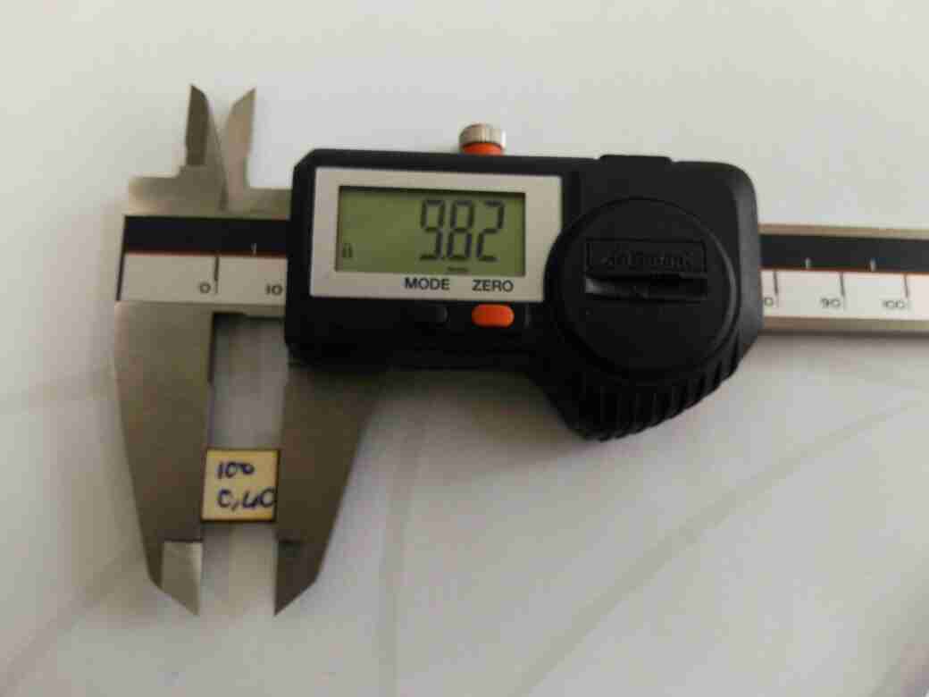
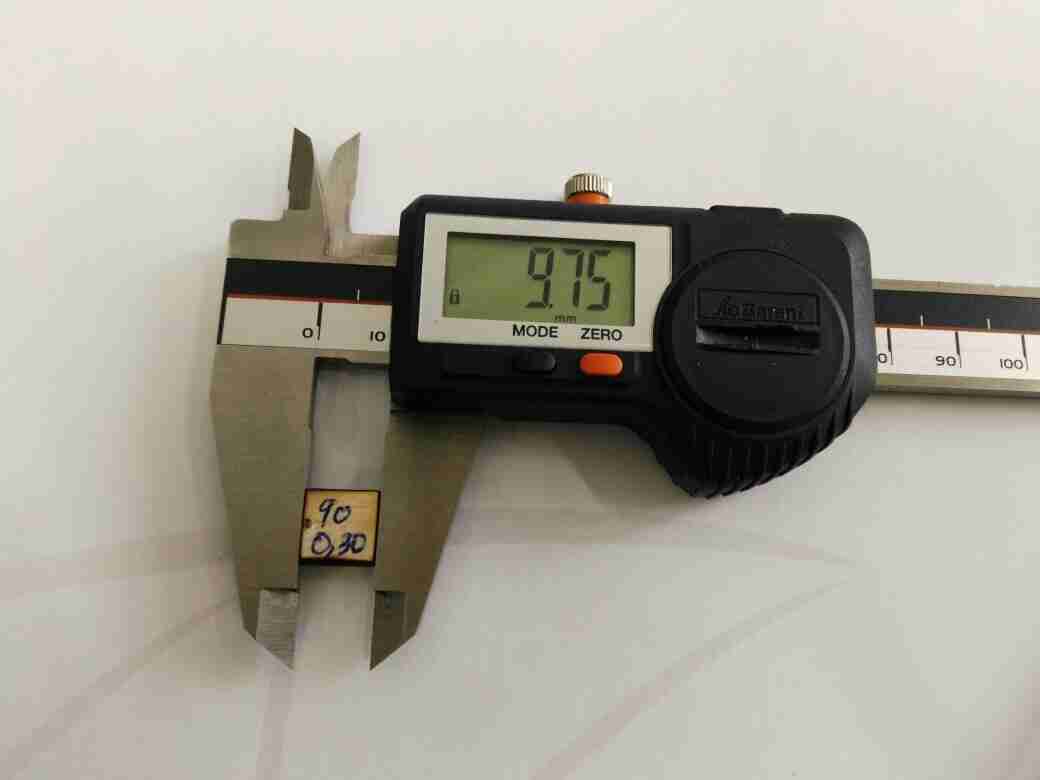
Kerf Calculation
Based on the formula for calculating the Kerf presented above. The Bulleted section below shows the Kerf calculation of the machine:
The pictures below shows their results.
Observation
After making the first test with Speed = 100, Power = 90, I discovered that nothing was showing. So I decided not to proceed with higher speed.
So after doing the first test, it became apparent that something was wrong with the 'Autofocus I thought I had already set as 'On'. So what I did was to use the opportunity to clean the lens and the mirror, and go for another test. Below you will find the result of the new test, now with the autofocus consciously set at all times.
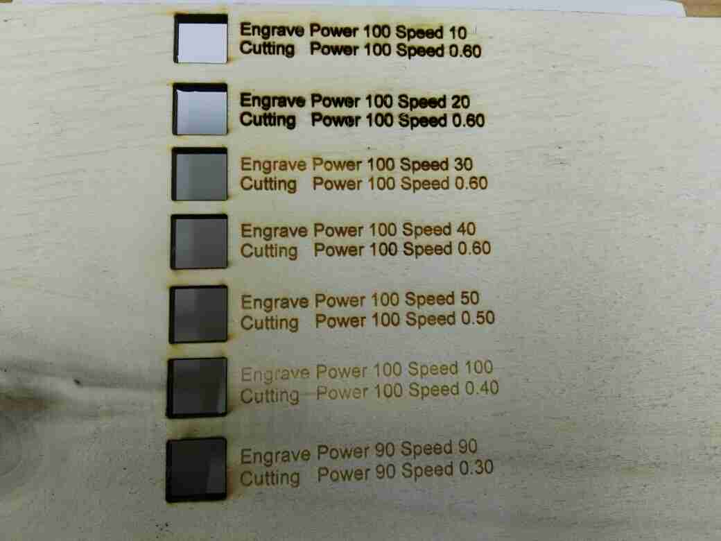
Depending on your preference, I think the best option according to the chart presented in the picture above is the parameter with Power = 100, Speed = 50 or 40. I also think this should still be fine for Power = 100 to 80 with the Speed = 50 or 40.
Individual Assignment
Cut something on Vinyl
To execute this task, I used Corel Draw to make my design. After which I am going to look for an external vendor with a Vinyl Cutter to cut the pattern out.
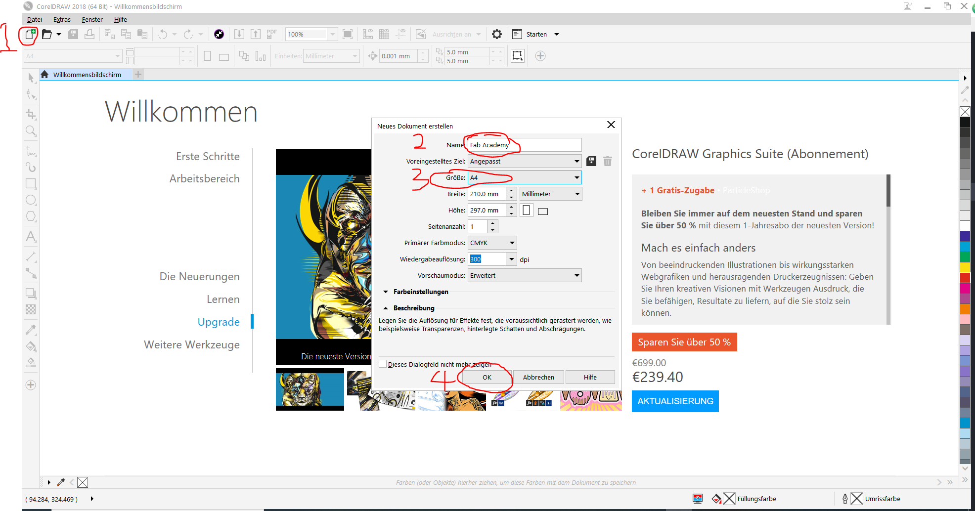
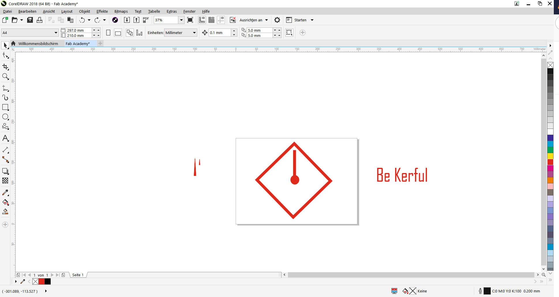
So I launched Corel Draw on my computer, and selcte the new document tab on the 'Menu', Enter the name, Size, and click 'OK' (See picture below).
Then I changed the orientation into 'Landscape'
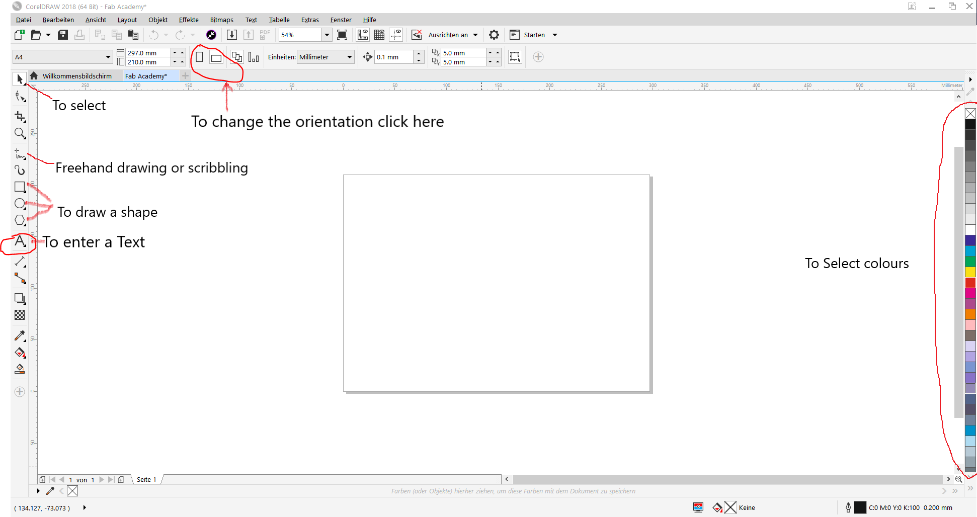
I inserted some shapes to replicate the design in my mind, and also rotated it to the desired angle. Since a picture is better than a thousand words, how about you just follow the pictures below. In case you like the design, please feel free to download it in the download link on the window pane above.
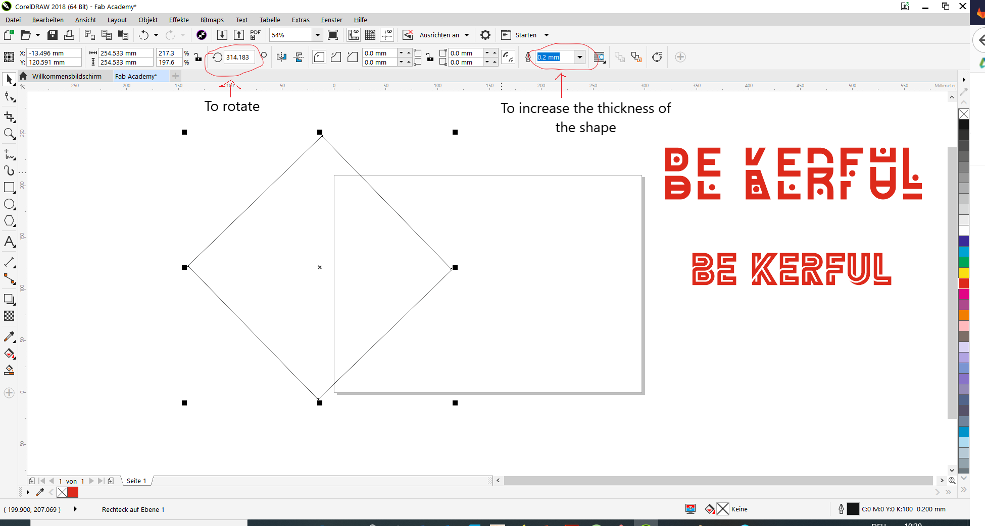
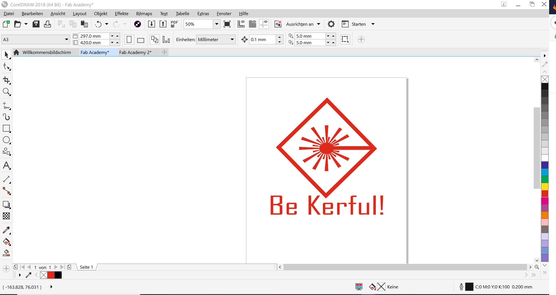
Just as I inserted the shape for the rectangle, I also inserted one cirlce, one rectangle (which I elongated), and lots of triangles which I later inverted to represent the logo of a laser.
After some moments of intense work (just kidding!) I came up with this design.
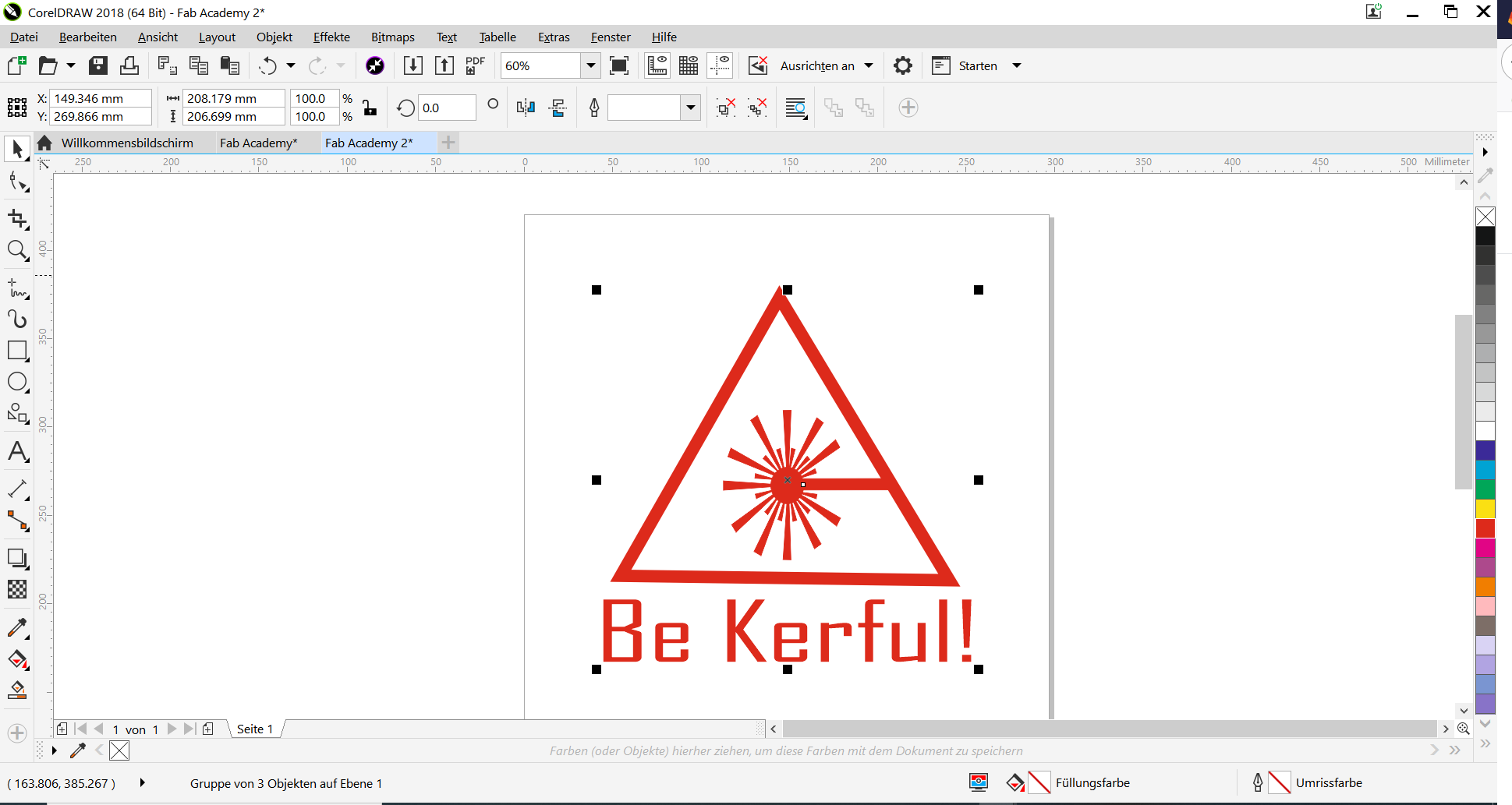
Then I decided to also create another option for those who would like a different kind of 'WARNING'.
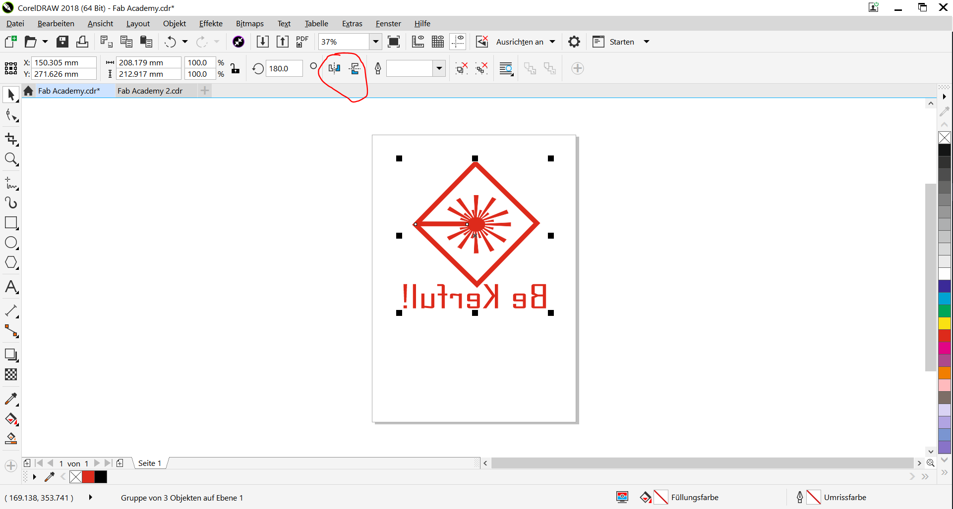
Lest I forget, there is one vital information I forgot to include in my documentation. DO NOT forget to mirror the design before cutting. Unless you want it read upside down, which wouldn't be cool.
I saved the designs in different formats (AI, SVG, CDR, and PDF). So if you would like to download the design please click on Download Files.
As for me, Imma go make some cool T-Shirts with this designs, just to make myself look cool!
Cutting
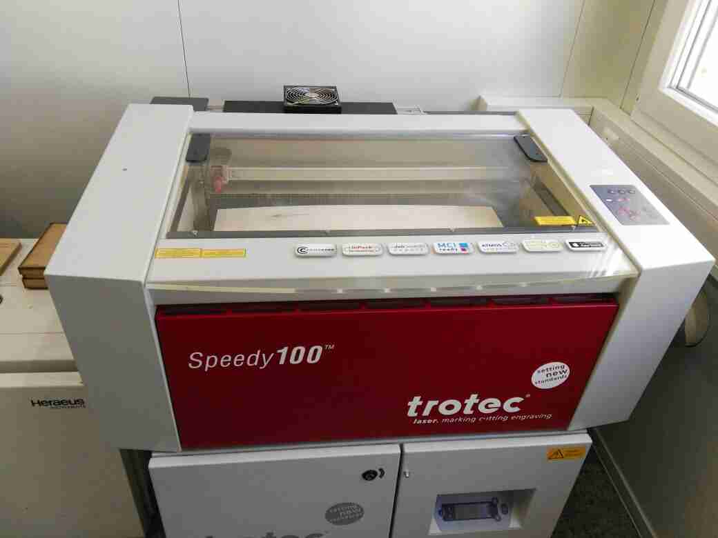
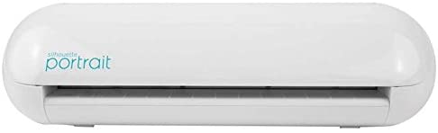
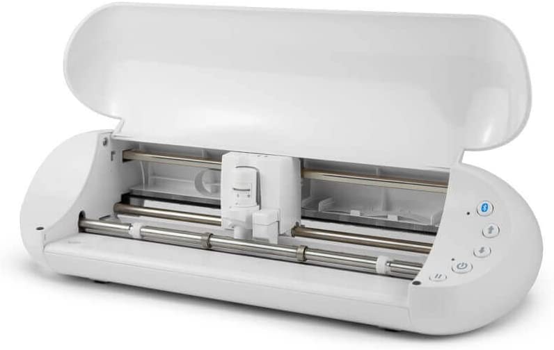
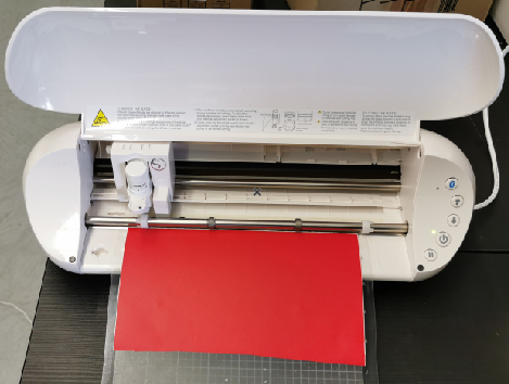
I initially wanted to make a T-Shirt with the design, but I had to resolve for a quick detour and just make something small instead. For this, I will be using the Silhoutte portrait vinyl cutter. You can see the picture of the machine below.
The first thing I did was to install the Silhouette Studio software for the machine. Download the Current version, which is the updated version of the software. Then after download, open the software.
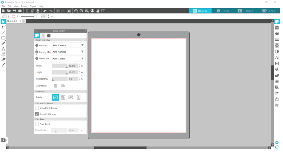
After launching the software, I was taken to the design page of the software package.
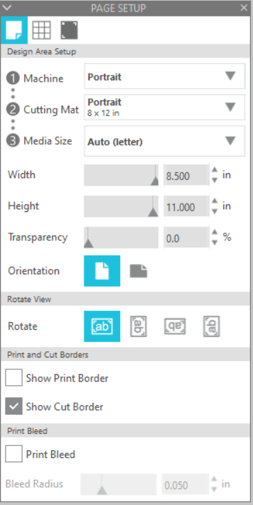
Then I changed the parameters for the job on the setup page of the machine. As depicted in the picture below.
After which I uploaded my design on the design page. At first I attempted to upload the files in pdf, and cdr format. But the machine did not recognize it.

So I then exported the files to PNG. Then I loaded the material to cut on the tray of the vinyl cutter.
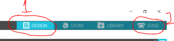
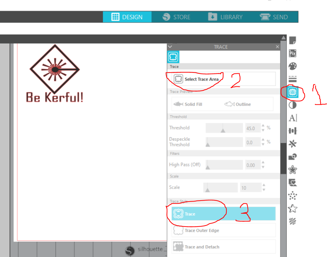
To cut the job, just insert the PNG file, then on the 'Design' menu. Click the icon that represents the trace (Number 1 on the Picture below), click 'Select Trace Area' (Number 2 on the picture below), then click 'Trace' (Number 3 on the picture below).
After all those moves, you should get something like the picture below.
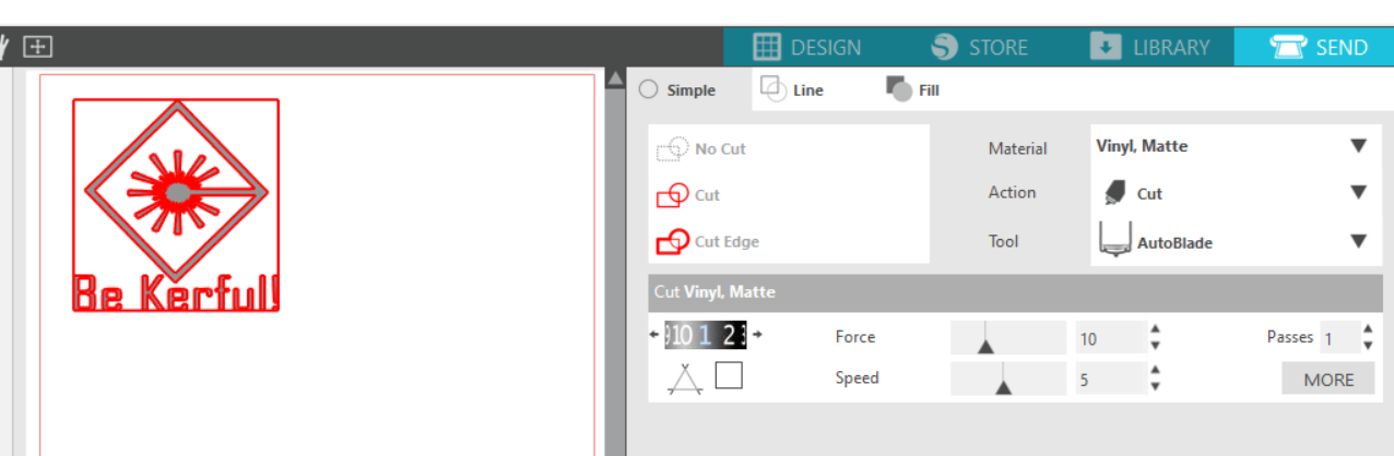
Then simply click the 'Send' button to launch the job.
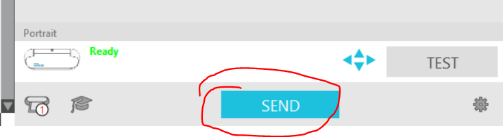
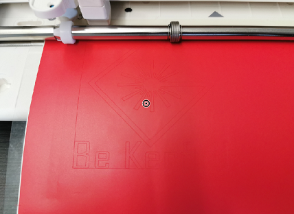
Whoop! Whoop! Just like a magic wand, the vinyl cutter did its magic and produced the coolest warning sign for any Laser workshop! So all I did was to just clean up the cut job and find somewhere to stick the sticker on.
Hero Shots of Vinyl Exercise
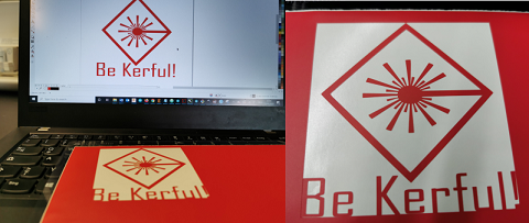
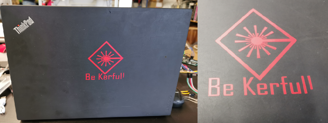
Below, you will find some pictures showing the sticker on my Laptop. One cannot be too Kerful nowadays!
Laser Cutter
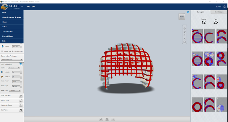
I am just thinking out loud! So consider yourself super human to be able to read my thoughts! This whole parametric design thing would have been way way way way easier if a cheat software was allowed. I could have easily translated the CAD design to parametric using 'Slicer' from Fusion 360. However, I have to go through the eye of the needle to get this done *Sighs*. 'What doesn't kill you will definitely make you stronger'. Let's go CHAMP!
So I am back to getting this done. I will probably start with this. One of the vital things to consider before using the laser cutter is that the 'Outline Width' must be set to 'Hairline'. The cut colour can be changed to whatever suits you, but from my understanding, Red is the default colour. So use red as the colour. In summary, set the outline width to hairline and the color to Red. Whatever shape that does not meet this parameter will simply be engraved instead.
Before proceeding into this, I must indicate that I am in a remote location in Ghana, and I was working offline for this part of the project. Probably not a good time to have gone on holidays, and definitely not a good way to have ones holiday. However, I am determined to be a good FabLab Guru. So I'mnot giving up so easily!
So, one of the first things I did was to set up some parameters on my software. Why did I set that up?
To setup the parameter on Fusion 360, go to 'Modify' then select 'Change Parameter'. Then you should get an option like the one depicted in the picture below.
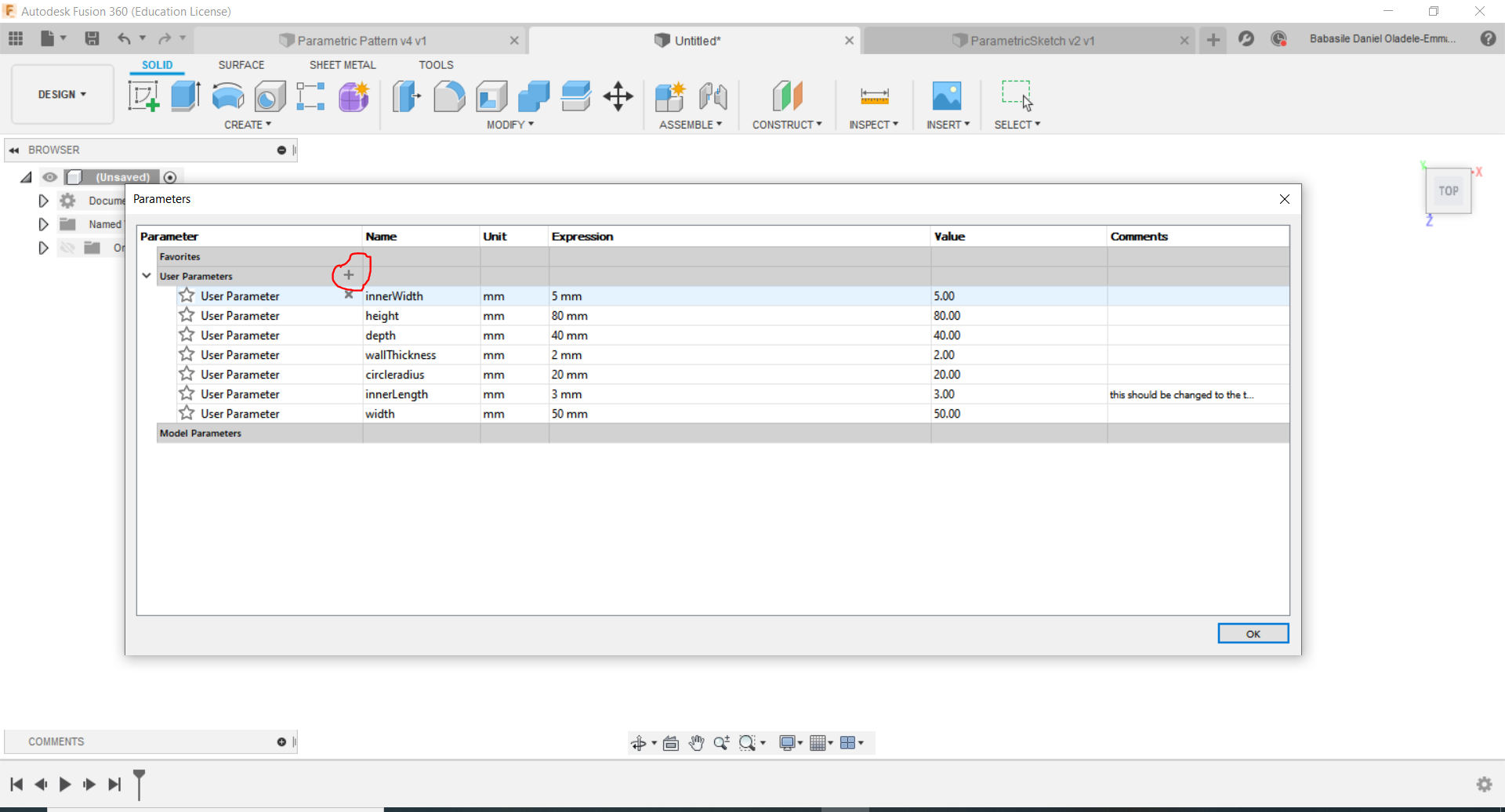
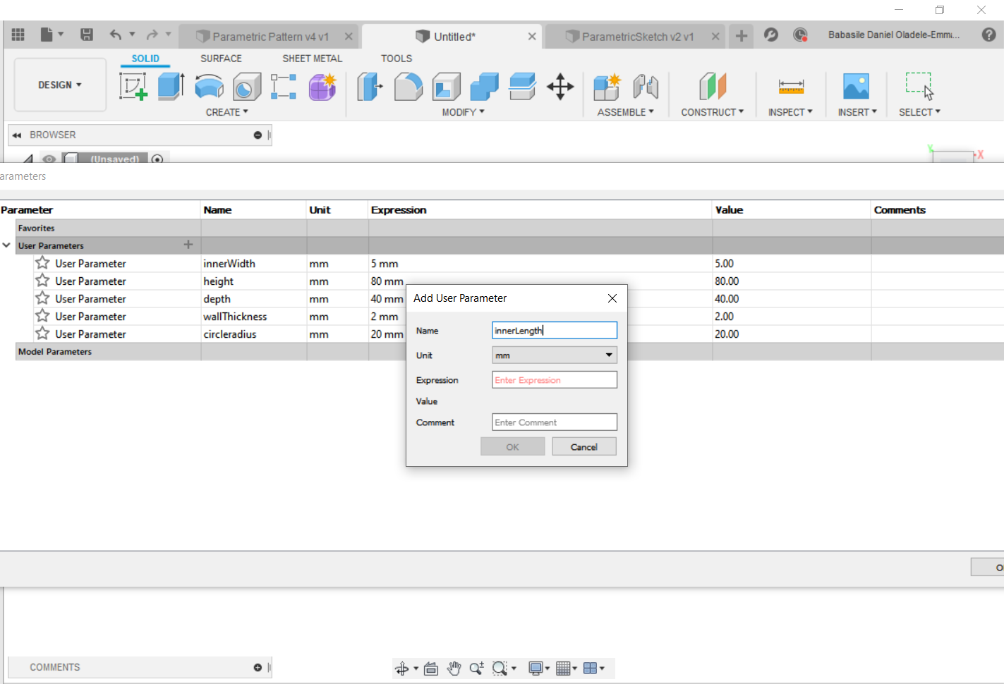
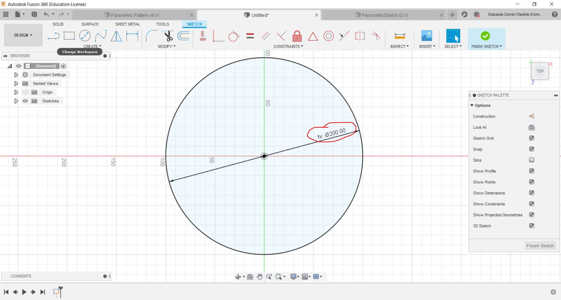
After setting up your desired parameters, then you can easily call this parameters by typing the names. One of the benefits of setting up the parameters is so as to allow simplicity and uniformity with the design jobs. What I mean by uniformity is that, any changes made on the 'Change Parameter' function is automatically implemented on the design jobs. Another benefit is that you could perform simple arithmetic functions on the parameters. For example, when drawing a circle, since I have inserted the radius of the circle to be 20mm, I could simply type circleradius * 10. Which will give me a circle with 200mm diameter (See the picture below). You could also call other parameters you already created as the value in the new parameter. I suggest you play with the 'Change Parameter' option. There is no harm in trying.
Now that the parameters has been set, we can proceed with the task.
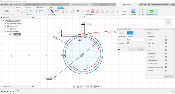
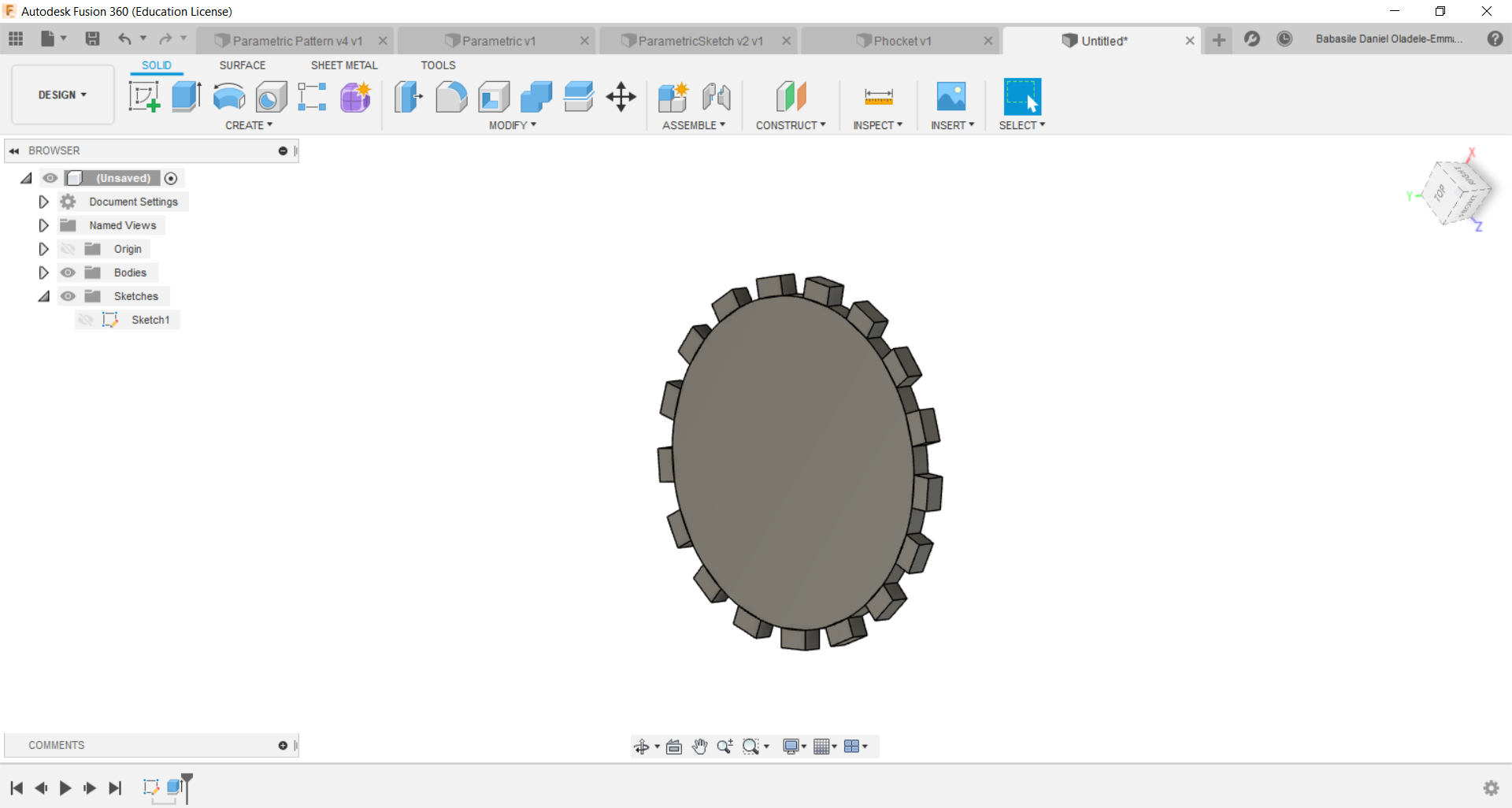
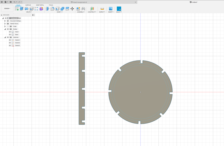
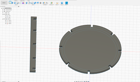
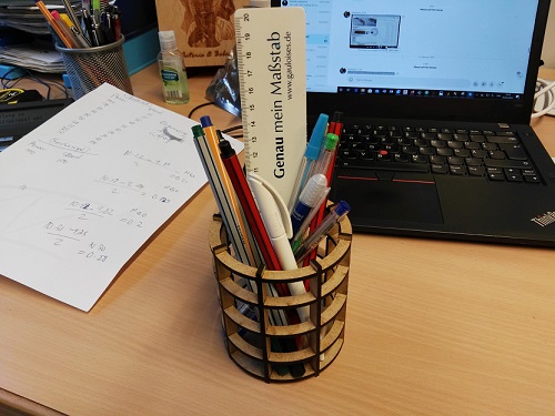
For the laser cutting assignment, I planned to make a parametric circlar pen holder.So what I did was to set some parameters for the design on Fusion 360. Then I drew the design, after which I used one of the good functions on Fusion 360 - 'Circular Pattern', which can be found under 'Create' menu, 'Pattern', then select 'Circular Pattern' (See the picture below).
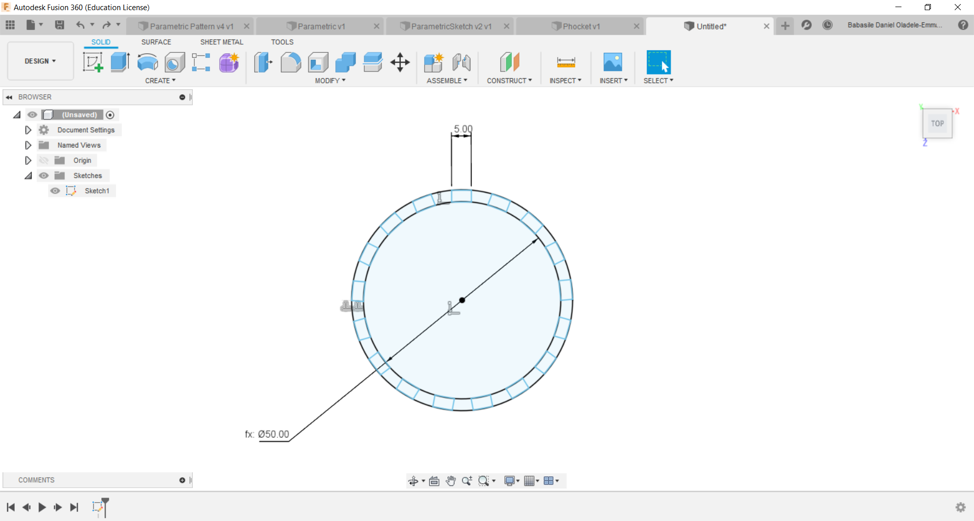
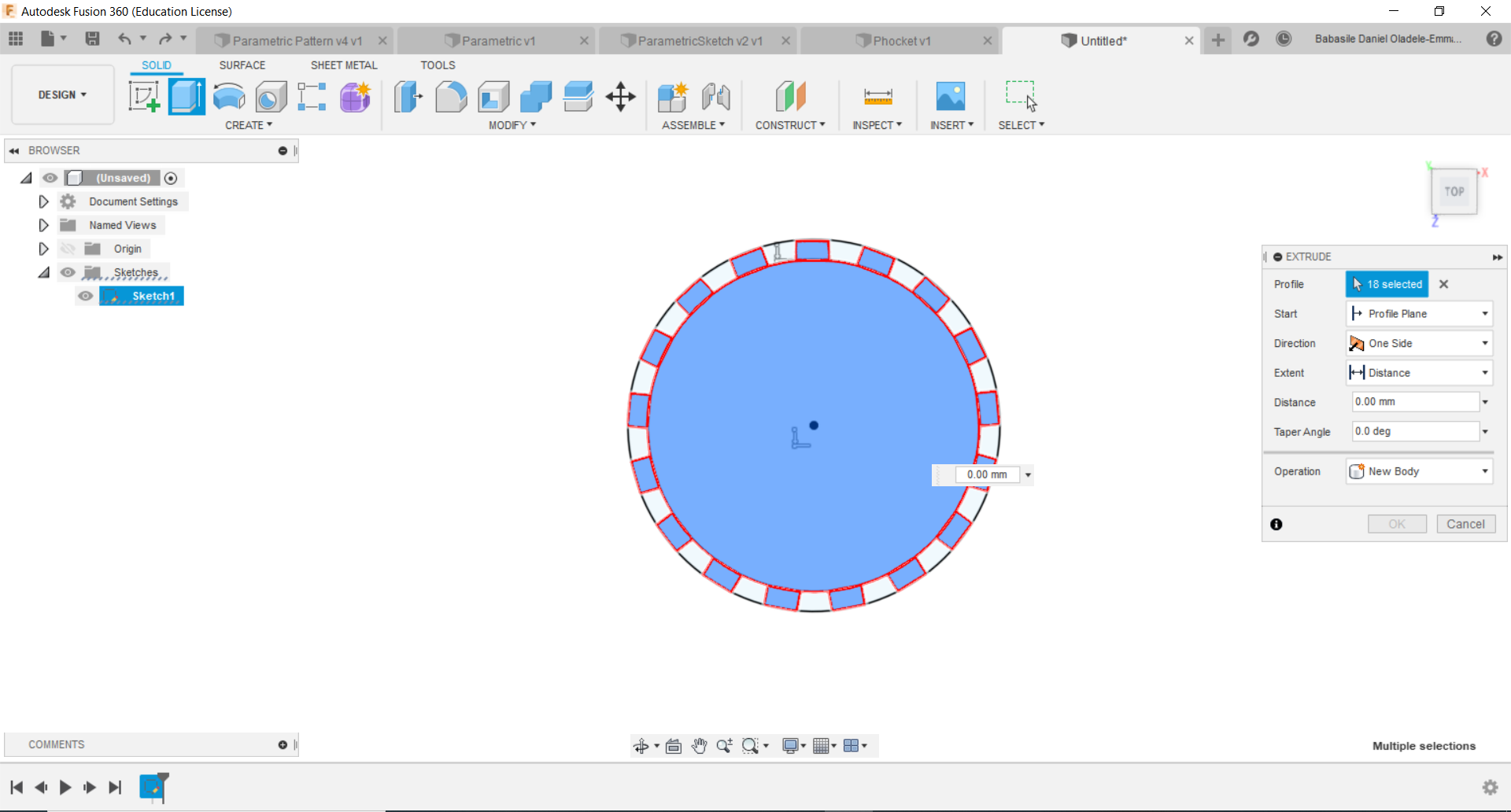
Once you are done doing that you should have a structure as depicted below. However, I must confess that the bottom space between the circular pattern is 4.15mm, while the upper space is 5.32mm. However, I do not have a vivid understanding how to solve that issue, and I am not anywhere near a laser cutter to see how effective it is. Afterwhich, I extruded the shape.
Now I will attempted to make the connector for the base created. Honestly, I had to go back to junior secondary school to do this. Since I wanted to create the fram for the 'PenHolder' I had to know the circumference of the circle (with a radius = 25mm). Therefore, I used the basic formular 2*pi*r. Which gives 157.10mm. With this, I am sure to create a frame that will revolve round the whole diameter of the PenHolder's frame.
In addition, I tried to learn more about how to make a living hinge. Upon my discovery, I discovered this website from which you can download different versions. I believe this might be of assistance later to those who need it.
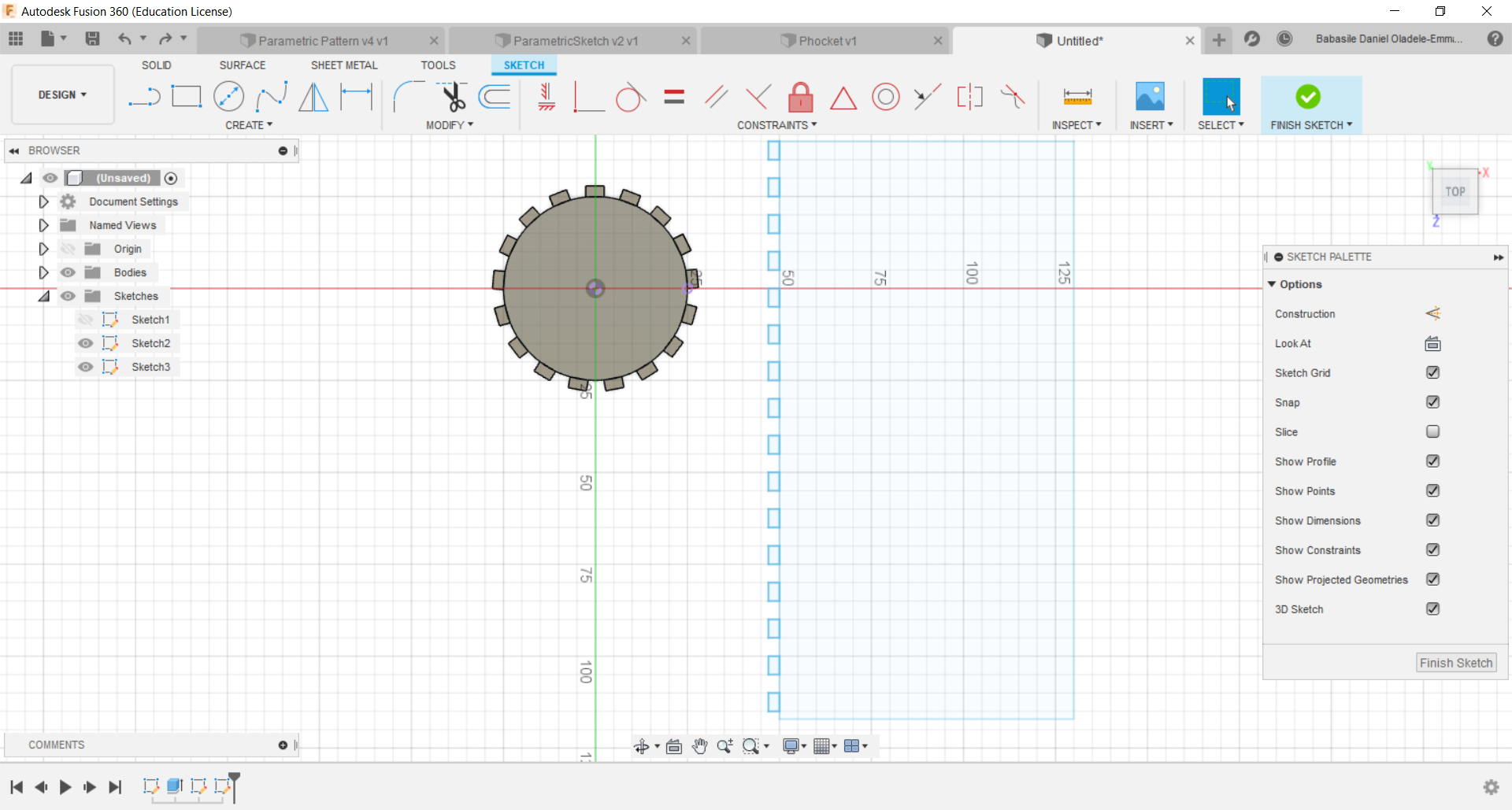
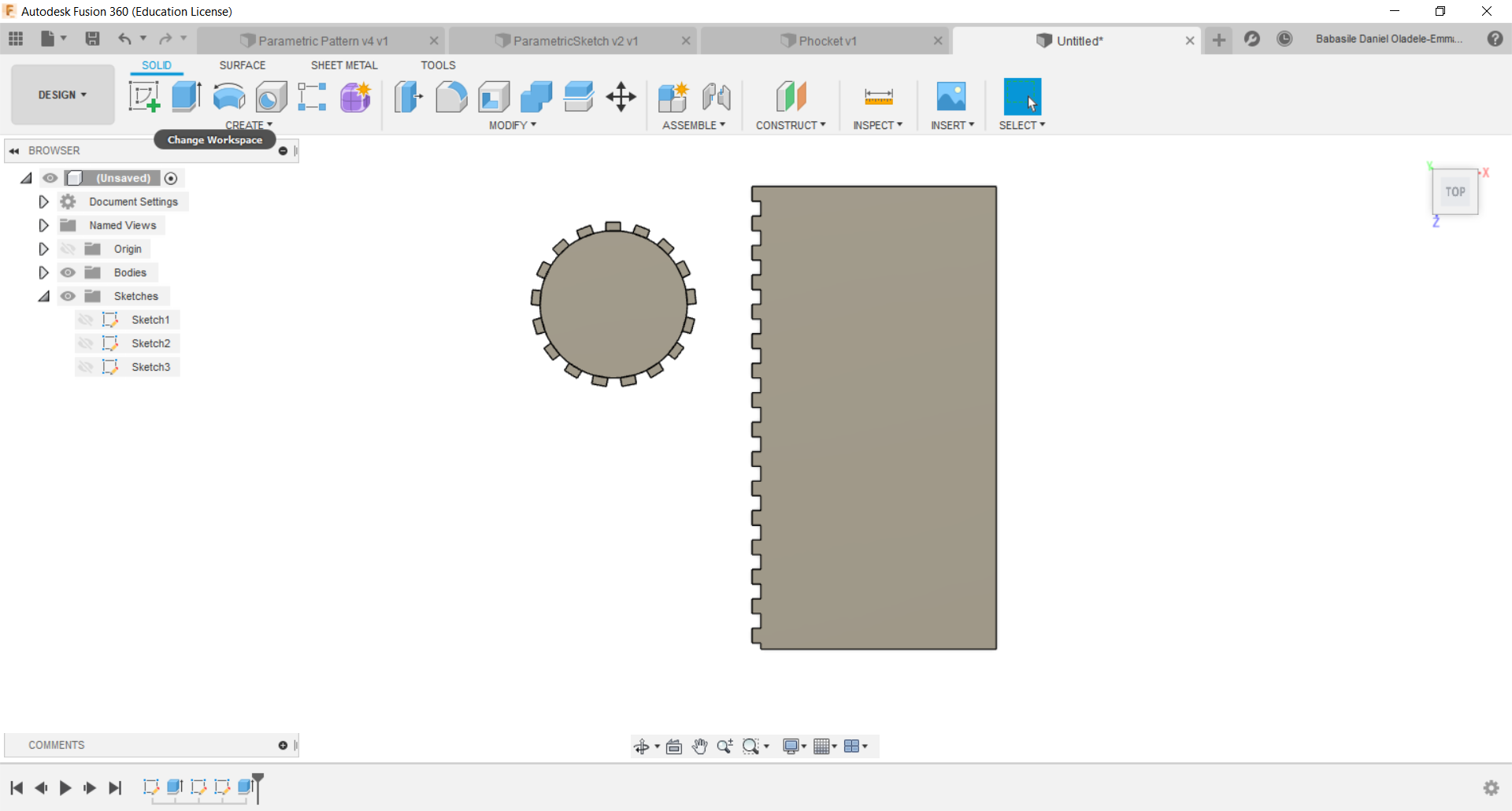
So what is now left for me is to practice what I preach, and to do that I have to include the living hinge on the design. So I can create a design flexible enough to be bent round the base. Before creating the living hinge, I got good at parametrising. So what I did was to insert the parameters for the hinges, which based on my study of the living hinges, I noticed has a long length and a short one. Then I inserted the lines on the designs ready to be shipped to the 'Point of no return'. Below you will find the picture depicting the journey so far and files to download.
New File
After surviving a great expedition to West Africa, I decided to carry on where I stopped. Not satisfied with the initial design I made (due to silly flaws in the design), I decided to make another design, and I also decided not to delete the old designs. This decision was for learning purposes. Below you will find the new information about the new design.
Before proceeding, I must confess that learning about parametrising is a good thing. It really makes your life easy, because you do not need to make modifications all over the designs. All you need to do is to just edit the poarameter, and it will automatically updated on the designs. Below you will find the illustrations depicting the new parameter I used for the new design.
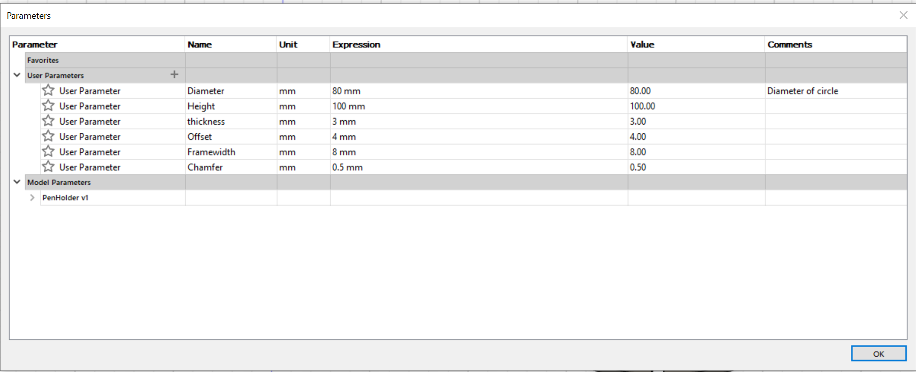
The new designs follows below:
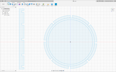
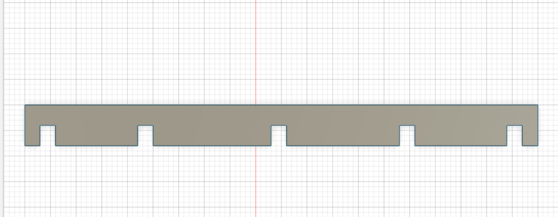
Whatever you do, Do not forget to use CHAMFER! So as a faithful steward, I have inserted the chamfer. According to the lessons from Neil, the chamfer makes it easy for the attachments to be made.
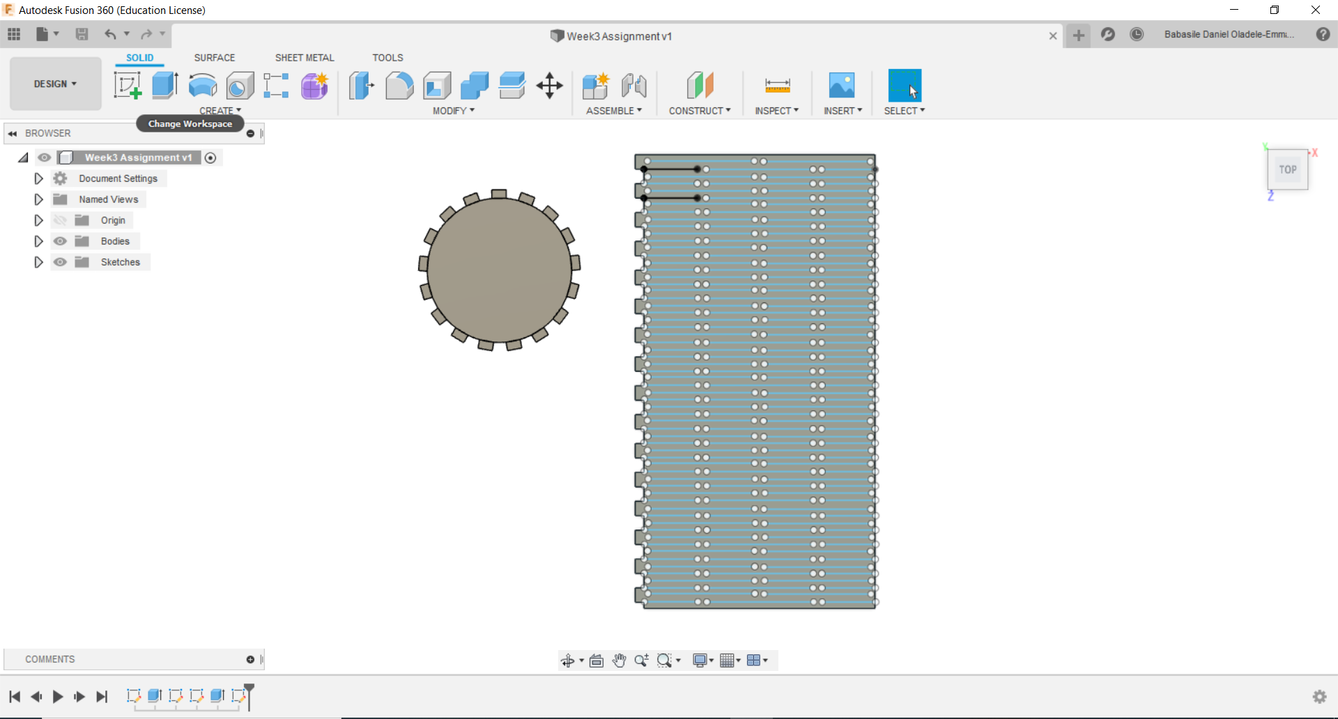
After this, all I simply did was to make little modifications, copy and paste the designs.
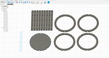
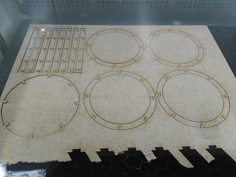
The Illustrations below shows the process I went through to cut the material.
Assembling of the Parametric Pen Holder
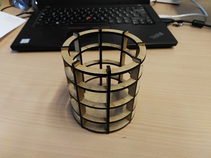
Pen Holder in use.
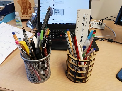
Just to make myself feel good, I compared the Parametric pen Holder I made to the one I bought from the EuroShop here in Hamburg. I must confess, I am really impressed with my project. Without doubt, Fab Academy is a good investment, both in time, financial, mental, psychological, and resources.
I saved the designs in different formats (cdr, f3d, dwg and dxf). So if you would like to download the design please click on Download Files.