Group Assignment 04: Computer-Controlled Cutting
Characterize your lasercutter’s focus, power, speed, rate, kerf, and joint clearance
Fab Lab Kamp-Lintfort
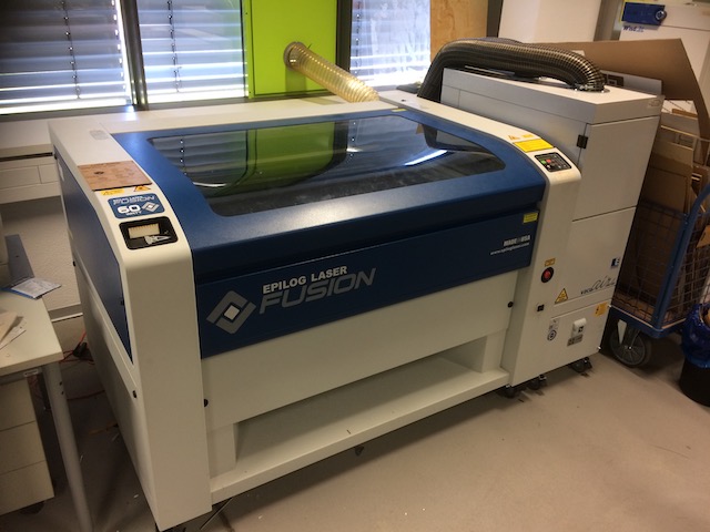
In the group assignment we have to get to know the Lasercutter in the Fablab Kamp-Lintfort, which is an Epilog Fusion.
We have to get started by testing and playing around with the different settings for the machine.
Standard Operating Procedure
The standard operating procedure for this machine is as follows:
- Open the lid and remove any large “swarf” from the bed - think fire hazard.
- Place the material to be cut squarely against the edges. Check it’s level in the bed. Use masking tape if necessary to tack it down.
- Turn on the laser cutter (switch below the emergency stop button).
- Select “focus” from the menu pad.
- Drive the bed down and away from the lens.
- Place the aluminum hanger on its studs.
- Drive the bed up until it just touches the hanger (watch for it to stop swinging).
- Centre the joystick and push it in to set the focal length. Remove the aluminum hanger.
- Select “jog” from the menu and turn on the spotter laser.
- Drive the head to the desired top-left position on the material.
- Push in the joystick to set the zero.
- Turn on the vacuum pump (button low down to the right).
- Set the menu to “job”. The machine is ready for computer input.
Setting the Focus
The Epilog has a simple tool for setting the focus. It’s a triangular piece of aluminum which hangs from a bracket on the front side of the laser. To set the focus, one hangs the triangle, then jogs the laser head down toward the sample until the triangle just lifts off the bracket. It’s pretty obvious when that happens. Then one sets the zero position on the control panel.
We played around a bit with bad focus - the result is just a wider circle with diffuse edges.
Determining the Kerf
In the Epilog Laser Manual we can read about recommended settings for each material and thickness. In addition to a detailed documentary on lately done cuts and their settings is available in the FabLab.
To make sure the joints we cut are fitting perfectly, we have to do differently cut joints and try to find out about the KERF of the laser. The kerf describes the amount of material that is subtracted during the cutting process.
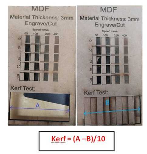
For a material with a thickness of 3mm, we want to try out the following:
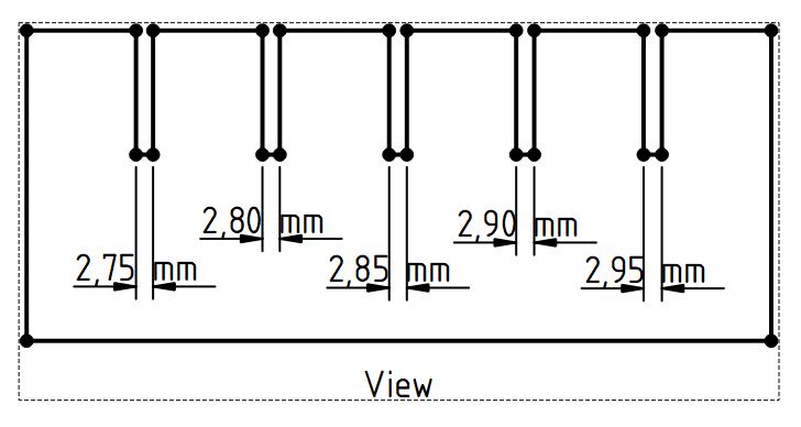
The width of the joint we cut differs in steps of 0.05mm, therefore we can test how the different sizes fit together.
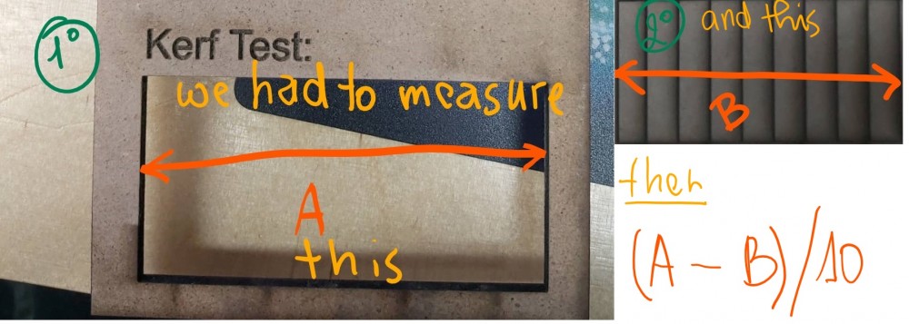
Another good tool to use when trying to find out the kerf of a laser, is to for example, take a piece of plywood with 100 mm length. Then we go ahead and cut for example 10 lines orthogonal to the length of the material.
Afterwards we measure the “new length” of the material. so if we have a 100mm, cut 10 times and afterwards have a length of 99mm, we have a kerf of (100 - 99)/10 = 0.1mm. (Just an example!)
The outcome looks like this:
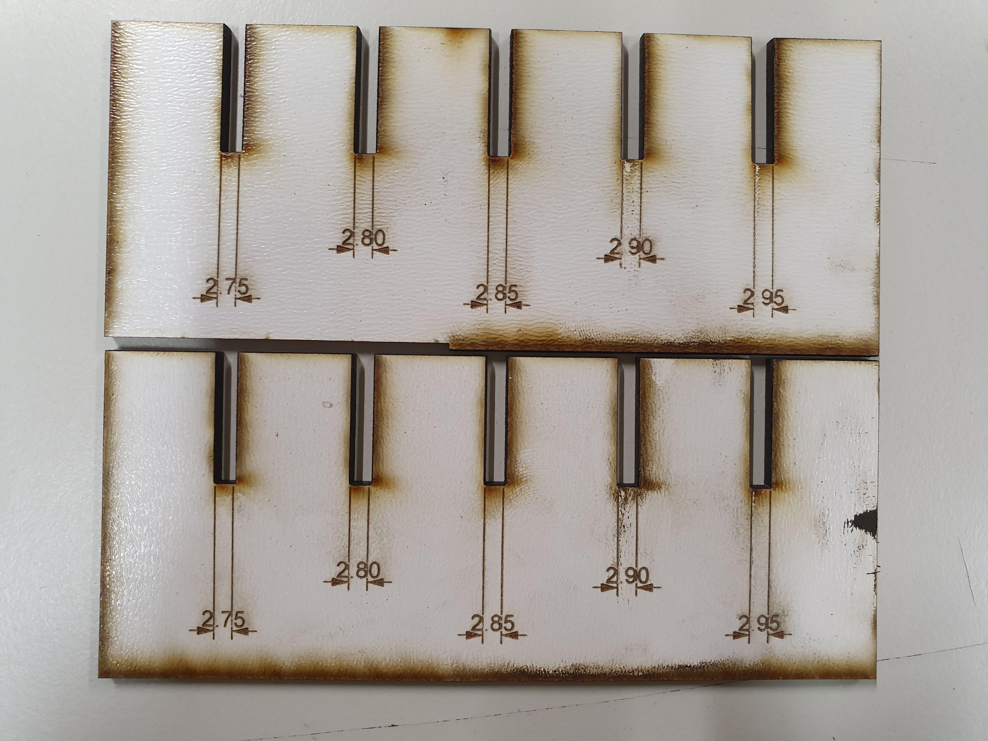
Now we could try the different sizes of joints at put them together testwise. Doing that we found out that a material with a thickness of 3mm holds best together with a joint of 2.9 to 2.95mm.
Depending on how much we want the outcome to be able to be disassembled or not, we can vary these values.
Making a testing piece
We were tasked to work as a group to conduct some tests on the cutting settings, and slot dimensions of the laser cutter. To be specific we were asked to characterize the lasercutter’s focus, power, speed, rate, kerf, and joint clearance.
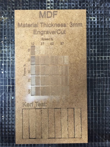
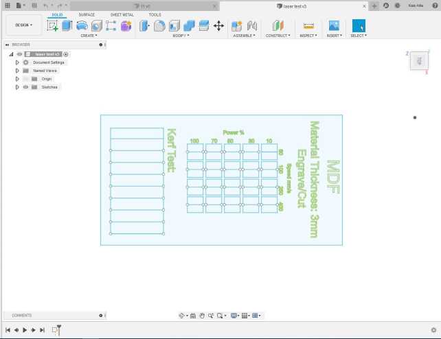
We started with a pattern from our partner lab ENIT in Tunisia (described below):
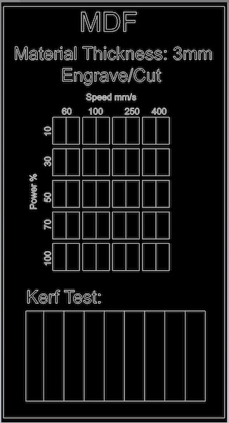
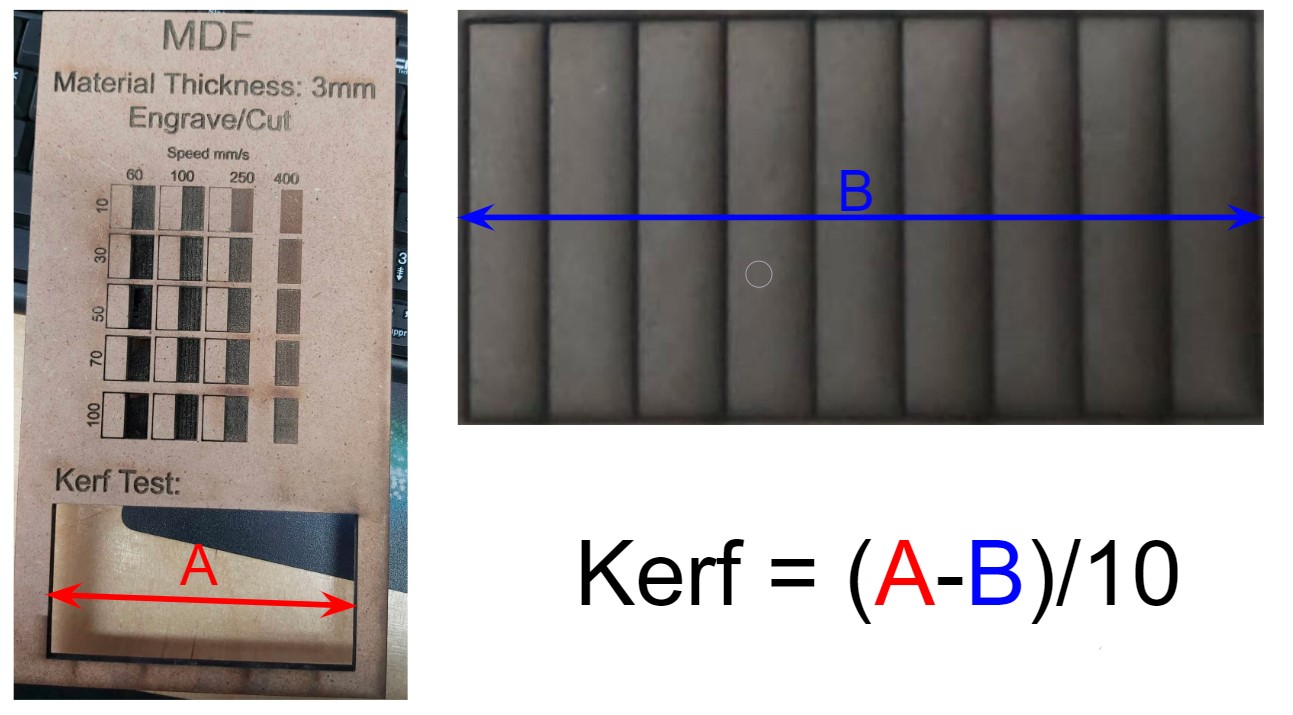
The pattern consists of a matrix of etched boxes arranged on two axes, power and speed. Then at the bottom of the image is a box with parallel cuts which will make a set of rectangular parts, which when extracted from the cutout and put back together, will allow us to measure the kerf (more on that below).
Then we imported the file into Rhino 5 and processed it according to the local instructions. That involved first selecting everything and “exploding” all of the shapes. Then we “joined” the segments back into individual objects (letters, boxes, etc). The next step was to put the various elements all on their own layers so that the laser cutter parameters could be set specifically for each.
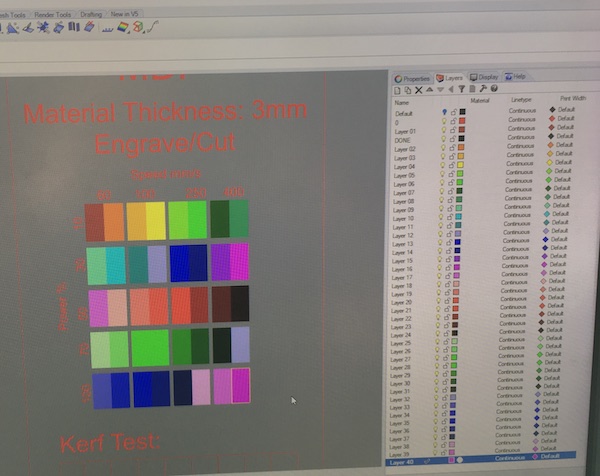
Each of the layers was assigned a specific colour, and the RGB code for each colour was recorded in an excel spreadsheet. These colours were then used in the “color mapping” option in the “print” interface to set the burn parameters for the laser.
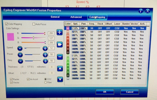
We loaded, focused and jogged the laser as described above, then sent it the print job. We had to do the print in three parts, as the maximum number of color maps per print was 16. The etching was done first, followed by the cutout of the kerf test pattern, and finally of the outer frame. For the etching, the settings were as shown in the color map picture above. For the cutting, we followed the advice of the local instructors and slowed the laser down to 5% with full power and a pulse frequency of 10Hz. We had to do the cuts four times, and at increasing frequencies up to 50Hz in order to finally cut through the 6mm (not 3mm) piece of MDF. The result is shown in the photo below.
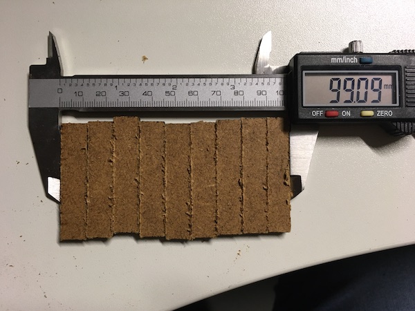
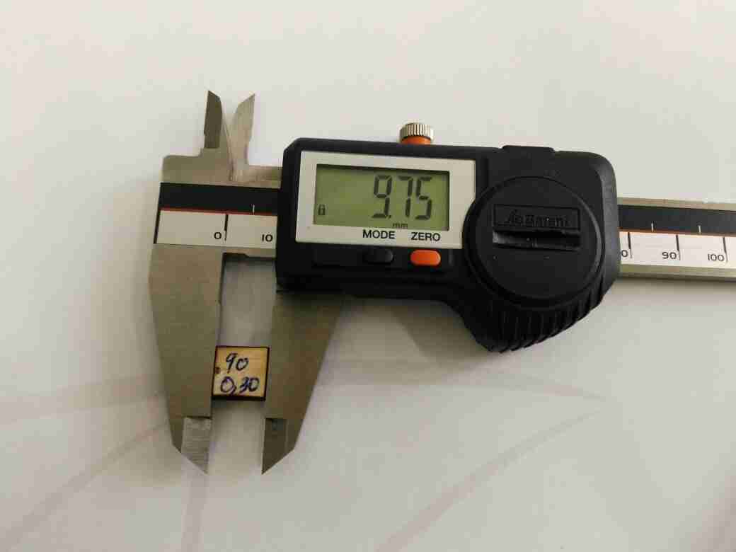
To measure the kerf, we popped out the rectangular slivers, then pieced them all back together and measured the full length with a caliper. The original length of the pattern was 100mm. The reassembled length (shown below) was 99.09mm, after 8 cuts. The kerf was therefore (100-99.09)/8 = 0.114mm.
Software
The software we used for this phase of the project are:
- Fusion 360
- Corel Draw
- Rhino 5.0
Fab Lab ENIT
Small Laser Cutter
As a reminder, kerf is the groove or slit created when the laser cuts any material. When the laser cuts some part of the material desintegrates somehow (e.g. transforming it into powder). This makes the pieces are a little bit smaller than the original design.
Power and speed parameters
The power and speed laser parameters are the most important settings in the material database. They can be set as a percentage between 0 and 100%. Adequate information can be found on this website
- The Power laser parameter describes the output power of the laser. 100% is maximum power. For dark wood engravings or stamp engravings, you generally need high power, whereas low values are used for materials such as paper.
- The Speed laser parameter describes the movement of the laser head. Fast speeds lead to short exposure times, slow speeds lead to long exposure times. For example, large-scale engravings of TroLase materials are engraved at high speeds between 80 and 100%, but for photo engravings with lots of detail on wood, the speed should not exceed 10%. This setting also affects the quality of the laser cut.
PPI and Hz parameters
The PPI parameter (=pulses per inch) determines how many laser pulses per inch are used for the engraving. To achieve a good result, this should be the same or a multiple of the dpi selected in the print setting. If you set this parameter to “Auto,” JobControl automatically determines the optimal resolution of the laser pulses.
During the cutting process, the Frequency parameter is decisive and is given in Hz (=Hertz). It specifies the number of laser pulses per second. For a CO2 laser, the value can be set within a range of 1,000 to 60,000 Hz. For example, if you want to achieve a smooth edge when cutting acrylic, you need higher temperatures and thus this value is set to at least 5,000 to 20,000 Hz. On the other hand, when cutting wood a low frequency of 1000 Hz is necessary in order to achieve, for example, the brightest possible cutting edge.
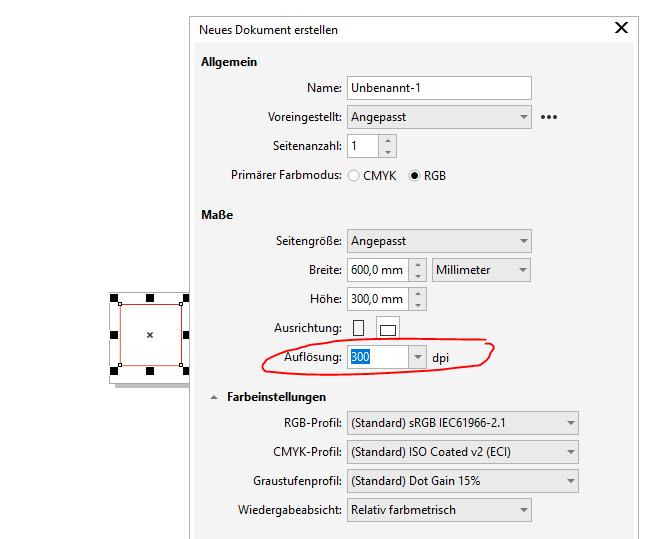
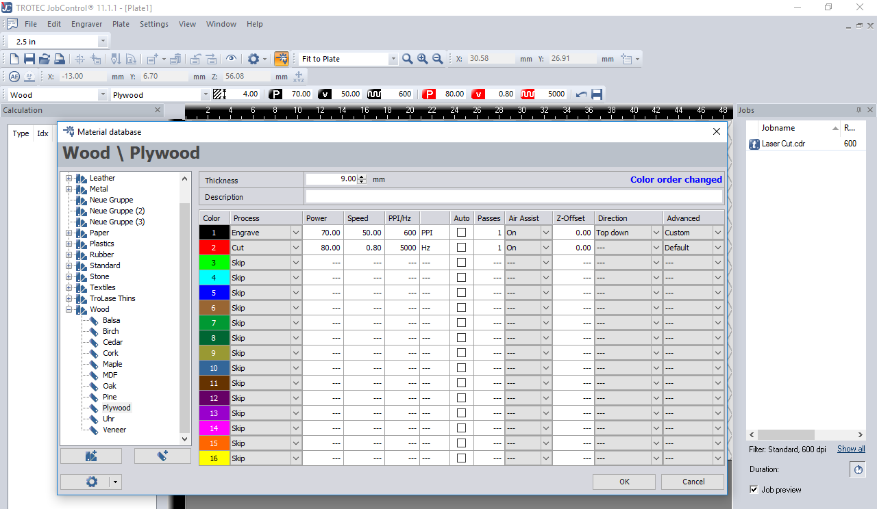
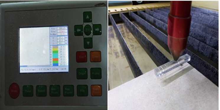
As depicted in the illustration above, the value to be entered in my PPI parameter is 300, because my dpi value on CXorelDraw is 300 (See circled part). However, after trying to change the PPI value to the specified value on CorelDraw (300), I discovered that the least value of the PPI on Trotec JobControl software is 500. So what I did was to change the dpi value on CorelDraw to 500 dpi.
In addition, I changed the frequency to 1000hz, since I am working on ‘Wood’.
Pass parameter
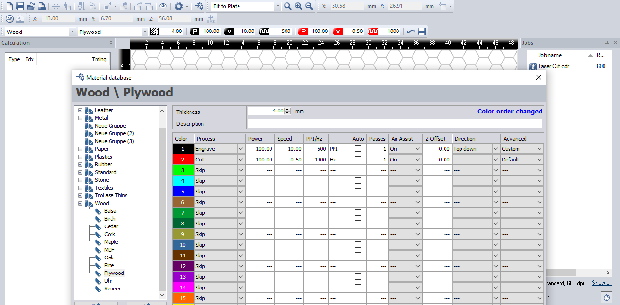
The Pass parameter determines the number of engraving or cutting passes. With some materials, for example, it can be advantageous to engrave with lower power and high speed, and then repeat this process several times. This means that the material is less stressed per pass. For example, this approach is appropriate for a relief engraving.
For this test I set the ‘Number of Passes’ to 1.
Air Assist parameter
During laser engraving and laser cutting, the supply of compressed air can significantly influence and improve results. Furthermore, Air Assist protects the lens from damage, as it stops dust from adhering to it in the first place. However, there are applications in which the Air Assist is deliberately switched off. When engraving TroLase engraving materials, for example, a more attractive engraving result is achieved without Air Assist. In this case, the lens must be checked for contamination more frequently than with Air Assist.
For this test, I set the air assist as ‘ON’
Z-offset parameter
The z-offset describes the focus setting. If the z-offset is set to zero, it works “in focus,” meaning the focus is exactly on the material surface. However, there are also applications in which deliberate defocusing is desired. For example, when engraving large areas on TroLase, we recommend defocusing 2mm for a consistent engraving result. The following z-offset values are possible: - 5 mm (table moves up, i.e. closer to the material) up to 127 mm (table moves down, i.e. further away from the material).
Also, for this test I set the value for the ‘Z-Offset’ to 0.00
Note that cutting and engraving speeds are not comparable. Basically, cutting is slower than engraving. A “high” cutting speed is 10%. if you increase the power value, more energy is introduced into the material, which leads to a darker engraving in wood. The engraving is thus also deeper. The reverse is also true – reducing the power results in a lighter engraving.
For information on the parameters for Trotec Laser cutting machines, please visit this LINK
The final parameter set is depicted in this picture. Please be informed that the value changes either incrementally or decrementally.
Test
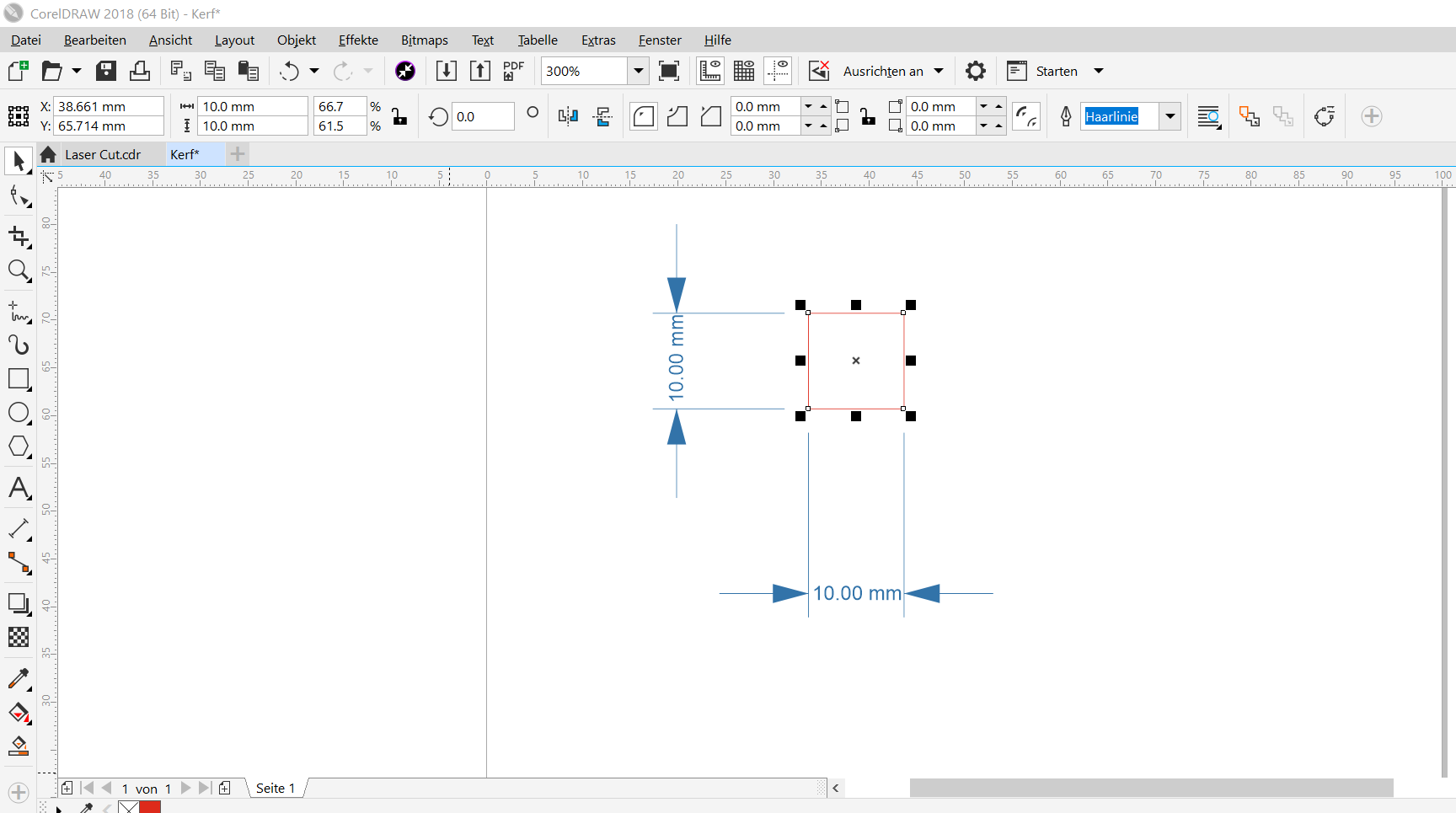
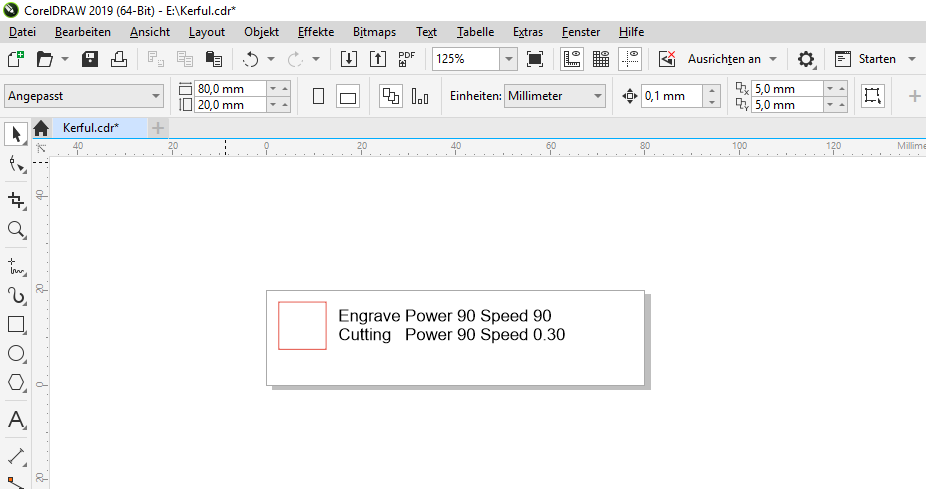
In order to calculate the kerf, I created in CorelDraw a 10 mm square. After that I cut it in a 3mm plywood using Trotec Speedy 100 laser cutter. Please note that I played some gymnastics with the cutting parameters to understand how different parameters (such as speed and power) affect the cutting. Finally, I measured noted the size of the cut square. The variation between the original intended size (10mm) and the cut piece are documented. To calculate the kerf, I used the formula below:
(Size of the square - size of the hole)/2
Few things to note is that, I changed the colour of the border to red, because that is the default colour for cutting on our Laser cutter. This can be changed in the settings in case you are allergic to colour red. In addition, I also changed the font size to ‘Hairline’. These are the two useful information I can share with you right now.
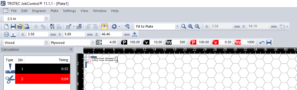
One of the decisions I made was to conduct two different test. Which is to check the effect of the Power on the Speed in an inverted form. That is, for Engraving When Power is 100, then Speed will reduced to 10 (inverted), vice versa.
In addition, for the cutting speed, I discovered that lowest value for the speed is 0.01, while the highest as mentioned above is 10. So, in order to save time, I decided to move in increments of 0.50 till I get to speed value 1.00. Same goes for the cutting process.
Test Result
So after trying different paraments where I fixed the Engraving Power at 100 and alternated the velocity from 10 to 50. I discovered that the faster the velocity of the engraving, the less clearer it becomes. As well as the higher the power the more burnt the job becomes.
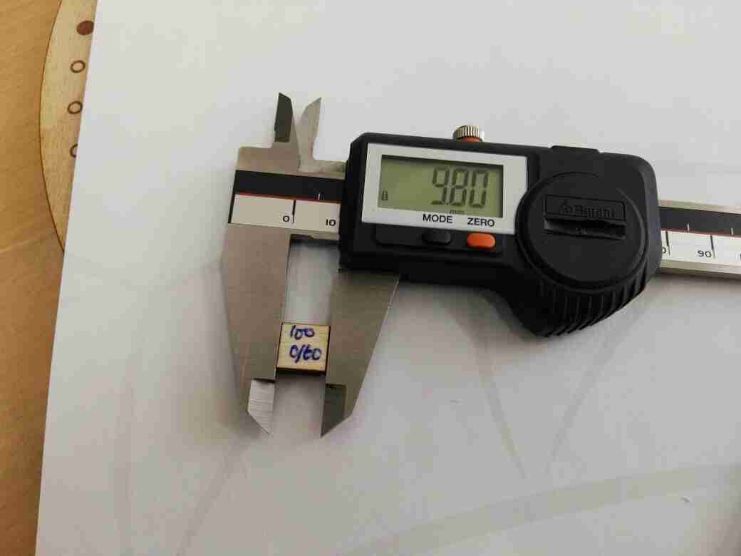
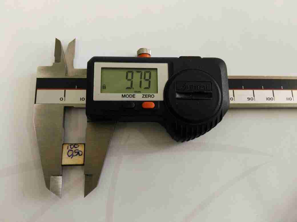
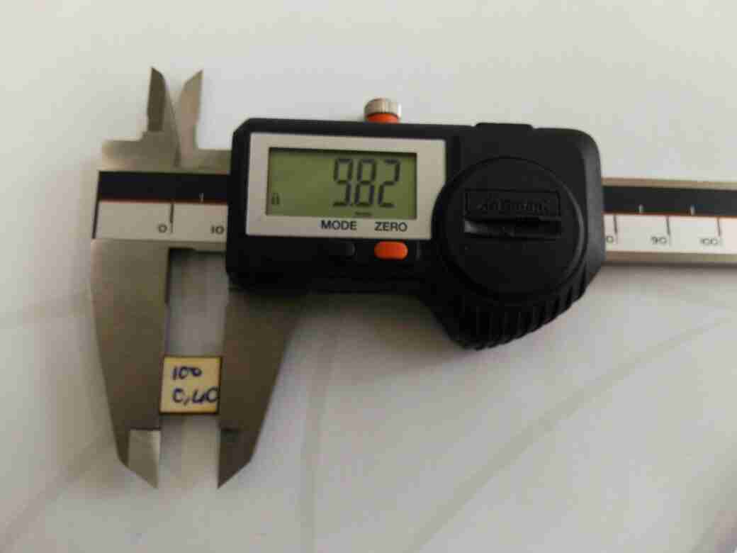
With regards to the cutting process, I used four different paramters. These are:
-
Power: 100, Speed:0.60
-
Power: 100, Speed:0.50
-
Power: 100, Speed:0.40
-
Power: 90, Speed:0.30
Kerf Calculation
Based on the formula for calculating the Kerf presented above. The Bulleted section below shows the Kerf calculation of the machine: - Power: 100, Speed:0.60. Kerf = 0.21 - Power: 100, Speed:0.50. Kerf = 0.20 - Power: 100, Speed:0.40. Kerf = 0.20 - Power: 90, Speed:0.30. Kerf = 0.28
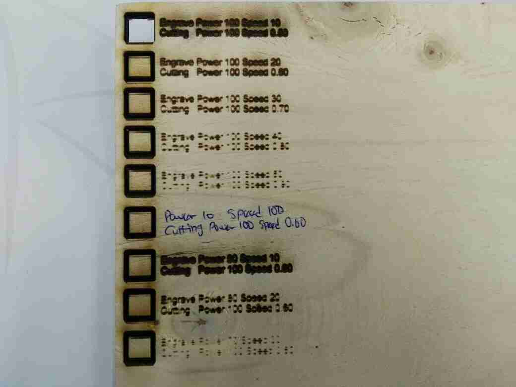
The pictures below shows their results.
Observation
After making the first test with Speed = 100, Power = 90, I discovered that nothing was showing. So I decided not to proceed with higher speed.
So after doing the first test, it became apparent that something was wrong with the ‘Autofocus I thought I had already set as ‘On’. So what I did was to use the opportunity to clean the lens and the mirror, and go for another test. Below you will find the result of the new test, now with the autofocus consciously set at all times.
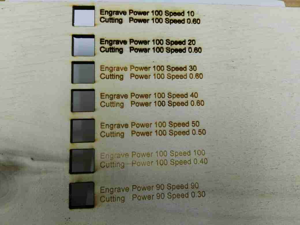
Depending on your preference, I think the best option according to the chart presented in the picture above is the parameter with Power = 100, Speed = 50 or 40. I also think this should still be fine for Power = 100 to 80 with the Speed = 50 or 40.
Large Laser Cutter
For our group assignment and our first use of the laser cutter machine , I’ve learned some safety rules which are:
- Never leave the laser cutter unattended.
- Only cut materials approved by your instructor.
- Keep the lid closed at all times, unless loading material while the laser is turned off.
- Clean up debris in the laser cutter.
- Identify the fire extinguisher and fire blanket
First we identified the laser cutter parameters
- Tool: Laser cutter CO2
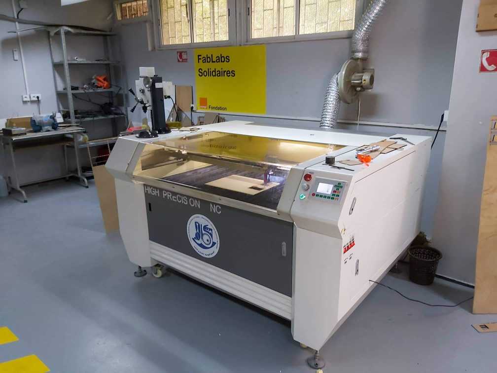
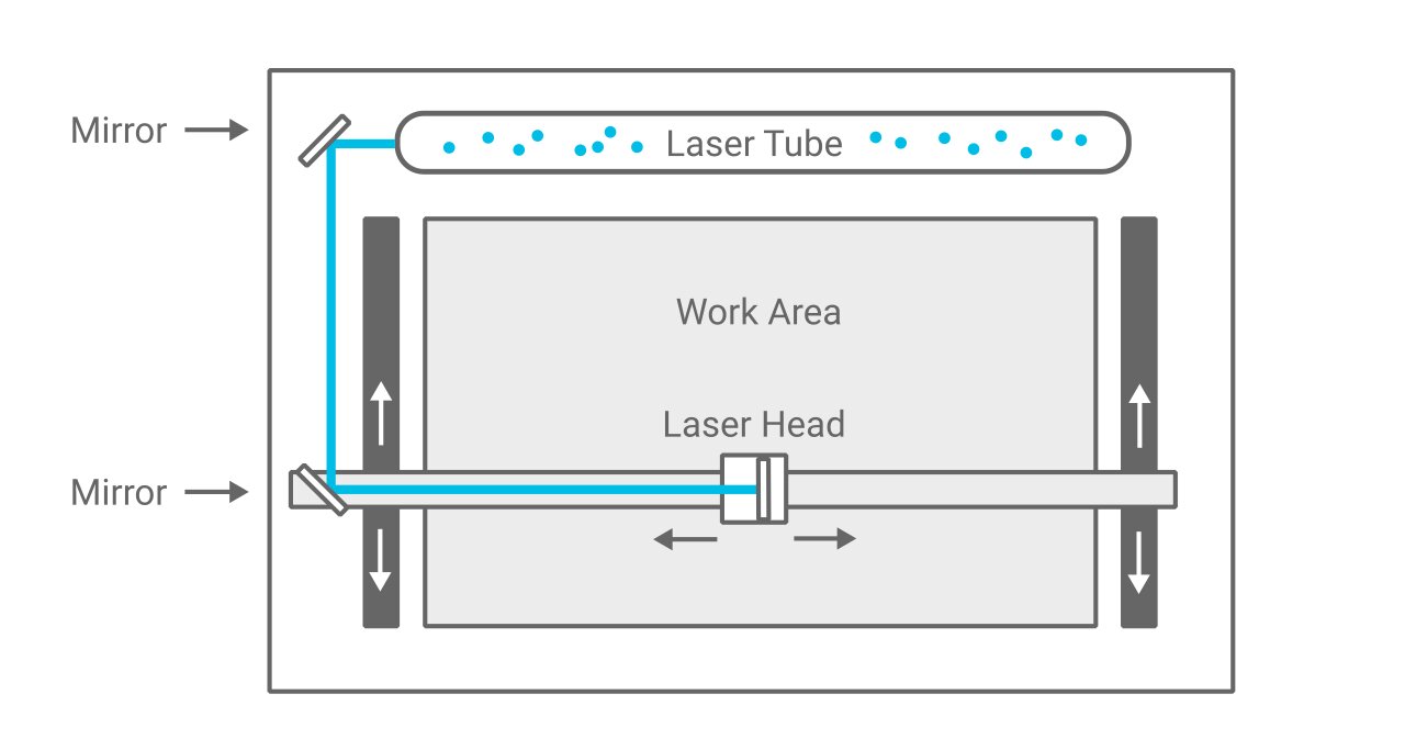
In a CO2 laser cutter machine, the laser beam is created in a tube filled with CO2 gas. Next, with the help of mirrors and lenses, the laser beam is directed to the laser head and focused on the material surface. Electronically controlled motors move the laser head to cut or engrave the desired shape into the material of the workpiece. The shape is defined by an input file which can be a vector or raster image

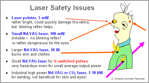
Class: 3R (for this class, lasers are considered safe when handled carefully. There is only a small hazard potential for accidental exposure. For visible-light lasers, Class 3R lasers’ output power is between 1 and 4.99 milliwatts.
- Laser Power: 100 watt.
- Model: Golden Sign GS9070
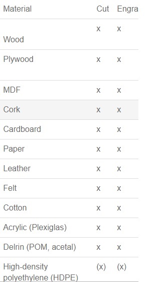
For the materials we used:
- Plywood/Mdf 4mm
- Cardboard 6mm
- Plexigrass 5mm
For the setup of the machine we folowed these steps :
- Decide what material you want to cut or engrave.
- Choose an image to cut or engrave onto your chosen material
- Upload the image into software that is compatible with your laser cutter
- Set the dimensions of your image to match the size of your material
- Place the material in the centre of the laser cutting mat
- Set the lens height
- Switch ON the laser
- Switch ON the pointer
- Unlock X/Y motor axes
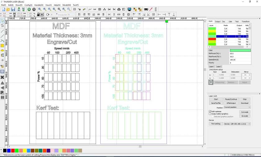
After charactirizing the machine ,we decided to made our own test template laser , we choose to test cutting and engraving at the same time on MDF 3mm with diffrent speed and laser power for each rectangle test . To design the 2D template on Fusion 360 we have drawn 9 rectangular pieces (10mm each) for 10 vertical cuts.
After the designing step we used RDworks or LaserCAD to manage the cutting plan. The software can set parameters (setting) like power, speed and frequency per color or for the whole job, but only lines thinner than dpi-dependent threshold are recognized to be cut. Since our template required so many different settings, we had to use multiple colored layers to stack all the power settings. RDworks has a limited number of layers and so it became very time consuming to cut even one template.
Here it is the final result
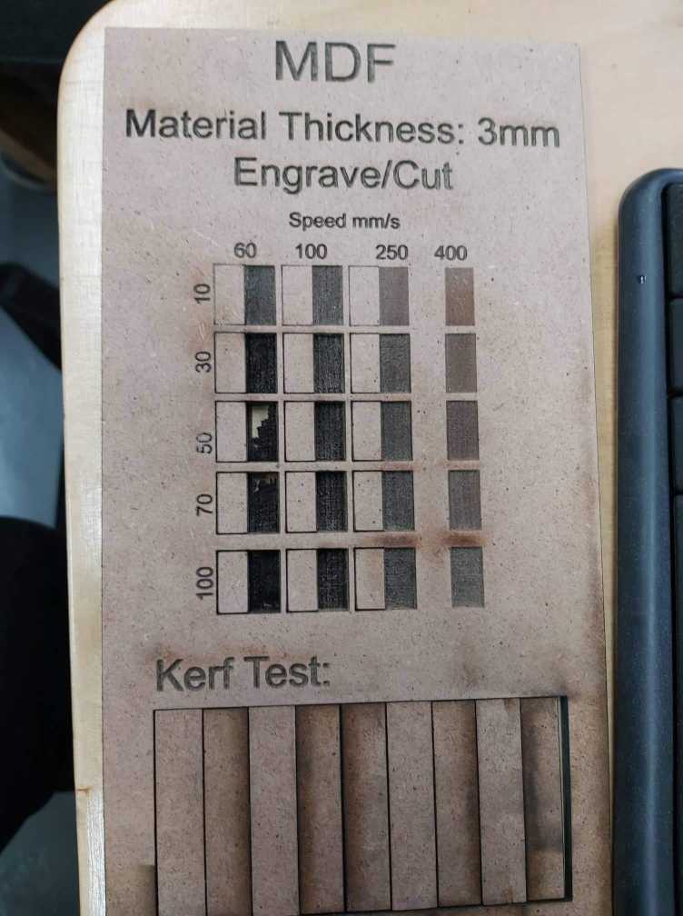
To begin characterizing the laser cutter it is first important to understand what the Kerf is. Kerf is defined as the width of material that is removed by a cutting process. is determined by material properties and thickness, the focal length of the lens and the gas used while cutting . to identify the kurf we have designed a simple test .We have drawn 9 rectangular pieces (10mm each) for 10 vertical cuts. This for make an average on the long distance
Finally we obtained 0.3mm as kerf . I will take it into consideration to design properly my model for the individual assignment.
So in other words THE KERFis the amount of wood removed by the laser cutter as it burns through the wood. Thicker pieces of wood or plywood which has glue require a slower laser cutter speed and higher power will burn away more wood, making the kerf wider.