'The well brought-up man eats with one hand even when he is hungry.'
African Proverbs
Embedded Programming
Just like other assignments, this week we also have a combination of group and individual assignments to complete.
Group Assignment
Compare the performance and development workflows for other architectures.
You can view the Group Assignment on this Link.
Individual Assignment
The individual assignment are as follow:
Individual Assignment
Data 'Scheisse'
The objective of this is to read and explain a microcontroller data sheet. In case you are wondering what 'Scheisse' means, it means 'Number 2' in German. Why being vulgar? Well, depending on how you look at it, reading the data sheet for a novice like myself is like playing 'Hide and Seek' with a sniper. Another reason is due to the incomprehensible aspect that a chip that is as cheap as $4 would have a functionality that covers 500 pages (Shoot me already!). Despite the complexity of this sheet, it is really helpful to learn how to understand the data sheet and what it contains. So in this section, I will explain from my understanding Da Vinci codes buried in this sinkhole called 'Data Sheet'.
What is a Data Sheet?
A datasheet is a document that summarizes the performance and other characteristics of a product, machine, component (e.g., an electronic component), material, subsystem (e.g., a power supply), or software in sufficient detail that allows a buyer to understand what the product is and a design engineer to understand the role of the component in the overall system (Reference). In addition, a datasheet is created by the manufacturer and begins with an introductory page describing the rest of the document, followed by listings of specific characteristics, with further information on the connectivity of the devices.
To accomplish this assignment, I will be reviewing the data sheet of ATMega328P. For us to be on the same page, please also visit this LINK.
Overview
ATmega328P is a low-power CMOS (Complementary Metal Oxide Semiconductor) 8-bit microcontroller based on the AVR enhanced RISC architecture. By executing powerful instructions in a single clock cycle, the ATmega328P achieves throughputs close to 1MIPS (Million of Instructions Per Seconds) per MHz ( Explanation of Instruction Per Seconds). This empowers system designer to optimize the device for power consumption versus processing speed.
To be honest, the perfect thing to depict what is going on in my head while reading this data sheet is the picture below. SOS!

Summoning the courage to proceed with the review of the data sheet proves a proverb which says 'If you stop to throw stones at every dogs that barks, then you will never get to your destination.' So I had to encourage myself to make understanding an average data sheet my hearthrob!
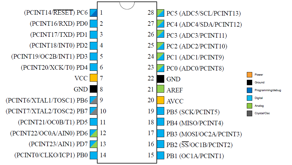
ATMega328P is a 28-pin microcontroller, and each pin has a particular function. Some of these functions differes while some performs the same functionalities. The picture below perfectly explains this.
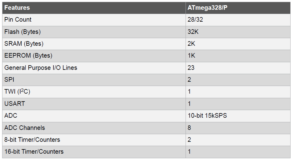
The ATmega328P provides the following features: 32Kbytes of In-System Programmable Flash with Read-While-Write capabilities, 1Kbytes EEPROM (Electrically Erasable Programmable Read-Only Memory), 2Kbytes SRAM (Static Random-Access Memory), 23 general purpose I/O lines, 32 general purpose working registers, Real Time Counter (RTC), three flexible Timer/Counters with compare modes and PWM, 1 serial programmable USARTs (Universal Synchronous/Asynchronous Receiver/Transmitter), 1 byte-oriented 2-wire Serial Interface (I2C), a 6-channel 10-bit ADC (Analog-to-Digital Converter), a programmable Watchdog Timer with internal Oscillator, an Serial Peripheral Interface (SPI) serial port, and six software selectable power saving modes. The Idle mode stops the CPU while allowing the SRAM, Timer/Counters, SPI port, and interrupt system to continue functioning. This is represented in the picture below.
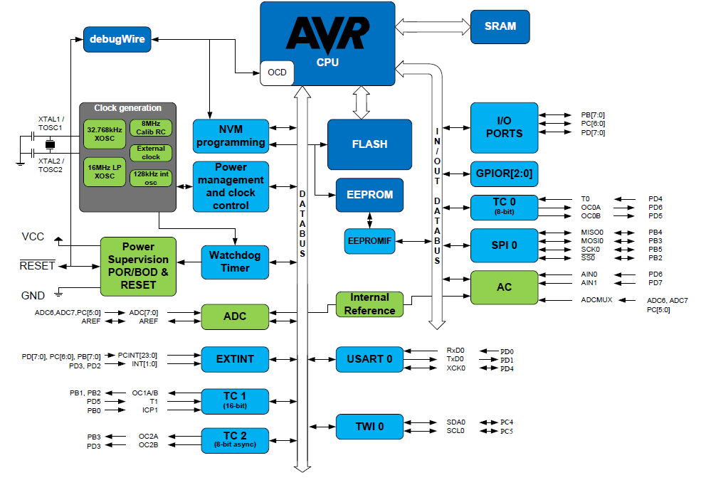
Block Diagram
A block diagram is a diagram showing in schematic form the general arrangement of the parts or components of a complex system or process, such as an industrial apparatus or an electronic circuit. In this case, the block diagram will explain Architecture of the Microcontroller. The Atmel AVR® core combines a rich instruction set with 32 general purpose working registers. All the 32 registers are directly connected to the Arithmetic Logic Unit (ALU), allowing two independent registers to be accessed in a single instruction executed in one clock cycle.
Pin Descriptions
| Name | Description |
|---|---|
| VCC | Digital supply voltage. |
| GND | Ground |
| Port B (PB[7:0]) XTAL1/XTAL2/TOSC1/TOSC2 | Port B is an 8-bit bi-directional I/O port with internal pull-up resistors (selected for each bit). Note: XTAL is an informal abbreviation for Crystals. TOSC means Time of OSCillation. |
| Port C (PC[5:0]) | Port C is a 7-bit bi-directional I/O port with internal pull-up resistors (selected for each bit). |
| PC6/RESET | If the RSTDISBL (Reset Disable) Fuse is programmed, PC6 is used as an I/O pin. Note that the electrical characteristics of PC6 differ from those of the other pins of Port C. If the RSTDISBL Fuse is unprogrammed, PC6 is used as a Reset input. |
| Port D (PD[7:0]) | Port D is an 8-bit bi-directional I/O port with internal pull-up resistors (selected for each bit). |
| AVCC | AVCC is the supply voltage pin for the A/D Converter, PC[3:0], and PE[3:2]. It should be externally connected to VCC, even if the ADC is not used. If the ADC is used, it should be connected to VCC through a low-pass filter. Note that PC[6:4] use digital supply voltage, VCC. |
| AREF | AREF (Analog Reference) is the analog reference pin for the A/D Converter. |
| ADC[7:6] (TQFP and VFQFN Package Only) | In the TQFP (Thin Quad Flat Package) and VFQFN (Very Thin Quad Flat Package) package, ADC[7:6] serve as analog inputs to the A/D converter. These pins are powered from the analog supply and serve as 10-bit ADC channels. |
What I have done here is to try explain some acronyms that almost frustrated Fab out of my Academy. So I hope this also helps you too.
Programming
It is now time for me to face my fears of programming!
The objective is to program our boards to perform specified functions, and this should also be done with two or more Programming languages.
Before I finish this assignment, I will first give a brief information about the IDE (Integrated Development Environment) I will be using. For this part of the assignment, I will be using Arduino IDE. There are still some other powerful IDEs that could be used to program a Microcontroller, some of which includes Atmel Studio. Below I will show how to download, install and setup the Arduino IDE.
Arduino IDE
NOTEArduino is a programming language which is a derivative of C programming language (C is a powerful general-purpose programming language. It can be used to develop software like operating systems, databases, compilers, and so on.).
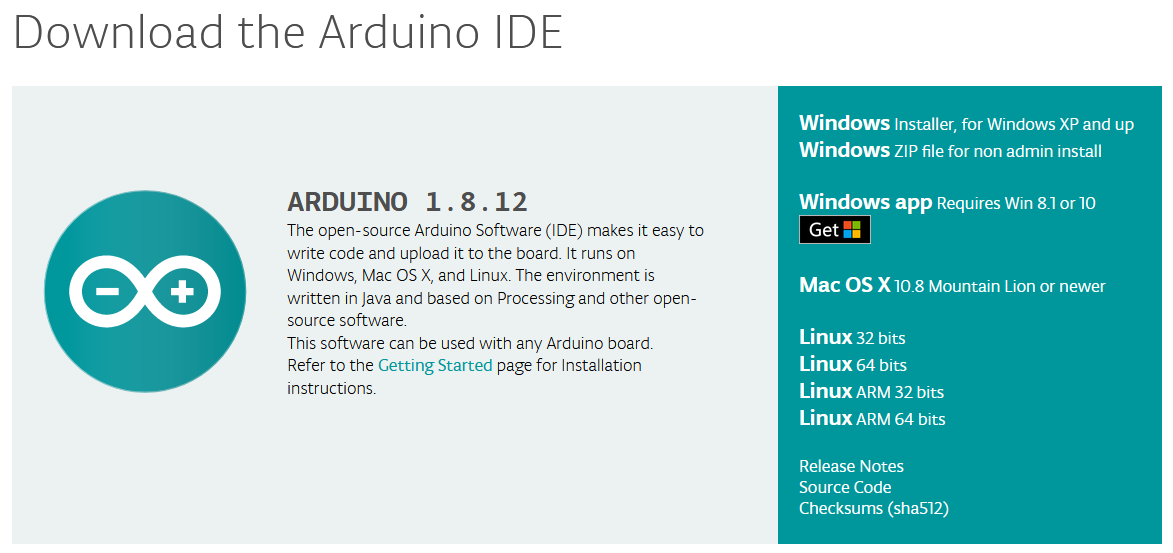
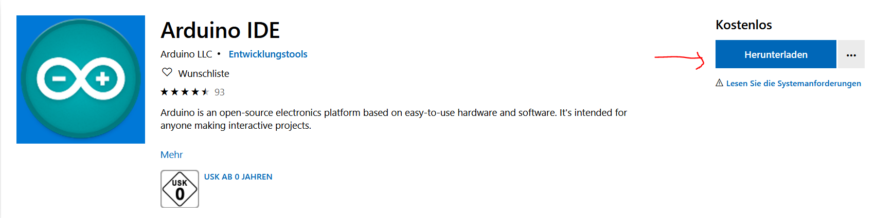
Download: to download Arduino IDE, 'Click Here'. After which you should select the software to download based on the operating system of your computer. Please refer to the picture below.
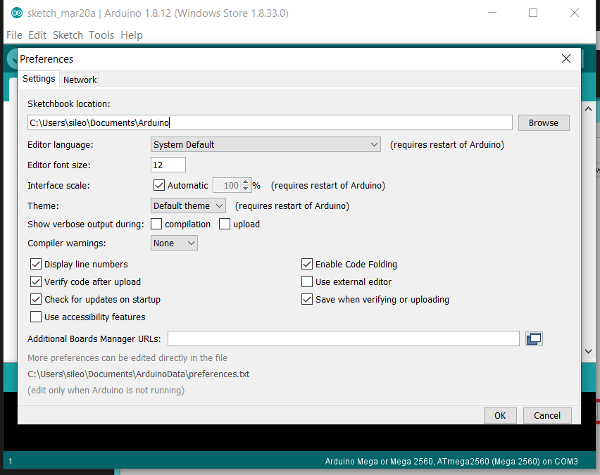
After installation, open the software. Then to make some basic changes, click File -> Preferences. When you are in Preference, you can change the following changes on the editor, such as language, font size, display line numbers as well as to check for updates to name a few. After which you should click 'OK'.
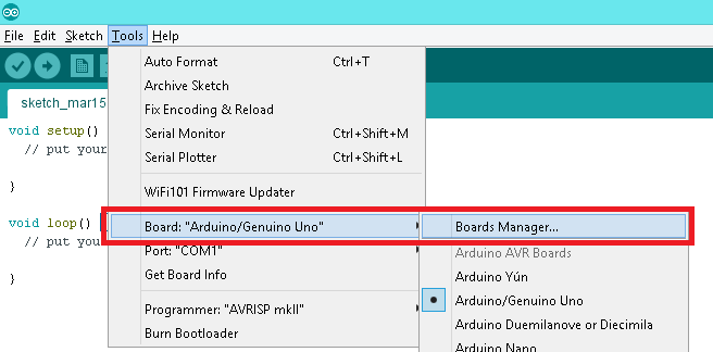
After this, before you proceed, you should select the board which you are to program by selecting Tools -> 'Board', then select the board from the options shown in the scroll down option.
After this, we are ready to start programming our MicroController.
TEST
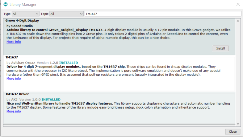
To make a quick test, I decided to test the 7-Segment 4 Digit display that has been lying idle in my apartment since 17AD. What I did was to download the master file from this Github Link. NOTE: Please be also informed that the link also contains the library for the digital display. To add a library on your Arduino IDE, just select 'Sketch' -> 'Include Library' -> 'Manage Library'. Then on the search pane of the new window shown (Please see the illustration below), type in the name of the library you would like to add. In my case the library was already included. All I did was just to click 'Install' so as to install it.
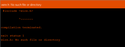
In case you are wondering what would happen if a library is not installed, well think no further! Your code will not run, and you will also find this annoying error message that says 'TM1637Display.h: No such file or directory.' (See picture below). Trust me, nothing is more annoying than finding error messages when compiling and uploading a code. If you can keep a secret, that is the real reason why I gave up programming in my 'Final Year'!
The next thing I did after going through all the stress of installing the library, I mean in the midst of CORONA virus outbreak (Just kidding!), I extracted the master file folder, then I opened the example folder on the master file, then I finally opened the Arduino code for the test.
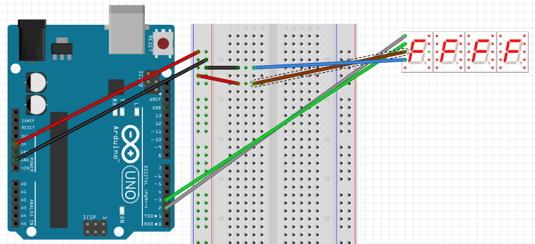
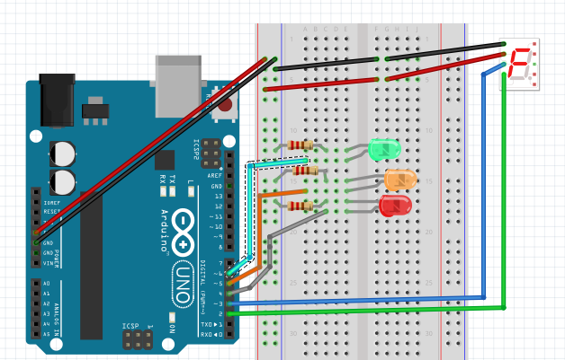
This test is relatively easy. You literally do not need anything but an Arduino board with the Digital display component, and some jumper wires. Therefore for this test, I created the connection as depicted in the picture below. Please be informed that this layout was created using Fritzing, which can be downloaded from this Website.
Code
Below you will find the code and a little information on what it means from the mouth of a Codingphobic person like myself. If you are not satisfied with my explanation, I suggest you take up a challenge by reading 'Arduino for Dummies'. I dare not call you a 'Dummy', that is just the title of the book.
The first thing you will notice is the 'Arduino.h'. What this means is that Arduino has a header file (.h) which contains definitions for the library, which is a listing of everything that's inside, including commands (functions) and needed variables ( Reference).
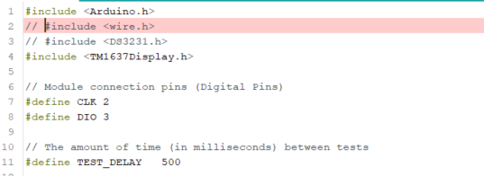
The next thing worth talking about in the code is the keyword '#define'. This #define directive allows the definition of macros within your source code. In this case, it assigns the digital pins 2 and 3 on the Arduino Uno board to CLK (clock) and DIO (Digital Input and Output) respectively. The next #define assigns a value 500 milliseconds to the variable 'TEST_DELAY'.
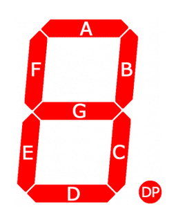
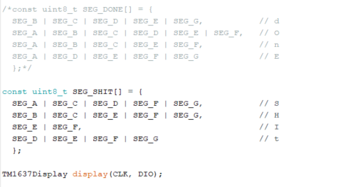
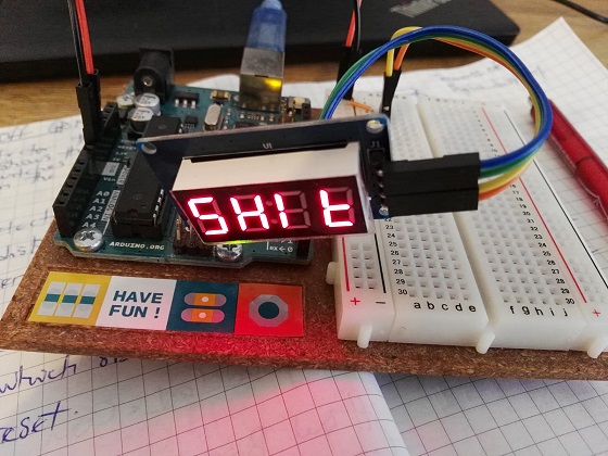
The code above also shows how the segments of the digital display is accomplished. '//' this sign shows that the text is a comment. This can also be used to make a text nonprogrammable or executable or better still the computer understands and treats any text after the double-forward slash (//) as a text rather than a code. You can review the pictures below to get a better understanding of the code. Pardon my manners, I had to test out my level of understanding of the code. Hence, the reason for creating the 'S' word!
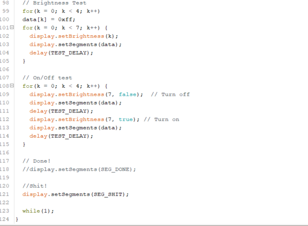
The last part I will show is the part depicted in the picture below that sets the brightness of the Digital display component. This was done using a 'For Loop'. Note: 'a for-loop (or simply for loop) is a control flow statement for specifying iteration, which allows code to be executed repeatedly.' This also applies to other loops, such as 'While Loop'.
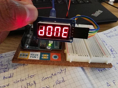
Test Result
For the test, I had to comment out some parts of the code which for my purpose does nothing than to waste my precious time and enjoyment of coding once again. The pictures below shows the outcome of the quick test.
Traffic Light Assignment
To proceed with the assignment, once again I decided to go easy by making a Traffic Light. The logical analysis of the task is as follows:
Well, Logic and reality are two different things! I pray the god of coding smiles down on me! BITTE!!!!
Connection
To be honest, I have been making a sizable progress reading the datasheets of almost all the electronic components I have. So I can say on an average that I am getting better at it.
From my little knowledge, I think I will need the following components:
The code for the traffic light, at least according to my present knowledge, is given below. One confession that I must make is that I used some helps from books (Arduino Projects Book) and some Youtube videos to get a knack of this assignment.
        TM1637Display display(CLK, DIO);

        int LED1 = 6;
        int LED2 = 5;
        int LED3 = 4;
        //int buttonPin = 12;

        int Value;
        int Value1 = 1;

        void setup() {
            // set pins to output/input
            pinMode(LED1, OUTPUT);
            pinMode(LED2, OUTPUT);
            pinMode(LED3, OUTPUT);

            Serial.begin(9600);  //Start the serial connection with the computer
        }

        void loop() {

          // Reading value from the Serial monitor
          Value = Serial.read();    //

          int k;
          uint8_t data[] = { 0xff, 0xff, 0xff, 0xff };
          display.setBrightness(0x0f);

          // All segments on
          display.setSegments(data);
          delay(500);

          // On/Off test
          for(k = 0; k < 4; k++) {
            display.setBrightness(7, false);  // Turn off
            display.setSegments(data);
            delay(500);
            display.setBrightness(7, true); // Turn on
            display.setSegments(data);
            delay(500);
          }

        //for(Value = 0; Value < 3; Value++)   {
        //if (Value == Value1) {

        Serial.println("Please enter a value above.");

        while (Value = Value1) {

          //Green Traffic Light
          digitalWrite(LED1, HIGH);
          digitalWrite(LED2, LOW);
          digitalWrite(LED3, LOW);
          //GO!
          display.setSegments(SEG_GO);
          Serial.print(Value);
          Serial.println(" this is what I received");
          delay(7000);

          //Orange Traffic Light
          digitalWrite(LED1, LOW);
          digitalWrite(LED2, HIGH);
          digitalWrite(LED3, LOW);
          //ATTN!
          display.setSegments(SEG_ATTN);
          Serial.print(Value);
          Serial.println(" this is what I receive");
          delay(3000);

          //Red Traffic Light
          digitalWrite(LED1, LOW);
          digitalWrite(LED2, LOW);
          digitalWrite(LED3, HIGH);
          //STOP!
          display.setSegments(SEG_STOP);
          Serial.print(Value);
          Serial.println(" This is what I receive");
          delay(5000);

        }

        }
C Programming
Now, the last part of the assignment is to convert these codes written in Arduino to C Programming language. The code for the C programming language will be appended below.
        #define F_CPU 16000000L
          #include
          #include
          #include
          #include

          TM1637Display display(PD2, PD3);

          //This is the sequencing of the segments that will represent the green light of the traffic

          const uint8_t SEG_GO[] = {
            SEG_A | SEG_B | SEG_C | SEG_D | SEG_F | SEG_G,   // G - All these sequence is meant to spell out the alphabet G
            SEG_A | SEG_B | SEG_C | SEG_D | SEG_E | SEG_F    // O - All these sequence is meant to spell out the alphabet O
            };

            //This segment will be used to represent the amber light, which is to warn the driver to slow down or be expectant of the red light

          const uint8_t SEG_ATTN[] = {
            SEG_A | SEG_B | SEG_C | SEG_E | SEG_F | SEG_G,   // A
            SEG_D | SEG_E | SEG_F | SEG_G,                   // t
            SEG_D | SEG_E | SEG_F | SEG_G,                   // t
            SEG_A | SEG_B | SEG_C | SEG_E | SEG_F            // n
            };

            //This is the sequencing of the segments that will represent the RED light of the traffic

          const uint8_t SEG_STOP[] = {
            SEG_A | SEG_C | SEG_D | SEG_F | SEG_G,           // S
            SEG_D | SEG_E | SEG_F | SEG_G,                   // t
            SEG_A | SEG_B | SEG_C | SEG_D | SEG_E | SEG_F,   // O
            SEG_A | SEG_B | SEG_E | SEG_F | SEG_G            // P
            };


          int main(void) {

            DDRD = (1<>PD4); //This indicates that when no signal or input is read from the Port 4, then the Red LED should remain off
            PORTD = (0>>PD5); //This indicates that when no signal or input is read from the Port 5, then the Yellow LED should remain off
            PORTD = (1>>PD6); //This indicates that when a signal or input is received from the Port 6, then the Green LED should come on
            //GO! Then the GO signal is displayed on the display
            display.setSegments(SEG_GO); //This function calls the SEG_GO defined above
            _delay_ms(7000); //This controls the timing of the light, which means the light will be on only for 7 seconds

            //Orange Traffic Light
            //This switches on the yellow LED
            PORTD = (0>>PD4); //This indicates that when no signal or input is read from the Port 4, then the Red LED should remain off
            PORTD = (1>>PD5); //This indicates that when a signal or input is received from the Port 5, then the Yellow LED should come on
            PORTD = (0>>PD6); //This indicates that when no signal or input is read from the Port 6, then the Green LED should remain off
            //ATTN! Then once the yellow signal is on, ATTN is displayed on the display
            display.setSegments(SEG_ATTN); //This function calls the SEG_ATTN defined above
            _delay_ms(3000); //This controls the timing of the light, which means the light will be on only for 3 seconds

            //Red Traffic Light
            //This switches on the red LED
            PORTD = (1>>PD4); //This indicates that when a signal or input is received from the Port 4, then the Red LED should come on
            PORTD = (0>>PD5); //This indicates that when no signal or input is read from the Port 5, then the Yellow LED should remain off
            PORTD = (0>>PD6); //This indicates that when no signal or input is read from the Port 6, then the Green LED should remain off
            //STOP! Then once the Red signal is on, STOP is displayed on the display
            display.setSegments(SEG_STOP); //This function calls the SEG_STOP defined above
            _delay_ms(5000); //This controls the timing of the light, which means the light will be on only for 5 seconds

          }

            return (0);

          }
The tab titled 'C_Equivalent_of_TestDisplay' which is beside the 'TestDisplay' contains the code for the C programming version of the initial code written above. This officially marks the end of this assignment, but definitely not the end of my newfound hunger to break the programming jinx.
Arduino Code - Hello Board
To test my skills, I simply sent a simple sketch to my Hello Board. What use is it if it cannot blink a simple Hello. The code tested is below:
// the setup function runs once when you press reset or power the board
          //This code does nothing more than the basic.
          //It blinks upon the receipt of any signal from the Push button

          const int LED = 7;
          const int Switch = 0;
          int Press = 0;

          void setup() {
            // initialize digital pin LED_BUILTIN as an output.
            pinMode(LED, OUTPUT); //I changed this to 7, since I used PA7 on ATTINY84 microcontroller
            pinMode(Switch, INPUT);
          }

          // the loop function runs over and over again forever
          void loop() {
            Press = digitalRead(Switch);

            if (Press == HIGH){
              digitalWrite(LED, HIGH); // turn the LED on (HIGH is the voltage level)
              delay(1000); // wait for a second
            }
            else {
              digitalWrite(LED, LOW); // turn the LED off by making the voltage LOW

            }
          }
C Code - Hello Board
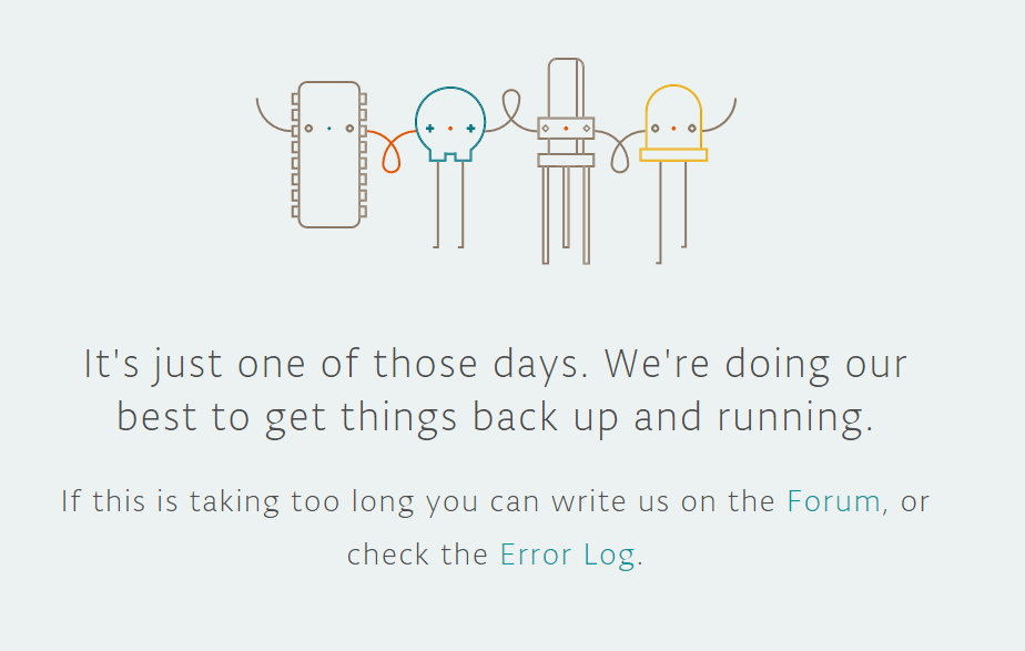
So many errors just for a simple task. I first inputted the code as an online Arduino sketch. But for so many weird reasons, it chose not to work. Below was what it was displaying on my documentation page.
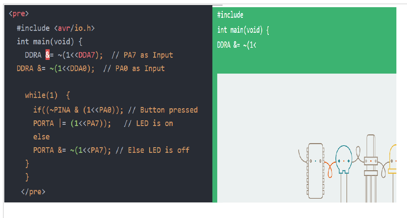
So I tried to insert it as a pre tag, but this also didn't display it as expected. It only displayed the code up until the third line of code. As can be seen from the picture below.
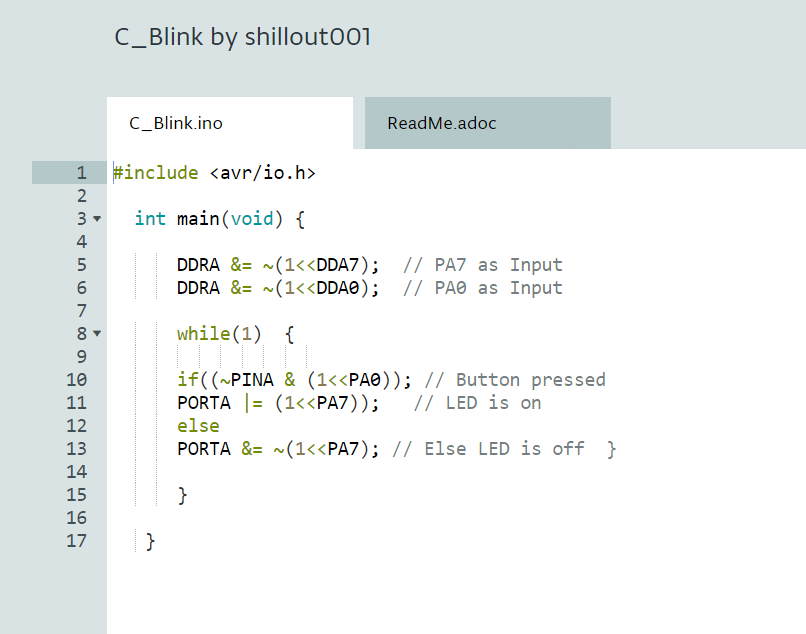
After all these sprints, I decided to simply include the code as a picture. Which can be found below.
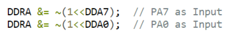
How the code work.
Since Port 7 and Port 0 are assigned to the button and LED ports on the microcontroller. So in the code, these ports were written to function as such. See picture below
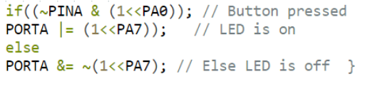
Then, if the pushbutton is pressed, then the LED should come on. Else, it should not come on. This is included in the picture below.
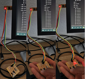
Hero Shot
Below are some snapshots of the program.
Click on this LINK to download the code for the Hello World assignment.