'A wise person would pick a large bird rather than a tiny one for a sacrifice for prosperity.'
African Proverbs
Electronics Design
This week, we are slowly progressing into learning how the Makers' world function. It is only a matter of time before we would be endowed with the knowledge on 'How to Make Almost Anything'! So let's get CRACKING!
The art of Electronic design entails the analysis and synthesis of electronic circuits (Reference). This means that a would-be electrical engineer (in this case my humble self - Babasile Daniel) must possess the ability to predict the voltages and currents at all places within the circuit. So how does one go about this great electrical analytical skills? In case that is what you are also thinking about, do not be too hasty, because I also have been asking my Fab Instructor (Daniele Ingrassia) the same question. All he keeps saying is with time you will be good at it. The only information he shared with me for now is to study and decipher the cryptic language written in the components datasheet. Wow! Thank you very much Daniele! What a good way to boost someone's confidence!
So if you are not as lazy as I am, just try to review the datasheet as recommended by our Gurus. However, this weeks task is about designing or redesigning an existing electronic circuit. So you can still relax a bit for now, till you get a glimpse of Armageddon.
To do this, we need to utilise some Circuit designing softwares. Some of which includes Eagle from Autodesk, KiCAD, LibrePCB, as well as EasyEDA just to name a few. By now you should know that I will opt for the easiest option which is Eagle. However, I will try to use two extra softwares to justify my preference for Eagle.
You can get better information about the week's agenda on this Fab Link. In addition, since we are in the OhmMG era, I will briefly explain the Ohm's Law below. This is imporatnat because 'Resistance' is a norm in human life. Either in the form of resistance to Political tyrants or illogical social impendium. A form of resistance is not an overall evil.
OhmMG!
Resistor is a passive two-terminal electrical component that offers some forms of resistance to electric current (I). The resistor's ability to reduce the current is called resistance and is measured in units of ohms (symbol: Ω) (Reference). In electronic circuits, resistors are used to reduce current flow, adjust signal levels, to divide voltages, bias active elements, and terminate transmission lines, among other uses (Reference).
So it is time to show my mathematical prowess. To do that I will show you the Ohm's Law. Before loading and overloading you with all my mathematical jargons, I must first tell you that 'Ohm' symbolically represented by Ω, and which duly symbolises resistance, was named after German physicist Georg Simon Ohm (It is little wonder that the best cars and technologies are from Germany! Take it or leave it!), (Reference). Back from the unnecessary deviation, so What is Ohm's law?.
Ohm's law states that the voltage (V) across a resistor is proportional to the current (I), where the constant of proportionality is the resistance (R). This is depicted by the formula:
V = I * R

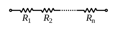
Resistors can be schematically represented by the picture below:

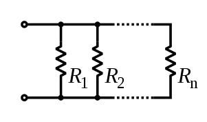
Resistors can be connected in two forms:
R = R1 + R2 + ... + Rn
1/R = 1/R1 + 1/R2 + ... + 1/Rn
Capacitor
“Like a battery, the human mind and body must be fully discharged to stretch their capacity.” With this quote, I would like to commence the last part of this not-so detailed explanations. So we proceed with what a capacitor is.
A capacitor is a passive electronic component with two terminals device that stores electrical energy in an electric field (Reference). The effect of a capacitor is known as capacitance (the ratio of the change in electric charge of a system, to the corresponding change in its electric potential.). A capacitor is a component designed to add capacitance to a circuit. The SI unit of capacitance is the farad (symbol: F), named after the English physicist Michael Faraday.
In addition to all the information presented above, a capacitor can only have two shades of gray (just playing with words). These are 'Polarized' and 'Nonpolarized'. The difference between these two components is that the Polarized have both positive and negative charge, while the Nonpolarized does not have any. The Nonpolarized is mostly used for the surface mounting devices. This means that any area can be soldered without taking cognizance of its polarity, while this is not the case for the Polarized version.


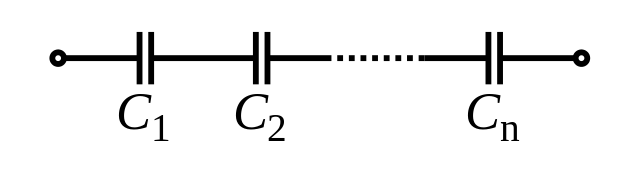
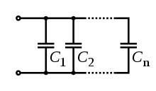
Capacitors can also be connected in two forms:
C = C1 + C2 + ... + Cn
1/C = 1/C1 + 1/C2 + ... + 1/Cn
This ends the explanation section. To view the assignment, click Assignment or simply go to the assignments sections below.