'Not every person in a flowing garment is a big man.'
African Proverbs
Output Devices
Unlike other assignments, this week we also does not include a group assignment. However, the workload covers the lessons covered till date. Which means that, by now you should be able to express, even up to 70%, the lessons you have learnt till date. The remaining 30% could come from enough practice ('Practice makes Perfect'), your instructor, and knowledgeable friends on the subject matter.
One thing also worth expressign here is that most of the things done here will be copied and pasted in the section that focuses on the Final Project itself. So DO NOT accuse me of plagiarism, because there is no such thing as self-plagiarism.
Group Assignment
We are back to the era of group assignments. The group assignment for this phase is to 'measure the power consumption of an output device'.
You can view the Group Assignment on this Link.
Individual Assignment
This week's individual assignment seems easy, but you know to be careful of a gentle river. That been said, the individual assignment is to ' add an output device to a microcontroller board you've designed, and program it to do something'. However, in the absence of a FabLab, we have been granted the permission to use an Arduino to display how the output device works.
Group Assignment
This will be populated after the lockdown.
Individual Assignment
Electronics Design
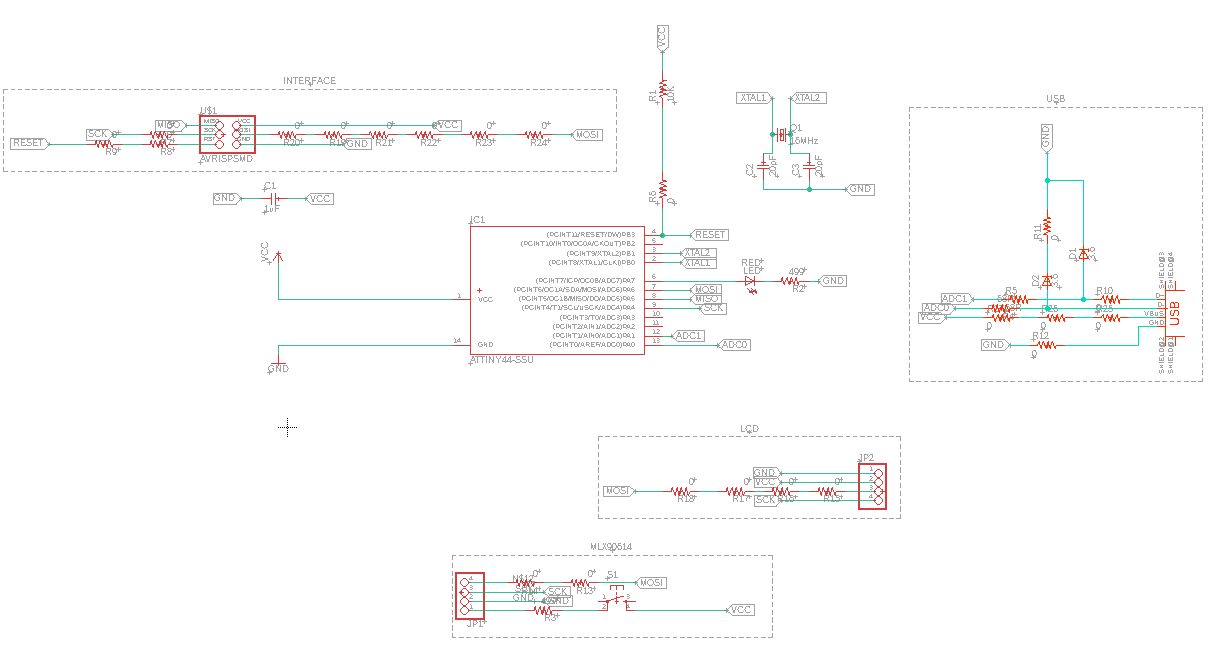
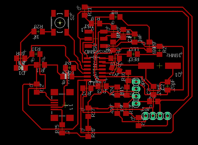
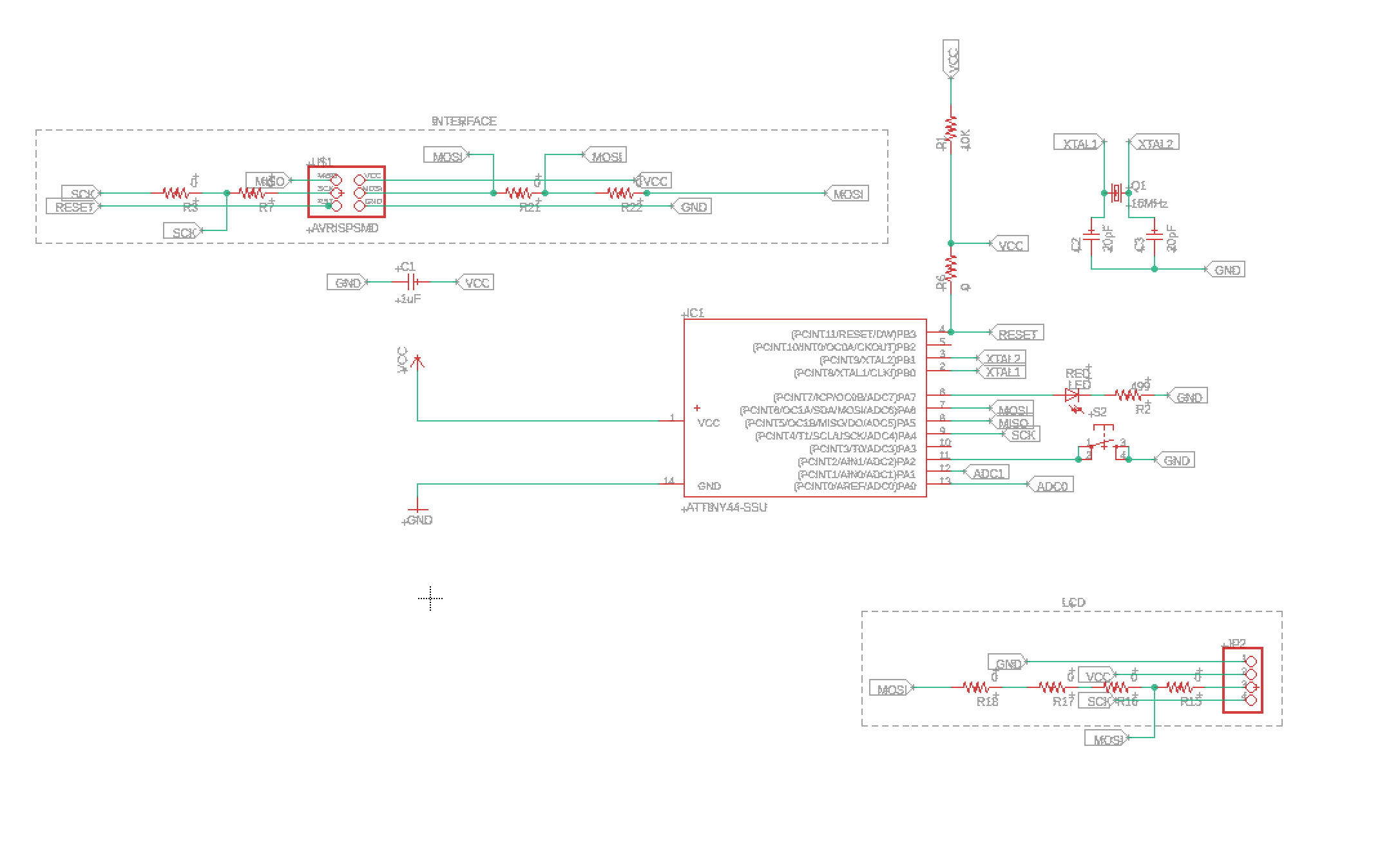
The circuit board I will design for this assignment is meant to test the temperature sensor that I will use for my final project. This will also utilize the a 16 x 2 LCD (I2C connection) as the output device. The purpose of the LCD is to display the readings of the temperature sensor.
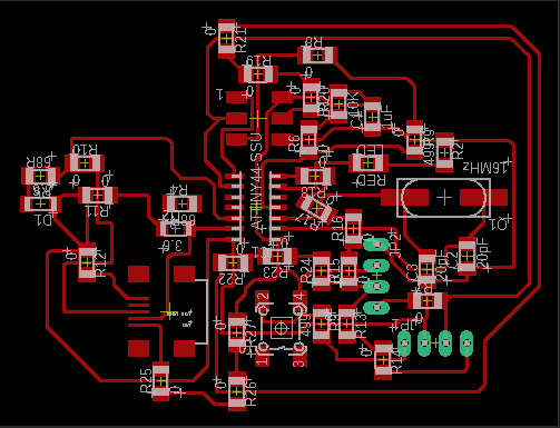
The illustrations below depicts the schematic and the board design of the electronic circuit designed for this week's assignment.
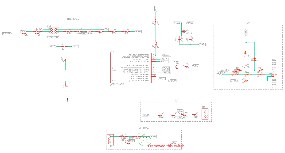
After going through the stress of routing the wires for the circuit bus, I discovered that I might have made another silly mistake with the connection of the switch. I think I should have assigned the switch to its own port, so I can send some commands to it. I will update that while still leaving the previous designs so you all can know that my Rome was not built in a day.
Luckily, I was able to fix the modifications easily (Pheeeeeew!). Below, you will find the pictorial representations of the modified design. Hopefully, everything should run fne.
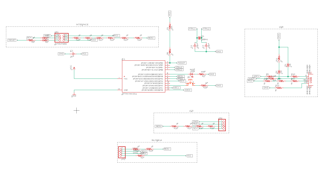
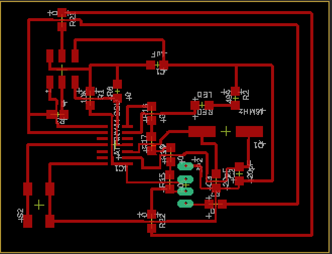
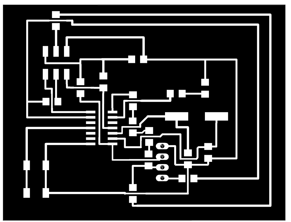
Design Modification
After series of talks and support from my Fab Guru, I made some changes to the initial design made. The changes made my work look a little bit neater. Many thanks to Daniele Ingrassia for his support. You can find pictures of the new design below.
Milling
After this, I milled the design, using the method used for milling the PCB in Electronic Production. This milling process includes saving the file as a dxf file. Then inserting it into Fusion, converting the dxf file to 2D, then extruding it to the thickness of the PCB board. After which I mill the board. This has been well documented in the Electronic production Assignment. Please use this LINK to access the methods used.
Code
In principle, the code that will be installed on the circuit board should function as follow:
If Switch is pushed
Temperature sensor starts working (measuring object), then
Displays measurement on the LCD display
Else, If Switch is not pushed
Display message on LCD "Push switch to start"
Insert code below
Arduino
Since my final project has at least 2 output devices, I decided to play with them for this week's assignment. The out put devices used for this weeks assignments are:
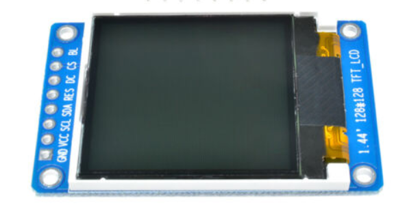
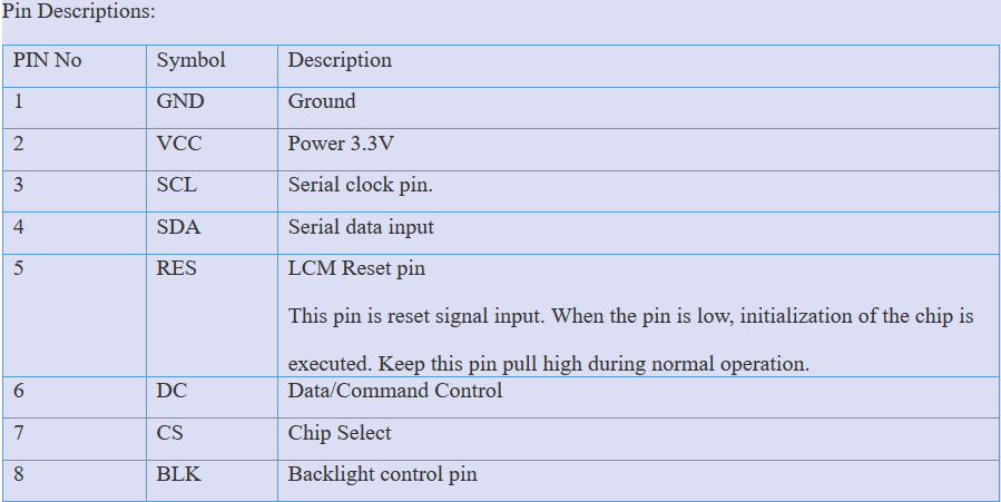
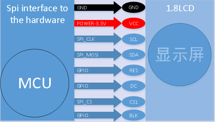
TFT LCD Display
It was more of an upheaval battle to get the LCD to work. My inadequate knowledge were glaring, but my resilience won the battle after frying one LCD display. So, I would advise other novice to always buy more than one component in case you are threading in an unfamiliar territory.
I assume you have installed the necessary library of the component. If not go to 'Sketch' -> 'Include Library' -> 'Manage Library', after this you have to search the name of the library from the list. Alternatively, from the 'Include Library', you could select 'Add .Zip Library' to manually add the library, which must first be downloaded from a website. The reason for this is because Arduino IDE sometimes does not have the required library.
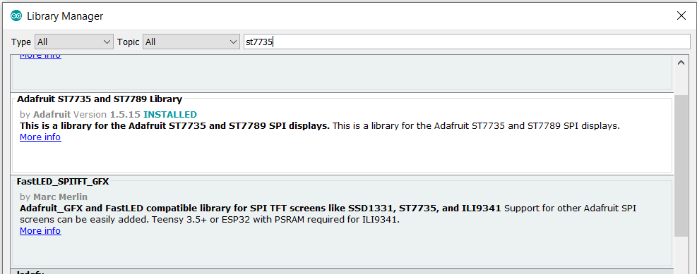
To use the added library, you just need to call it from the new sketch. This can be achieved by going to 'Sketch' -> 'Include Library', then scroll down and click the library from the list. This will automatically add the following header files to your sketch (See picture below).

After which you can start coding yourself away.
The Code
The code for the assignment is given below.
     // Library for Time of Flight
      #include "Adafruit_VL53L0X.h"
      #include

      // Library for Temperature sensor
      #include

      // Library for TFT LCD Screen
      //#include
      #include
      #include
      #include

      int PushButton = 3;
      int LaserPin = 4;
      int Trigger = 5;

      int PushState = 0;
      int TriggerState = 0;

      TFT_ST7735 tft = TFT_ST7735();  // Invoke library, pins defined in User_Setup.h

      Adafruit_MLX90614 mlx = Adafruit_MLX90614();
      Adafruit_VL53L0X lox = Adafruit_VL53L0X();

      void setup() {

        // This is used to setup the LCD
        tft.init();
        tft.setRotation(4); //You can rotate by changing from number 1 to 4

        // put your setup code here, to run once:
        Serial.begin(9600);
        Serial.println("Adafruit MLX90614 test");

        pinMode(PushButton, INPUT);
        pinMode(Trigger, INPUT);
        pinMode(LaserPin, OUTPUT);

        mlx.begin(); //Starts the Temperature sensor

        // wait until serial port opens for native USB devices
        if (!lox.begin()) {
          Serial.println(F("Failed to boot VL53L0X"));
          while (1);
        }
        delay(1);

        // power
        Serial.println(F("VL53L0X API Simple Ranging example\n\n"));

      }

      void loop() {
        // put your main code here, to run repeatedly:

        // Fill screen with black background colour
        tft.fillScreen(TFT_BLACK);

        // Set "cursor" at top left corner of display (0,0) and select font 2
        tft.setCursor(0, 0, 2);

        TriggerState = digitalRead(Trigger);
        PushState = digitalRead(PushButton);

        //Serial.println(TriggerState);
        Serial.println(PushState);

        VL53L0X_RangingMeasurementData_t measure;
        Serial.print("Reading a measurement... ");
        lox.rangingTest(&measure, false); // pass in 'true' to get debug data printout!

        if (measure.RangeStatus != 4) {  // phase failures have incorrect data
          Serial.print("Distance (mm): "); Serial.println(measure.RangeMilliMeter);
          tft.print("Distance (mm): "); tft.println(measure.RangeMilliMeter);
        }

        else {
          Serial.println(" out of range ");
          tft.println(" out of range ");
        }
        delay(100);

        if (TriggerState == HIGH && PushState == HIGH) {

          digitalWrite(LaserPin, HIGH);
          Serial.println("Initialize sensor!");
          Serial.print("Room Temperature = "); Serial.print(mlx.readAmbientTempC());
          Serial.print("*C\tObject = "); Serial.print(mlx.readObjectTempC()); Serial.println("*C");
          Serial.print("Room Temperature = "); Serial.print(mlx.readAmbientTempF());
          Serial.print("*F\tObject = "); Serial.print(mlx.readObjectTempF()); Serial.println("*F");

          // Set the font colour to be white with a black background, set text size multiplier to 1
          tft.setTextColor(TFT_WHITE, TFT_BLACK);  tft.setTextSize(1);

          //This displays the welcome message in the colour of FabLab Red, Green, Blue
          tft.setTextColor(TFT_BLUE);    tft.setTextFont(2);
          tft.print("FAB");
          tft.setTextColor(TFT_GREEN);    tft.setTextFont(2);
          tft.print("O");
          tft.setTextColor(TFT_RED);    tft.setTextFont(2);
          tft.println("METER");

          // We can now plot text on screen using the "print" class
          tft.println("Sensor Active!");
          tft.setTextColor(TFT_RED);    tft.setTextFont(2);
          tft.print("Room(C) = "); tft.println(mlx.readAmbientTempC());  // Print room temperature in Celsius
          tft.print("Object(C) = "); tft.println(mlx.readObjectTempC()); // Print temperature of the object in Celsius
          tft.print("Room(F) = "); tft.println(mlx.readAmbientTempF());  // Print room temperature in Fahrenheit
          tft.print("Object(F) = "); tft.println(mlx.readObjectTempF()); // Print temperature of the object in Fahrenheit
          delay(5000);
          digitalWrite(LaserPin, LOW); //This turns of the laser diode after 5 seconds
          tft.setTextColor(TFT_RED);    tft.setTextFont(4);
          tft.println("Push Trigger to start");

        }

        if (TriggerState == HIGH && PushState == LOW) {

          digitalWrite(LaserPin, LOW);
          Serial.println("Diode is OFF!");
          Serial.print("Room Temperature = "); Serial.print(mlx.readAmbientTempC());
          Serial.print("*C\tObject = "); Serial.print(mlx.readObjectTempC()); Serial.println("*C");
          Serial.print("Room Temperature = "); Serial.print(mlx.readAmbientTempF());
          Serial.print("*F\tObject = "); Serial.print(mlx.readObjectTempF()); Serial.println("*F");

          // Set the font colour to be white with a black background, set text size multiplier to 1
          tft.setTextColor(TFT_WHITE, TFT_BLACK);  tft.setTextSize(1);

          //This displays the welcome message in the colour of FabLab Red, Green, Blue
          tft.setTextColor(TFT_BLUE);    tft.setTextFont(2);
          tft.print("FAB");
          tft.setTextColor(TFT_GREEN);    tft.setTextFont(2);
          tft.print("O");
          tft.setTextColor(TFT_RED);    tft.setTextFont(2);
          tft.println("METER");

          // We can now plot text on screen using the "print" class
          tft.println("Diode Inactive!");
          tft.setTextColor(TFT_RED);    tft.setTextFont(2);
          tft.print("Room(C) = "); tft.println(mlx.readAmbientTempC());  // Print room temperature in Celsius
          tft.print("Object(C) = "); tft.println(mlx.readObjectTempC()); // Print temperature of the object in Celsius
          tft.print("Room(F) = "); tft.println(mlx.readAmbientTempF());  // Print room temperature in Fahrenheit
          tft.print("Object(F) = "); tft.println(mlx.readObjectTempF()); // Print temperature of the object in Fahrenheit

          delay(5000);
          digitalWrite(LaserPin, LOW); //This turns of the laser diode after 5 seconds
          tft.setTextColor(TFT_RED);    tft.setTextFont(4);
          tft.println("Push Trigger to start");

        }

        else if (TriggerState == LOW && PushState == HIGH)  {

          digitalWrite(LaserPin, HIGH);
          Serial.println("Laser diode is working!");
          tft.setTextColor(TFT_RED);    tft.setTextFont(4);
          tft.println("Push Trigger  to start");
          delay(3000);

        }

        else {

          digitalWrite(LaserPin, LOW);
          Serial.println("Push button to start!");
          tft.setTextColor(TFT_RED);    tft.setTextFont(4);
          tft.println("Push Trigger  to start");
          delay(300);

        }
      }
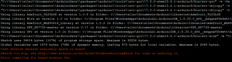
Just as I thought I had obtained the favour of the god of programming, there appeared another vital lesson. Upon the compilation of the code, I got an error message showing that I have exceeded the available space on the board. After checking the link provided, I decided to comment out some libraries. The only scapegoat I found was the library of the 'Time of Flight' and all its associated codes. The error message is depicted in the picture below.
After consulting the expertise of my Instructor, we figured two possibilities in solving this problem. One is to look for a library that uses the memory space minimally. The second option is to use a microcontroller (ATMEGA1284P) with a huge memory space instead of the initial ATMEGA328P. After considering the facts that I had to comment out the library for the Time of Flight (ToF) sensor, and the inevitable possibility that I might still be using more libraries, I decided to use the second option instead. The only thing is that the cost of the ATMEGA1284P is 5,81 Euro. This means a slight increase in the overall cost of the project. the data sheet of the ATMEGA1284P can be found Here.
The video of the display can be found below.
PCB Milling Attempt
In order to mill the PCB board designed for the project, I used the method used for Electronic Production assignment.
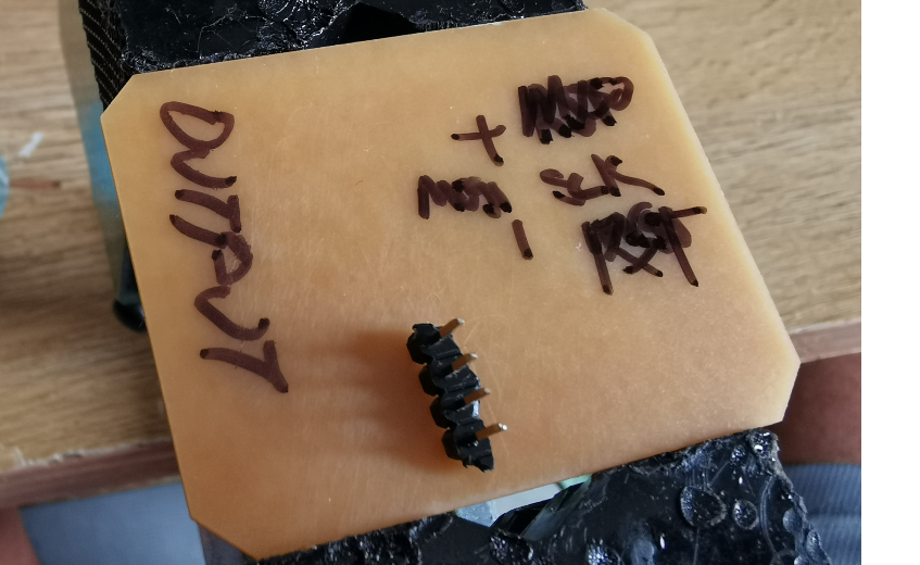
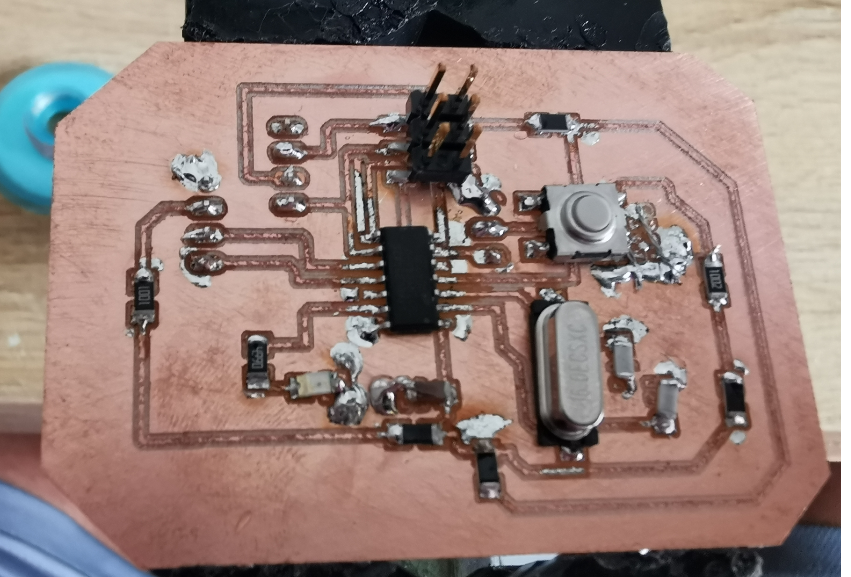
The truth of the matter is, I tried to mill the PCB. Which I managed to mill succe. However, I encountered some problems during the soldering. Still soldering like an amateur. You can find a picture of the first soldering attempt below.
After theunsuccessful attempt. I decided to wait till we purchase our Roland SRM-20 CNC machine. So I will definitely update this as soon as the machine arrives.
You can download the Schematic of the electronic board HERE, or go to the download section of this page.
You can follow the progress of the Final project HERE.