Group Assignment: Output devices
Measure the power consumption of an output device
This week is about measuring the power consumption of an output device. In theory this involves placing an ammeter in series with the device while simultaneously measuring the potential difference across the device.
Current draw of a servo motor
We decided to work with a small servo motor attached to the board described in group assignment 07. The motor can be seen at the back of the image below. A simple program was uploaded to the microcontroller, which just moved the motor back and forth through 15 degrees. The goal was to see the start-up current of the motor as often as possible.

The voltmeter in the background was used to measure the potential difference across the servo power pins. It should have been easy to just connect the ammeter pins of the multimeter in series into the servo motor line, but for some reason that never did come clear, the current simply wouldn’t flow through the ammeter, and so the servo wouldn’t move.
To fix the problem, we instead put a 1Ω resistor in series into the servo connection (as seen in the lower right part of the picture above, between the two banana connectors) and used an oscilloscope to measure the voltage across the resistor. Ohm’s law then conveniently provided us with the current flowing into the servo motor.
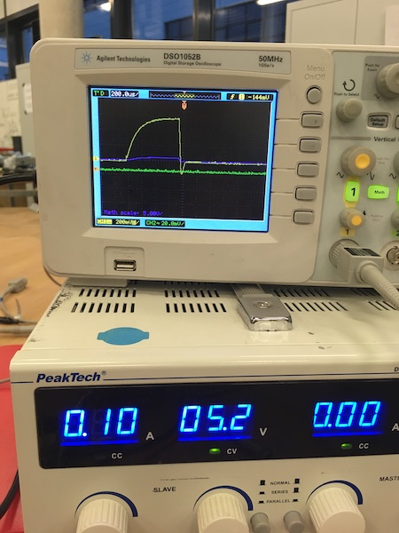
The power supply was beefy enough that the voltage never varied. 5.2V was always supplied, regardless of the state of acceleration of the motor.
The current on the other hand was very much a function of time, as can be seen in the image below. As the control signal caused the motor to accelerate, the current quickly increased, then stabilised at about 560mV as the motor reached constant velocity.

Applying Ohm’s law, we get:
The total power consumed by the motor while it was operating at constant velocity was therefore:
This is not an insignificant amount of power, and sure does provide an order of magnitude to plan around when designing the power supply for our robotic machines.