Group Assignment: Electronics_Design
Use the test equipment in your lab to observe the operation of a microcontroller circuit board (in minimum, check operating voltage on the board with multimeter or voltmeter and use oscilloscope to check noise of operating voltage and interpret a data signal)
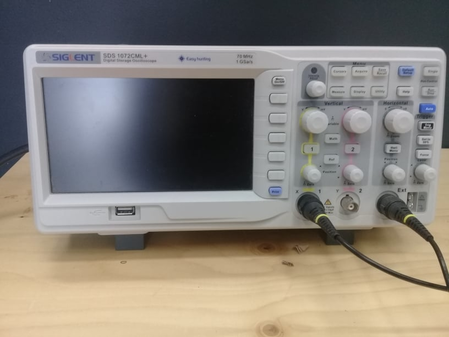
For the group project this week, we used the test equipment in our lab to observe the operation of a microcontroller circuit board. The oscilloscope we used for this group assignment is Siglent's SDS1072CML+.
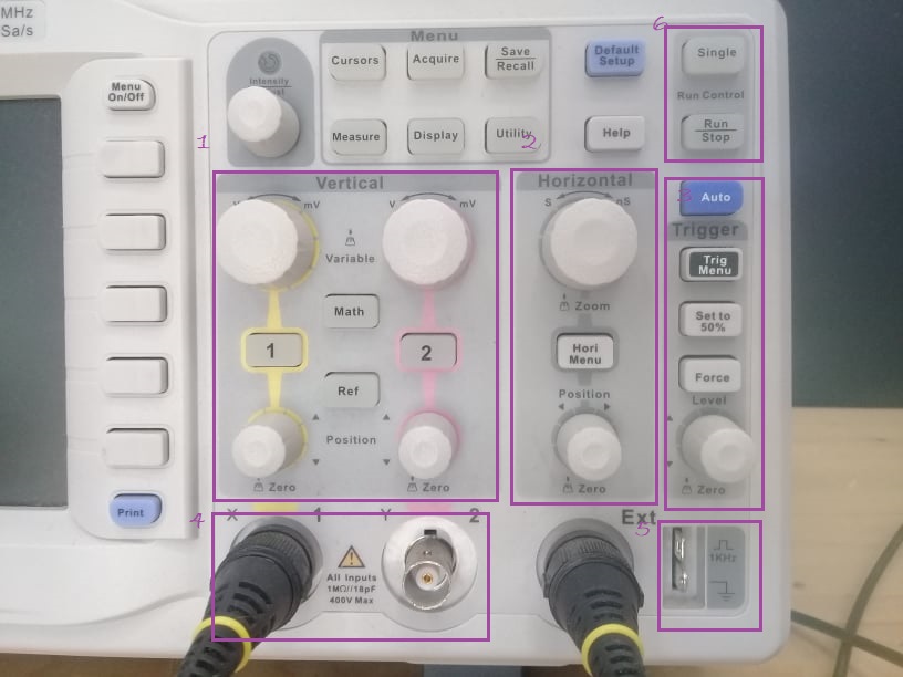
I’ll explain how to use an oscilloscope:
Once the machine is turned on, you can calibrate the machine automatically by first pressing the "Default" button to restore all the settings to its default configuration. Then, plug in a probe into a channel BNC connector on the front panel of the oscilloscope and attach the alligator clips to the Ground Terminal. Finally, click the "Auto Setup" button in the top right corner. In addition, make sure the switch on the probe is also set to 10X.
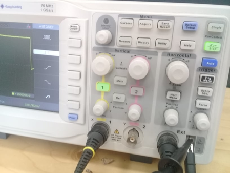
We decided to measure the operation of the onboard LED on an Arduino running a simple Blink code. The setting of one of the board's pins to HIGH was accompanied with the onboard LED being set to HIGH. We probed the pin being set to HIGH but if we really wanted to, we could have probed the onboard LED directly.
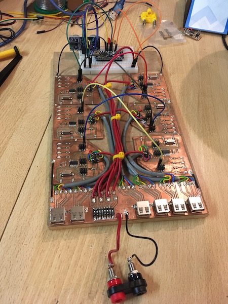
For another test we decided to use one of the simple AtTiny84 boards which we designed to run a pair of servo motors. The board was designed starting with the pinout for the AtTiny:
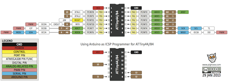
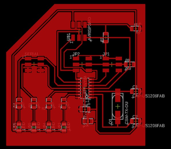
The board was designed with an external crystal, four LEDs which would light when the microcontroller pin went low, and a set of ISP headers. There is a pull-up resistor between RST and Vcc, and several zero-ohm jumpers were included to deal with the challenges of routing the traces. The schematic and board layout are as follows:
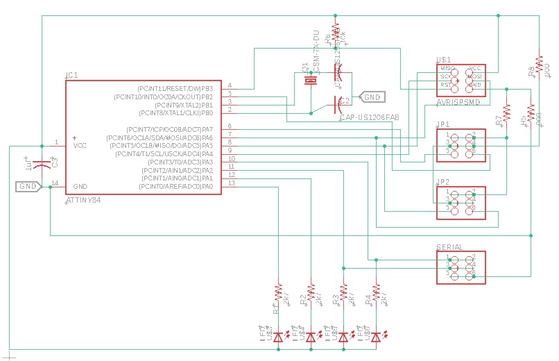
The updated Eagle files are here: SCH/BRD
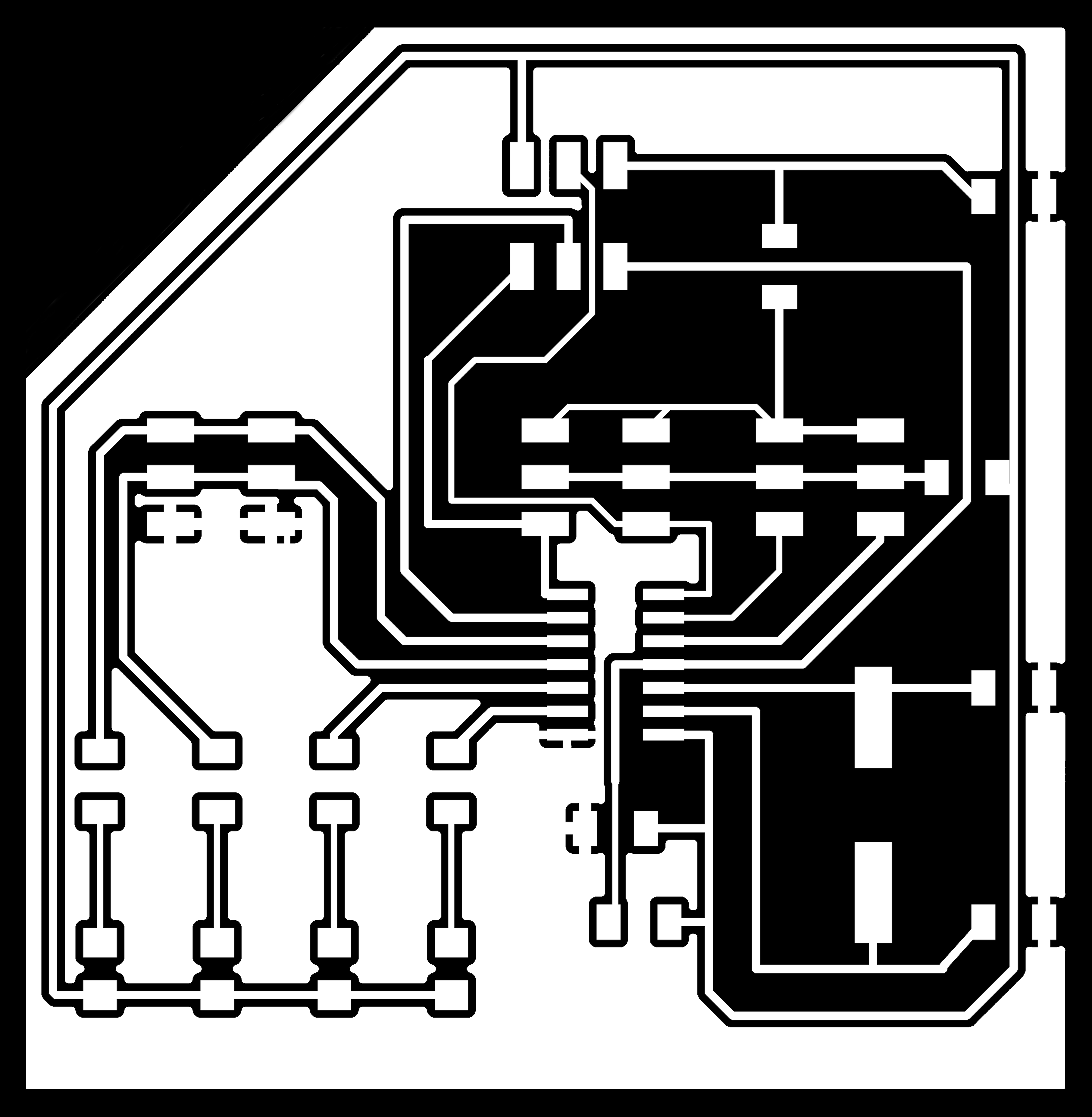
The cleaned up PNGs look like this:

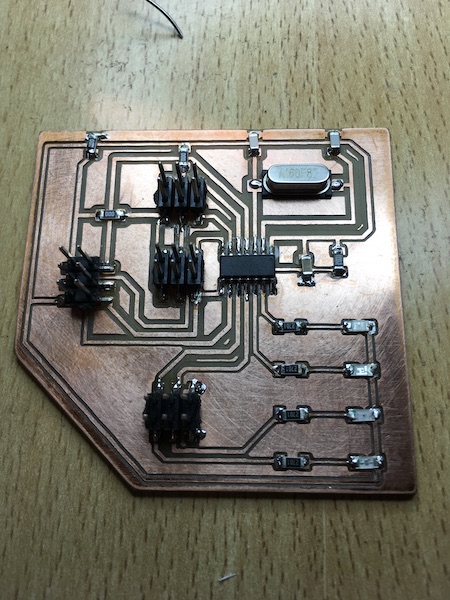
After milling on the Genmitsu, a quick clean-up with emory paper, and careful stuffing, the board looks like this:
The board we’re going to test was part of the six-legged final project robot made by one of our team-members for his final project. Our test board is the one at the bottom left of this image.
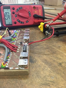
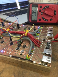
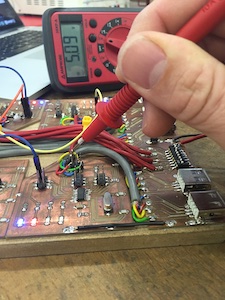
Operating Voltage
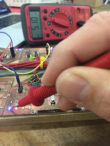
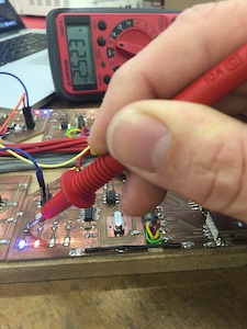
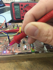
We used a multimeter set on “Volts DC” to measure the voltages at several places around the robot and board. The series of pictures show the voltage at the various positions (source plug, power to PCB, power on the FTDI header, at the Vcc side of the blue LED, at the bottom of the LED/top of the series resistor, and at the bottom of the resistor/output from the microprocessor pin)
To view the noise on the operating voltage signal, we used a digital oscilloscope. The operating voltage was supplied by a desktop power supply and was very clean, as can be seen in the video below.
We used the same oscilloscope on the PWM output line from the microcontroller. The program running on the AtTiny moves the servo back and forth in response to a high or low on the pin connected to the blue LED. The servo is controlled with a PWM signal, which can be observed on the oscilloscope display in the background of the video below.
The PWM spikes are 1.2 divisions apart, with each division equal to 20ms, so the spikes are coming at a rate of 1 per 24ms or 42Hz. The spikes are approximately 0.15 divisions long, but that measurement isn’t useful, as the expected length according to the datasheet is between 1 and 2 ms, so I’ll have to do the measurement again with a higher time resolution setting.