'Teeth without gaps chew the meat.'
African Proverbs
Networking Communication
What is Networking?
Networking is the existence of common communication protocols over digital interconnections for the purpose of transporting and sharing data between nodes a shared medium. The interconnections between nodes and components are formed from a broad spectrum of telecommunication network technologies, based on physically wired, optical, and wireless radio-frequency methods, and other networking hardware. In a nutshell, communications refers to the transmission of this digital data between two or more computers and a computer network or data network is a telecommunications network that allows computers to exchange data. The physical connection between networked computing devices is established using either cable media or wireless media.
Communication Platforms
I2C Bus
I2C, which represents (Inter.Integrated Circuit), is a synchronous, multi-master, multi-slave, packet switched, single-ended, serial computer bus, widely used for attaching lower-speed peripheral ICs to processors and microcontrollers in short-distance, intra-board communication (Reference). All I2C-bus compatible devices incorporate an on-chip interface which allows them to communicate directly with each other via the I2C-bus. This design concept solves the many interfacing problems encountered when designing digital control circuits. Here are some of the features of the I2C-bus:
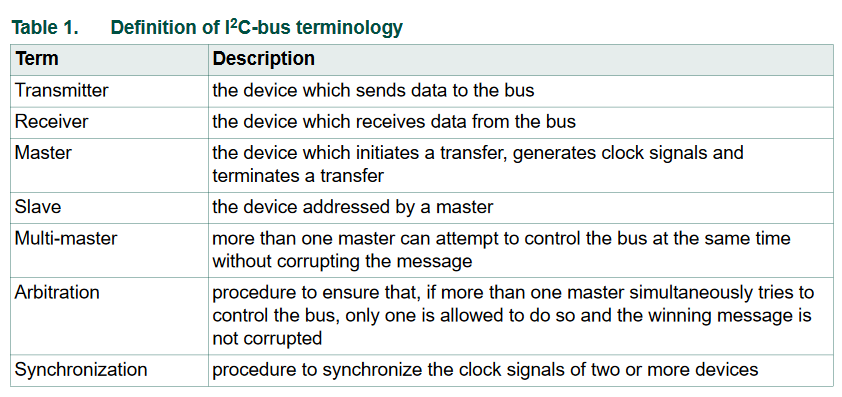
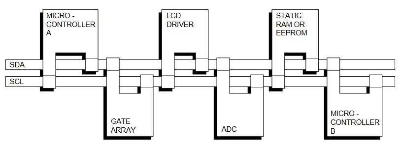
In I2C, two wires, serial data (SDA) and serial clock (SCL), carry information between the devices connected to the bus. Each device is recognized by a unique address (whether it is a microcontroller, LCD driver, memory or keyboard interface) and can operate as either a transmitter or receiver, depending on the function of the device. The transmitters and receivers, devices can also be considered as masters or slaves when performing data transfers. A master is the device which initiates a data transfer on the bus and generates the clock signals to permit that transfer. At that time, any device addressed is considered a slave.
Detailed information about I2C, which includes the benefits of this communication bus, can be found at HERE.
Serial Peripheral Interface (SPI)
The Serial Peripheral Interface (SPI) is a synchronous serial communication interface specification used for short-distance communication, primarily in embedded systems (Reference). SPI devices communicate in full duplex mode using a master-slave architecture with a single master. The master device originates the frame for reading and writing. Multiple slave-devices are supported through selection with individual slave select (SS), sometimes called chip select (CS), lines. The SPI allows high-speed synchronous data transfer between the AVR and peripheral devices or between several AVR devices. On most parts the SPI has a second purpose where it is used for InSystem Programming (ISP).
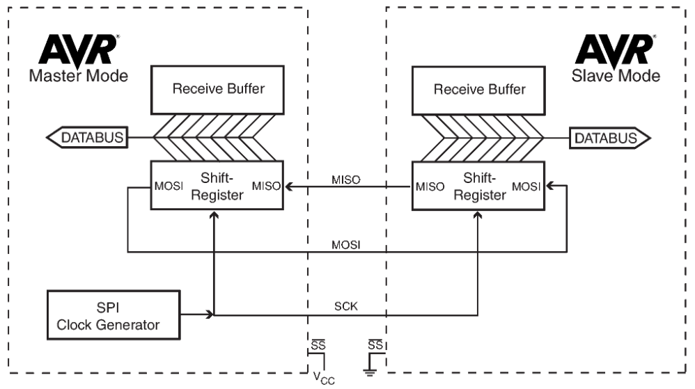
The interconnection between two SPI devices always happens between a master device and a slave device. The mode the AVR is running in is specifiedby the settings of the master bit (MSTR) in the SPI control register (SPCR). The master is the active part in this system and has to provide the clock signal a serial data transmissionis based on. The slave is not capable of generating the clock signal and thus can not get active on itsown. The slave just sends and receives data, if the master generates the necessary clock signal. Themaster, however, generates the clock signal only while sending data. That means the master has to senddata to the slave to read data from the slave.
The SPI consists of four different signal lines. These lines are the shift clock (SCK), the Master Out SlaveIn line (MOSI), the Master In Slave Out line (MISO) and the active low Slave Select line (SS). When theSPI is enabled, the data direction of the MOSI, MISO, SCK, and SS pins are overridden as depicted in the table below.
p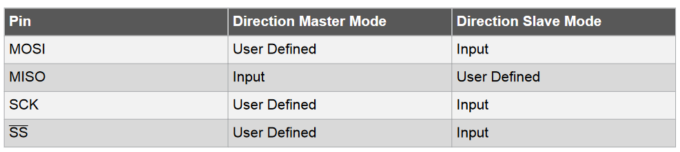
This table shows that the input pins are automatically configured. The output pins must be initialized manually by the software. The reason for this is to avoid damages through driver contention.
Detailed information about SPI can be found at HERE.
Universal Serial Bus (USB)
Universal Serial Bus (USB) is an industry standard that establishes specifications for cables and connectors and protocols for connection, communication and power supply (interfacing) between computers, peripherals and other computers. USB was designed to standardize the connection of peripherals to personal computers, both to communicate with and to supply electric power.
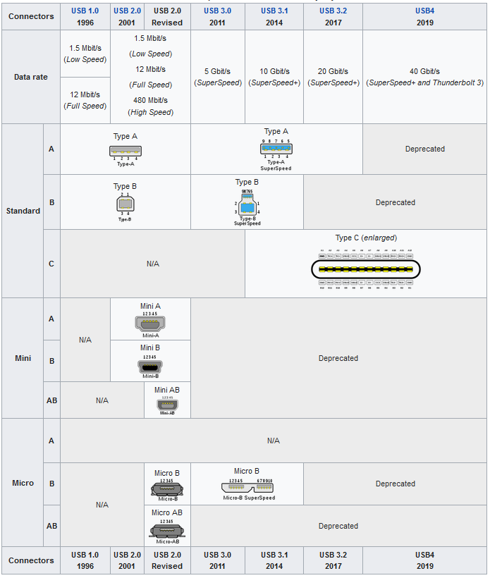
USB connection is widely used by different devices as the ideal communication link because it was designed to be more robust than most past connectors, and due to its durability (hot swappable) and compatibility. The devices that uses USB include computer keyboards and mice, video cameras, printers, portable media players, disk drives and network adapters. In addition, USB connectors have been increasingly replacing other types as charging cables of portable devices.
You can access the assignment HERE.
You can follow the progress of the Final project HERE.