Computer-Controlled Machining
Intro
I think this was one of the hardest weeks for me, and the reason I didn’t complete it in the assigned week.
To begin with, the amount of wood working jargon I had never heard was bewildering. I had to ask AI to write me a Glossary just to start to understand what was going on and required.
My skills at CAD were still improving, but my gut feeling told me that a code approach was the way I wanted to move forward with this, for 2 main reasons:
- I’m way more comfortable with code than following a procedural approach to designing something in a GUI
- eventually AIs would get good at code for CAD too
The last point turned out to be true. My first attempts at using several AIs to write me OpenSCAD code were quite disappointing, and the reason I decided to learn the language properly. They did point me in the right direction, and gave a glimpse of what could be possible.
Fast-forward a few months of AI improvement at breakneck speed, and using AI agents with frontier models is reaching human level capabilities.
Several benchmarks like benchcad or cadbenchmarks are already tracking the improvements in the field. Specialized sites like Adam are tailored to this CAD with AI.
Some AI solutions write code to be rendered by a CAD software, others drive a particular CAD software through a MCP connector, and some systems even bypass the CAD software altogether and hand the user the final step or stl file !
Since I didn’t want to focus on one particular CAD software, but still wanted to retain an understanding of what’s actually being built, I opted for the first approach and use code to describe my desired intents.
An additional point of friction was that operating the CNC at our lab requires a post processor that was only made available for Fusion 360, which has no native binary for Linux. While I tried to use the web version, it did not allow all the things I needed, namely importing extra tools that I needed.
Eventually I caved in and had to boot into a Windows to run Fusion 360. This is a disappointing outcome for a hardcore Linux user as I am ! 🐧😝
This document covers the parametric “CAD with Code” design exploration, the iterative engineering refinements, and the subsequent Autodesk Fusion 360 CAM preparation for milling the motorized Arch structure on the Ouplan Steel 3020 ATC CNC router at FabLab Benfica, plus some bonus from addictive manufacturing at the end, to make a complete object.
1. Parametric Design (“CAD with Code”)
Before moving into Fusion 360 for CAM toolpath generation, I designed the entire assembly parametrically using code, evaluating several programmatic CAD frameworks in parallel and ultimately exporting the final arch.step file from build123d and then in RepliCad.
For transparency, the full extracted prompt-by-prompt transcript and Git commit history can be found in cad_with_code_conversations.md.
This was done in Google’s AntiGravity IDE, using Google’s models.
Initial Main Prompt
“I want to evaluate a few code approaches to CAD. Please design an arch (half a circle) with 1 meter inner diameter and 1 meter plus 8 cm outer diameter. The thickness should be 16 mm. On both ends of the arch, a small protuberance of 16 mm deep should extend, that will serve as a joinery into another piece. This arch is meant to be cut in a CNC machine. Please generate different outputs in openscad, freecad python, cadquery, build123 and cascade studio”
I rendered the results in all the frameworks and since it sounded promising, I proceeded to add more changes.
Major Iterative Changes Requested
- 6 mm CNC Dogbone Reliefs (
fixed dogbones): Added dogbone fillets for a6 mmend mill (r = 3 mm) at all internal joinery corners, later refined so each relief circle’s center is offset at \(45^\circ\) by \(r / \sqrt{2}\) (~2.12 mm), making the circle perimeter tangent to the corner vertex rather than centered directly on the corner. - 3-Sided Wheeled Support Boxes (
arhes with boxes): Added two 3-sided support boxes (each composed of 1 top plate and 2 side plates, leaving the bottom and ends open) that receive the arch tenons on top and leave a30 mminner gap to house25 mmwide,100 mmdiameter 3D-printed wheels. - Wheel Positioning & Ground Clearance (
added wheels fitings): Added axle holes for two sequential100 mmdiameter wheels inside each box and shifted the axle centers closer to the bottom edge so the wheels clear the underside of the top plate (5.5 mminternal top clearance) while providing18 mmof rolling clearance beneath the box walls. - Parametric Press-Fit Kerf Compensation (
added kerf): Introduced a globalkerf = 0.1 mmvariable across all scripts, expanding external male tabs/fingers by+kerfand shrinking internal female slots by-kerffor tight press-fit assembly. - NEMA 17 Stepper Motor Mounts (
added nema 17 fittings): Replaced one driven wheel’s simple axle hole on the outer side panel of each box with a standard NEMA 17 mounting pattern (4× Ø3.2 mmM3 bolt holes spaced on a31 mmsquare pitch around the central shaft bore). - Custom 3D-Printed Shaft Sleeve (
enlarged shaft wholes to acomodate a sleeve): Because a24 mmNEMA 17 shaft passing through a thick wooden wall left too little engagement inside a25 mmwide wheel hub, all driven and passive wheel axle holes across both inner and outer panels were enlarged toØ12 mmto accommodate a custom 3D-printed shaft extender sleeve. - Material Thickness Adaptation (
adapted material thickness to 12.5 mm→reduced material thickness to 12 mm): After measuring the actual sheet stock with calipers, updated the globalthicknessparameter (and all dependent tab depths, slot widths, and box widths) first from16 mmto12.5 mm, and finally to12.0 mm. - Flat 2D CNC Layout, Symmetry Fixes & STEP Export (
lay out on a plane and adjust some positions): Removed the visual-aid wheels, laid all 7 structural parts flat on the \(XY\) plane (\(Z \in [0, 12]\text{ mm}\)), centered the arch slots, extended side slot cuts past the plate edges to eliminate thin coplanar boolean slivers, made all fingers and wheel axles symmetric, and addedexport_step(assembly, "arch.step")toarch_build123d.py. - Adding RepliCad (JS & TS) and Fixing Cascade Studio: Added
arch_replicad.jsand a strongly typedarch_replicad.tsimplementation for the RepliCad Workbench, and updatedarch_cascade.jsto work with thezalo/CascadeStudioweb runner. - Doubling Box Length (
200 mm→400 mm) & Final Nesting Optimization: Doubled the length of both support boxes from200 mmto400 mmfor greater stability (moving the wheels and finger joints from \(\pm 68\text{ mm}\) to \(\pm 168\text{ mm}\) to preserve the edge distance) and re-nested all 6 box plates inside the500 mminner radius of the arch with at least20 mmclearance between all parts.
CAD-with-Code Frameworks Comparison
- OpenSCAD (
arch.scad): Uses a declarative Constructive Solid Geometry (CSG) language built around 2D primitives (circle,square) combined viaunion()anddifference()and extruded withlinear_extrude(). It is very fast to write and preview for 2.5D CNC parts, but it represents geometry as polygonal meshes (controlled by$fn) rather than true analytical curves and cannot natively export B-RepSTEPfiles for Fusion 360 CAM. Although I was not planning to use this format for manufacturing, the language was the one I was most comfortable with, and served as the basis for comparing to other formats. - FreeCAD Python (
arch_freecad.py): Drives FreeCAD’s internal OpenCASCADE (Part) kernel imperatively by instantiating 3D solids (Part.makeBox,Part.makeCylinder), mutating their positions withtranslate(App.Vector(...)), and chaining.fuse()and.cut()operations into document features. It provides full native B-Rep precision and direct integration with the FreeCAD GUI, though the script is comparatively verbose because every primitive and boolean cut is constructed and positioned manually in 3D space. I had high hopes for this, because I had tried it once, but it proved cumbersome to work with, because I had to delete everything and import another macro for every iteration. I quickly abandoned rendering in FreeCAD. - CadQuery (
arch_cadquery.py): A fluent Python library built on OpenCASCADE (OCP) that uses a 2D sketch-and-workplane paradigm (cq.Sketch().rect().circle(..., mode="subtract")placed oncq.Workplane("XY").extrude()). Its method-chaining syntax mirrors how mechanical engineers sketch in parametric CAD tools like Fusion 360 or SolidWorks, and it supports named, color-coded assemblies (cq.Assembly) and nativeSTEPexport. This is the most established one, but although I’m comfortable with the method chaining, it’s not very pythonic. - build123d (
arch_build123d.py): A modern Python CAD framework (also built on OpenCASCADE/OCP) that replaces long method chains with clean Pythonic context managers (with BuildPart():,with BuildSketch():,with Locations(...):) and explicit boolean modes (Mode.SUBTRACT). It proved to be the cleanest, most readable, and most maintainable python script in the repository, serving as the “source of truth” to generate the finalarch.stepfile viaexport_step(). The exporting was easy, and this is what I used initially for the Step generation. - Cascade Studio (
arch_cascade.js): A browser-based JavaScript environment wrapping OpenCASCADE Compiled to WebAssembly (opencascade.js) using functional CSG calls (Box(),Cylinder(),Union(),Difference(),Translate()). While convenient for zero-install web sharing, its in-browser parser has quirks with modern ES6 syntax, top-level return statements, and coplanar boolean faces (requiring0.1 mmoverlaps to avoid kernel errors). Despite the quirks, this was actually quite interesting as I find JavaScript more readable and it also transpiles OpenSCAD files. - RepliCad (
arch_replicad.js/arch_replicad.ts): A modern JavaScript/TypeScript library running OpenCASCADE in WebAssembly in the browser (RepliCad Workbench), offering a fluent object-oriented API (shape.fuse(),shape.cut(),shape.translate()) and first-class TypeScript type definitions (Solid,Shape). It provides a much cleaner developer experience than Cascade Studio and exportsSTEP/STLdirectly from the browser. This ended being my choice once I discovered it, as I find the strong typing of TypeScript clearer than the loosely typed JavaScript.
I’m not entirely sure which I would pick for further development:
- OpenSCAD is not B-Rep, but CascadeStudio could help with this
- FreeCAD python is pretty horrible, so probably not this one
- CadQuery is the most known, but not very pythonic
- Build123d is nicer, but it’s still python, which is not my favorite language
- CascadeStudio is most interesting because it also transpiles OpenSCAD
- RepliCad is not as known, but supports TypeScript, the interface is quite nice, and can be embedded in pages
I’m leaning towards RepliCad.
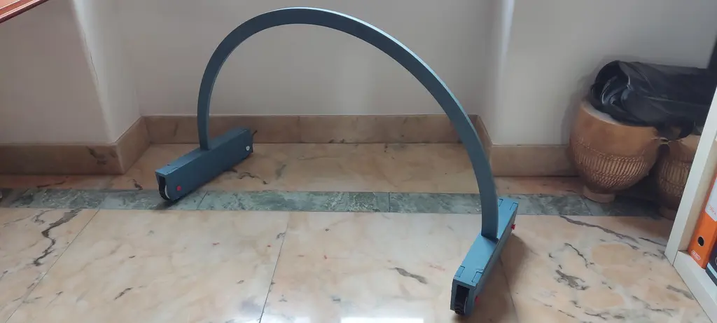
And here’s the result:
2. Preparing the Manufacturing Model & Nesting in Fusion 360
The imported assembly consists of the 7 press-fit components designed for 12 mm stock:
- 1 large semicircular arch (1000 mm inner diameter, 1080 mm outer diameter) with press-fit tenon ends
- 2 box top plates (400 × 55 mm) featuring a central slot for the arch tenon and side slots for the box walls
- 4 box side plates (400 × 100 mm, 2 inner and 2 outer) with finger-joint tabs, Ø12 mm wheel shaft sleeve holes, and (on the 2 outer plates) a NEMA 17 stepper motor mounting pattern (a central Ø12 mm hole surrounded by four Ø3.2 mm screw holes)
All internal press-fit corners include dogbone fillets so the cylindrical end mill can clear the inside corners and allow mating parts with square edges to slot together cleanly.
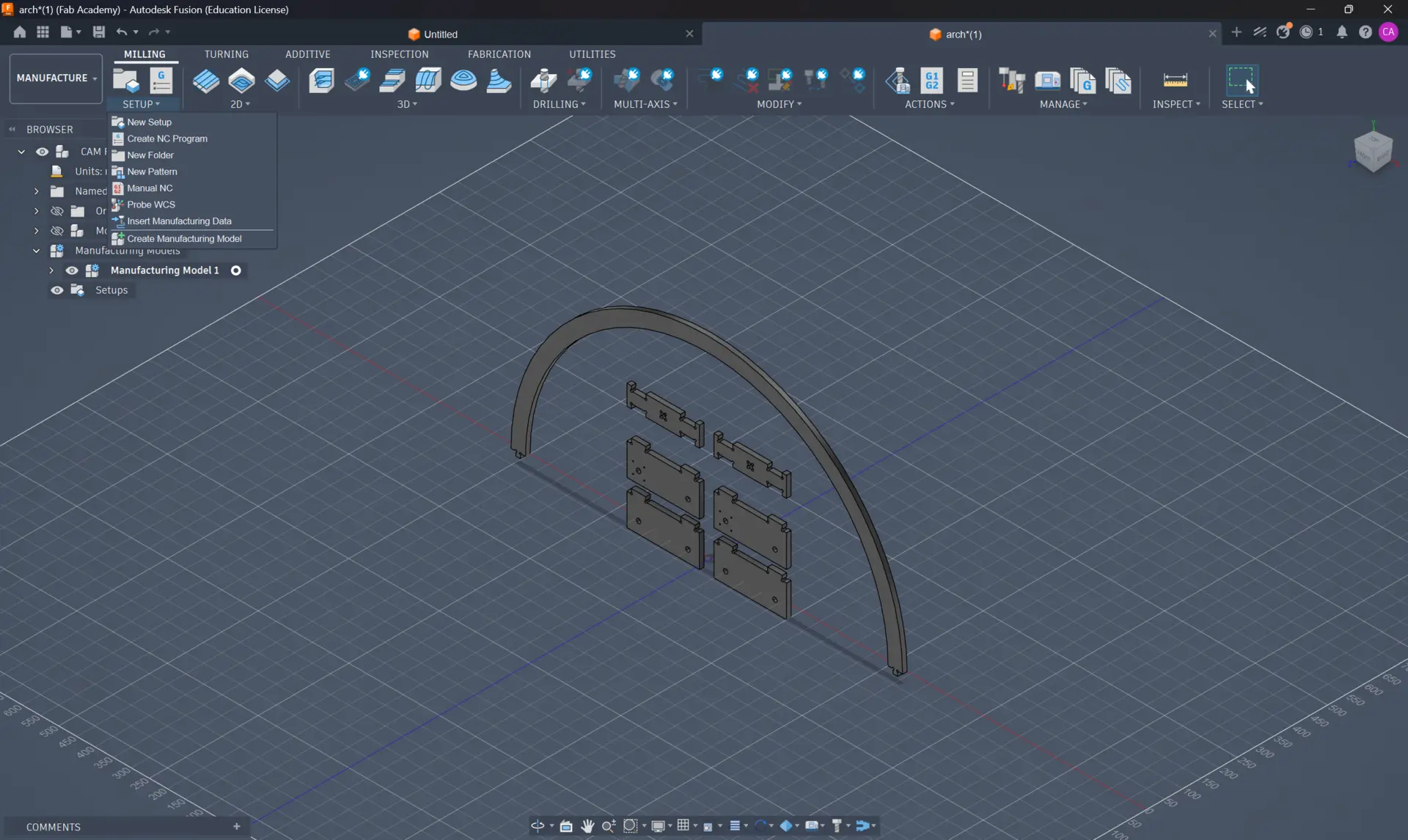
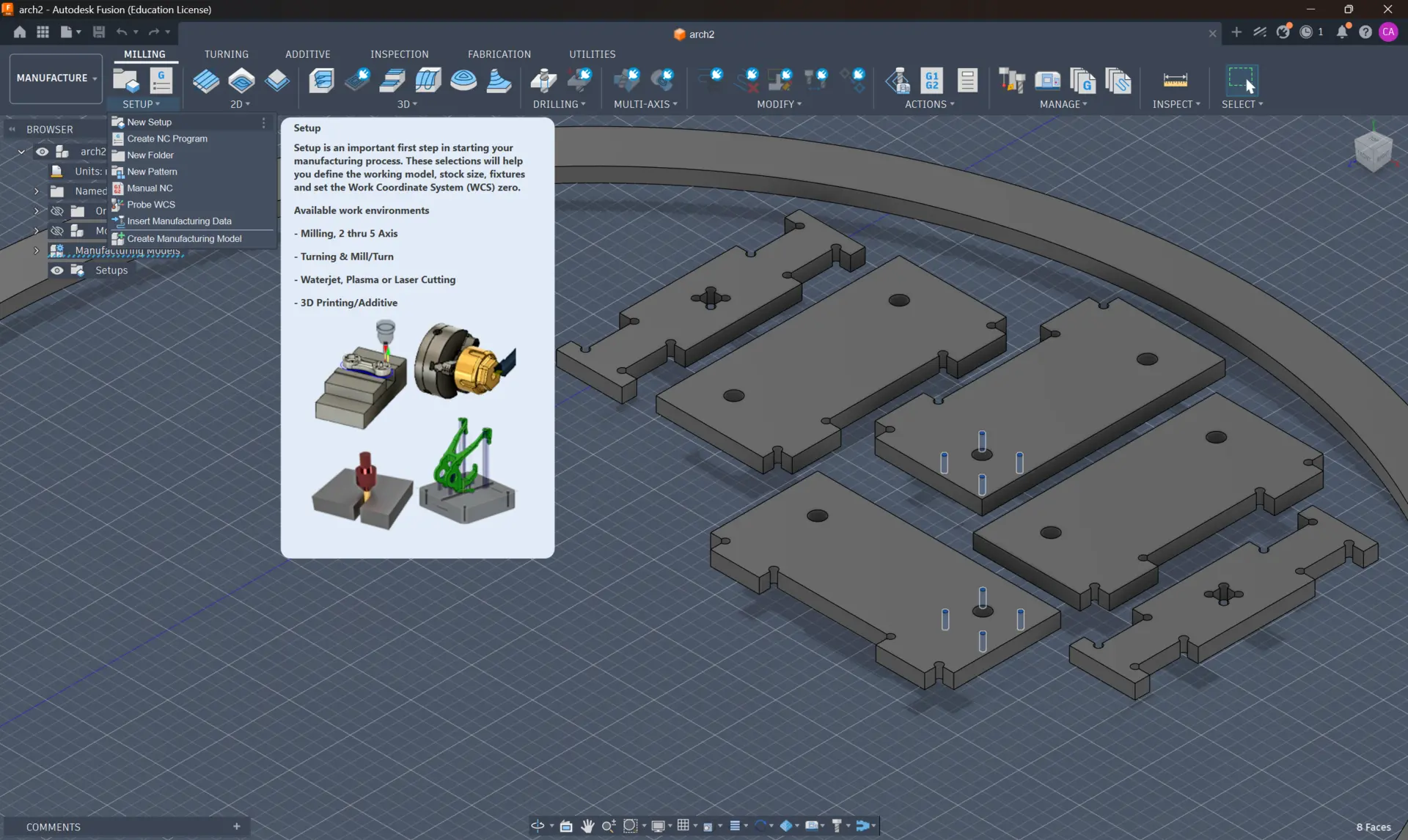
To prepare the 3D assembly for 2D CNC routing without altering the original 3D design assembly, I switched from the Design workspace to the Manufacture workspace and created a dedicated Manufacturing Model via Setup > Create Manufacturing Model:
Inside the Manufacturing Model environment (accessible by right-clicking Manufacturing Model 1 and selecting Edit Manufacturing Model), Fusion provides standard solid modification tools alongside fabrication-specific layout tools under the Modify menu:
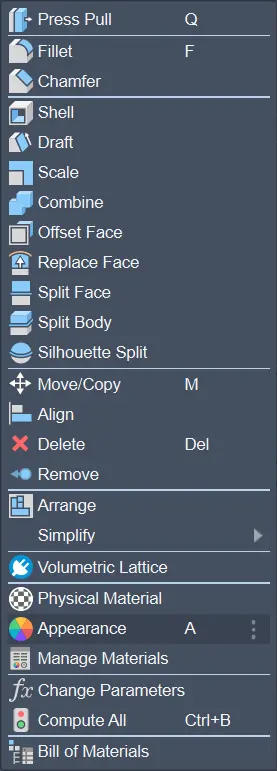
From the Modify menu, I selected Arrange to automatically lay all 3D components flat onto a single 2D plane for sheet stock cutting:
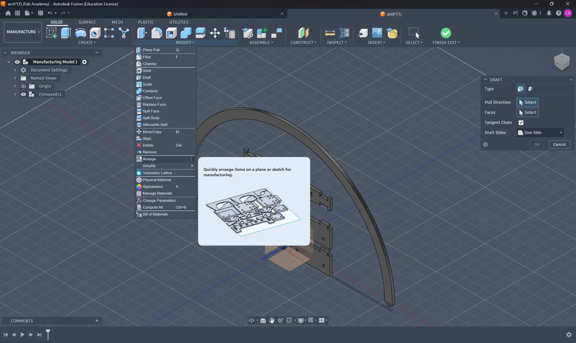
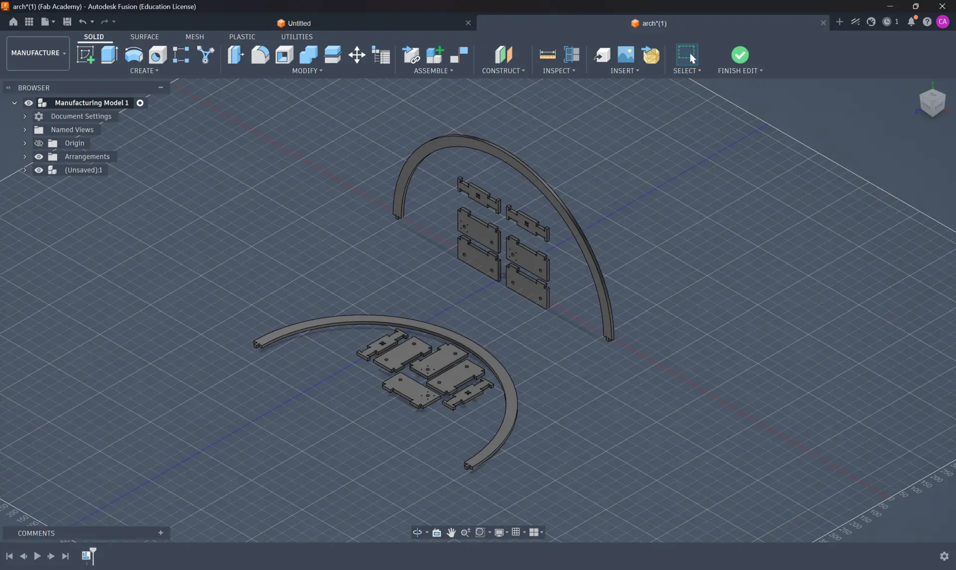
In the Arrange dialog, I selected all 7 components and defined the target plane/envelope. Fusion nested the 6 smaller plates and connector bars neatly inside the inner curve of the semicircular arch, minimizing material waste:
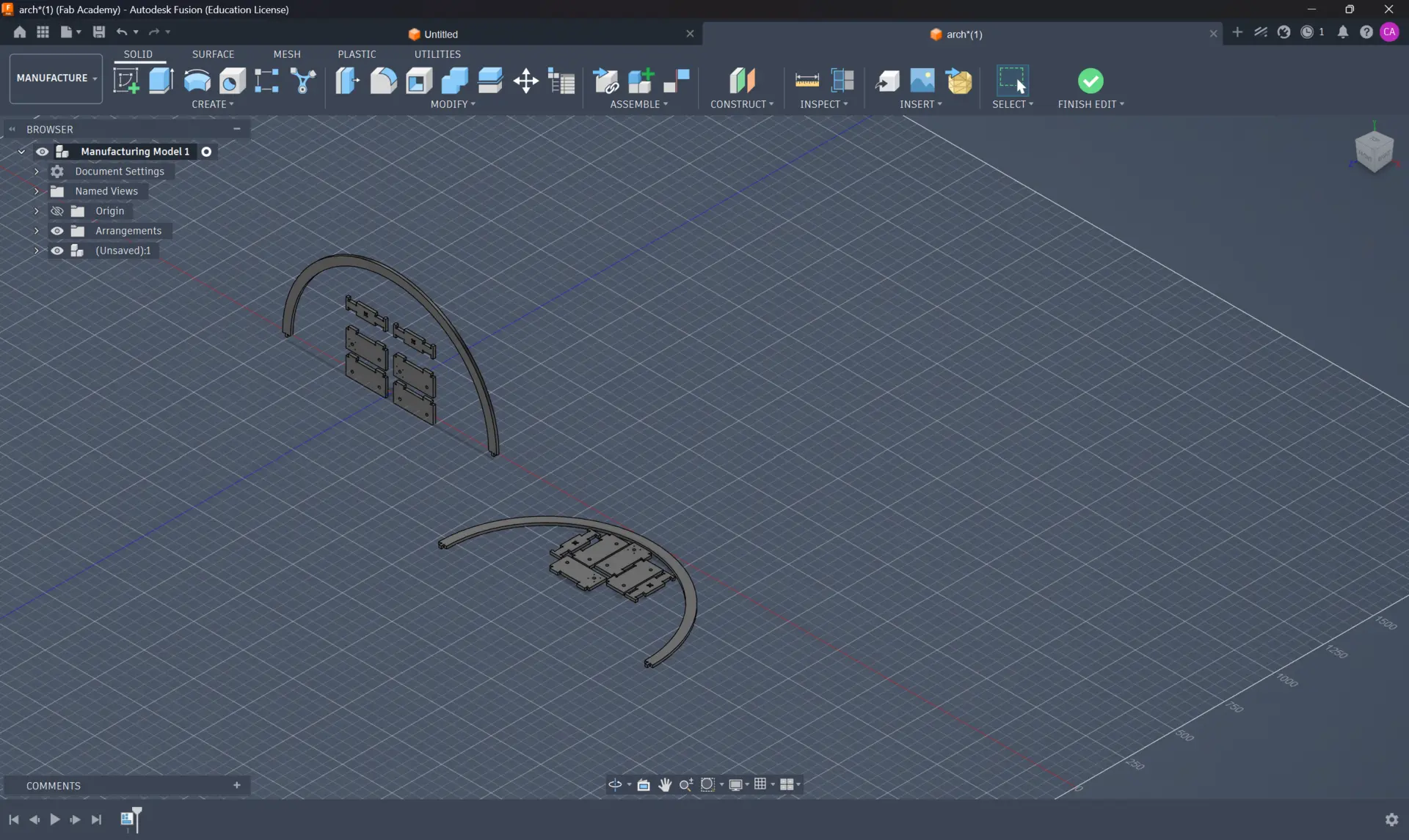
Below is a closer view of the flat arrangement compared to the original upright assembly before clicking Finish Edit (and hiding the original model bodies so only the flat manufacturing model remains active):
3. Configuring the CNC Tool Library
Before creating the machining setup and toolpaths, I needed to load the tool definitions for our lab’s Ouplan Steel 3020 CNC router, which features an Automatic Tool Changer (ATC).
In the Manufacture toolbar, I opened Manage > Tool Library:
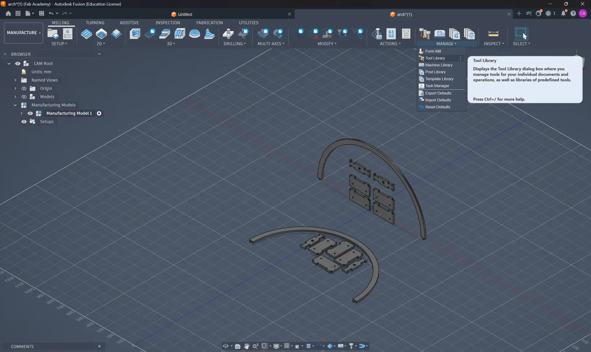
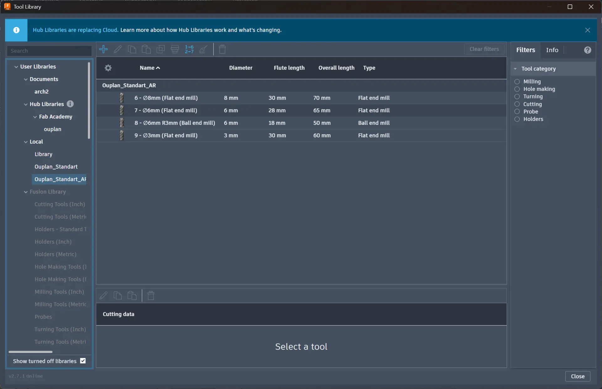
I imported the base Ouplan_Standart library provided by our instructor, André, into the Local library section. Initially, the standard library included three tools in slots 6, 7, and 8:
- Tool 6: Ø8 mm Flat End Mill (Flute length: 30 mm, Overall length: 70 mm)
- Tool 7: Ø6 mm Flat End Mill (Flute length: 22 mm, Overall length: 50 mm)
- Tool 8: Ø6 mm Ball End Mill (Flute length: 18 mm, Overall length: 50 mm)
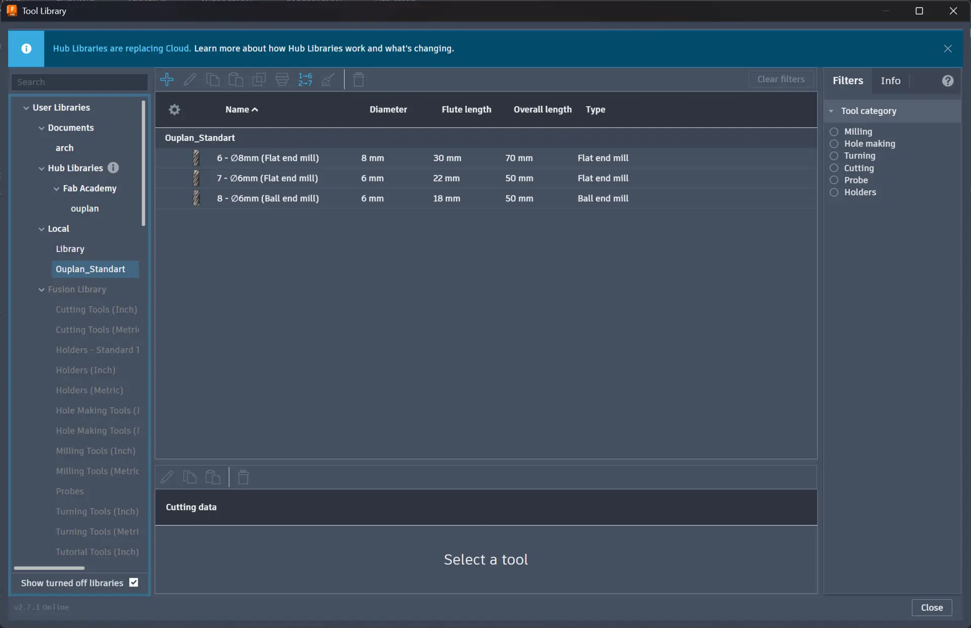
Because two of the mounting plates in my design have small mounting holes around the center bore that are too small for a 6 mm end mill, we updated the library (Ouplan_Standart_AR) to match the exact physical cutters loaded into the ATC magazine and added a 3 mm flat end mill in Tool Slot 9:
| Tool Slot | Description | Diameter | Flute Length | Overall Length | Typical Feeds & Speeds (MDF/Wood) |
|---|---|---|---|---|---|
| Tool 6 | Flat End Mill | 8 mm | 30 mm | 70 mm | 18,000 RPM, 4,000 mm/min cut |
| Tool 7 | Flat End Mill | 6 mm | 28 mm | 65 mm | 18,000 RPM, 4,000 mm/min cut, 600 mm/min plunge |
| Tool 8 | Ball End Mill (R3mm) | 6 mm | 18 mm | 50 mm | — |
| Tool 9 | Flat End Mill | 3 mm | 30 mm | 60 mm | 18,000 RPM, 4,000 mm/min cut, 600 mm/min plunge |
4. Defining the CAM Setup & Stock
With the arranged manufacturing model ready and the tools configured, I selected Setup > New Setup to define the Work Coordinate System (WCS), stock dimensions, and target bodies:
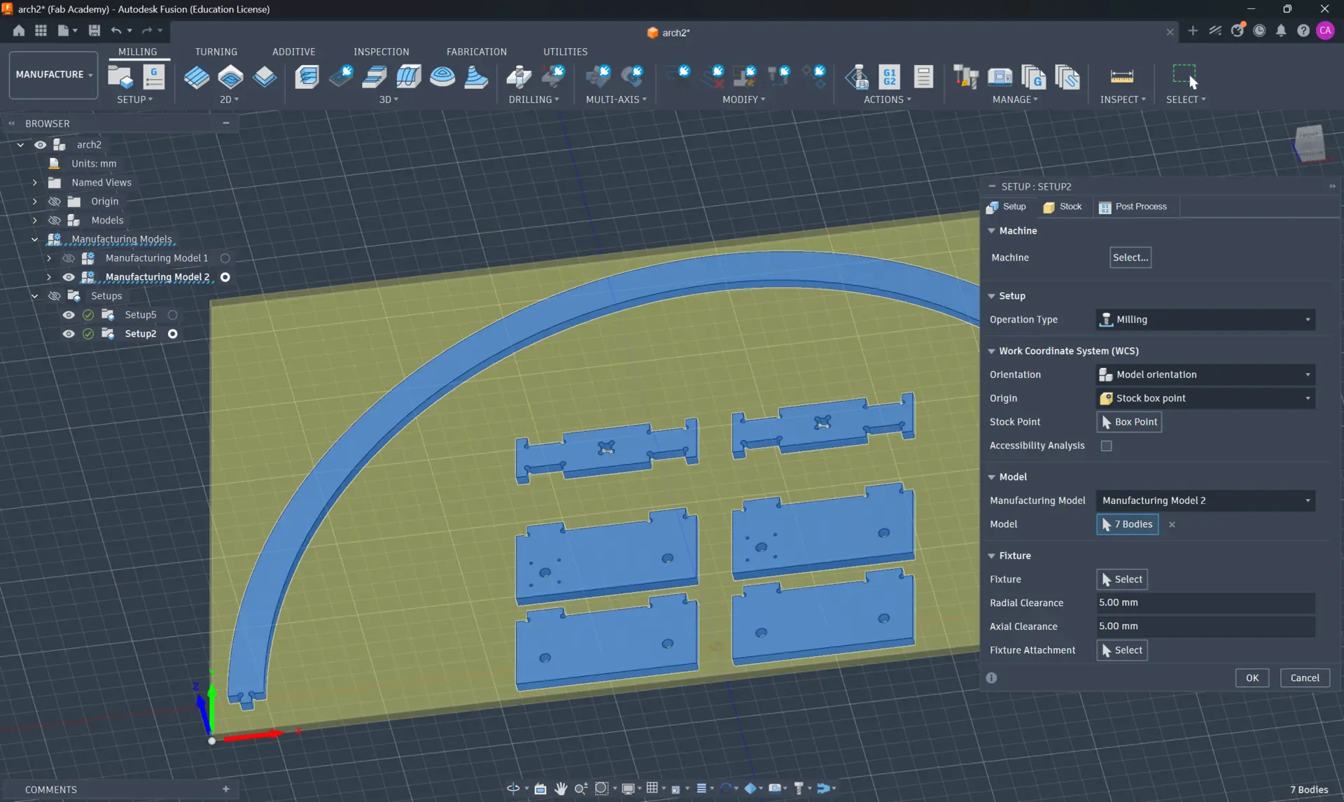
In the Setup tab:
- Operation Type: Milling
- WCS Orientation: Model orientation (with Z pointing up perpendicular to the sheet, and X/Y aligned with the sheet edges)
- WCS Origin: Stock box point set to the front-left corner of the stock, matching how we zero the G54 work origin on the Ouplan CNC bed using Jog mode in InoControl
- Model: Selected all 7 Bodies from the arranged Manufacturing Model
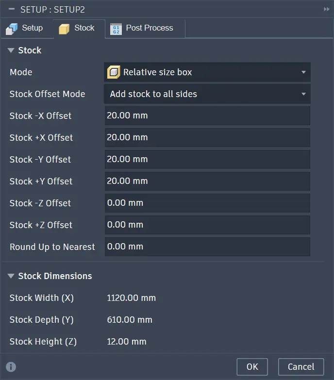
In the Stock tab, I configured the material boundaries:
- Mode: Relative size box
- Stock Offset Mode: Add stock to all sides
- Side Offsets (-X, +X, -Y, +Y): 20.00 mm margin around all sides to leave room for fixturing clamps and tool clearance
- Top/Bottom Offsets (-Z, +Z): 0.00 mm
- Resulting Stock Dimensions: 1120.00 mm (X) × 610.00 mm (Y) × 12.00 mm (Z)
Note: At this point, I showed the whole project to André, who suggested I should make the support boxes longer for greater stability. As such, I went back to code, updated dimensions and exported again through RepliCad, which is why you might notice the dimensions on next screenshots are different. Since all the previous steps would be identical, I did not screenshot those again.
5. Toolpath Generation: Holes, Boring & Contours
It is important to order the CNC operations from smallest internal features to outer profiles so that parts remain rigidly held by the stock while internal holes and pockets are machined:
1. Small internal holes (using Tool 9 — Ø3 mm Flat End Mill)
2. Larger internal holes and cutouts (using Tool 7 — Ø6 mm Flat End Mill)
3. Outer 2D Contours with tabs (using Tool 7 — Ø6 mm Flat End Mill, multiple stepdowns, conventional milling, and holding tabs so cut pieces do not shift or fly out)
Machining the Small Mounting Holes (Tool 9 — Ø3 mm)
First, I targeted the 8 small mounting holes (4 around each central bore on the two red plates) which will take the screws for the NEMA motors. Initially, I tested selecting the 8 cylindrical hole faces using a Drill operation (Order: Shortest distance):
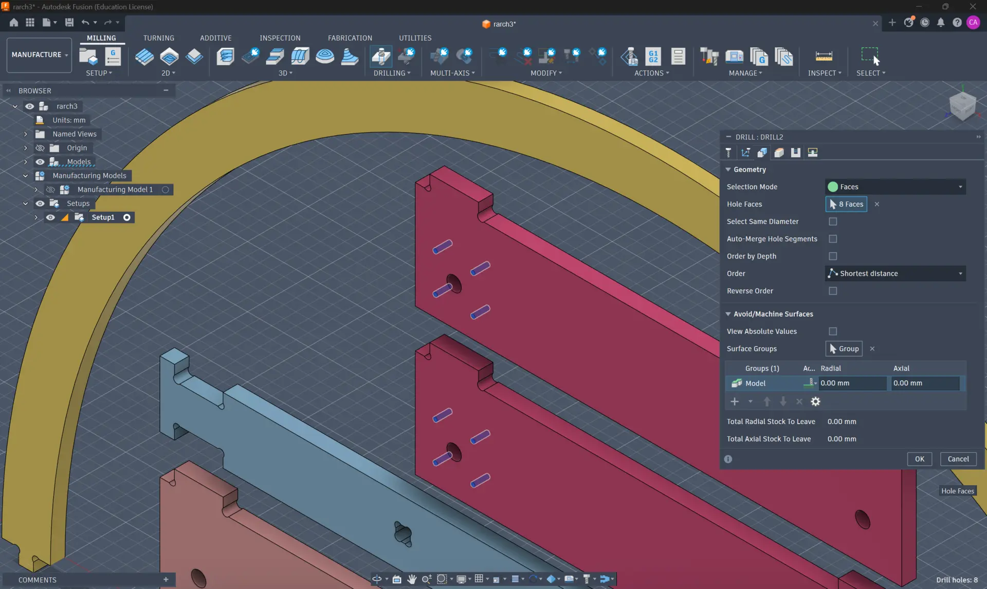
However, since we are using a flat end mill ([T9] Ø3 mm) rather than a twist drill bit, a helical Bore operation provides much better chip evacuation and accuracy for holes slightly larger than the tool diameter.
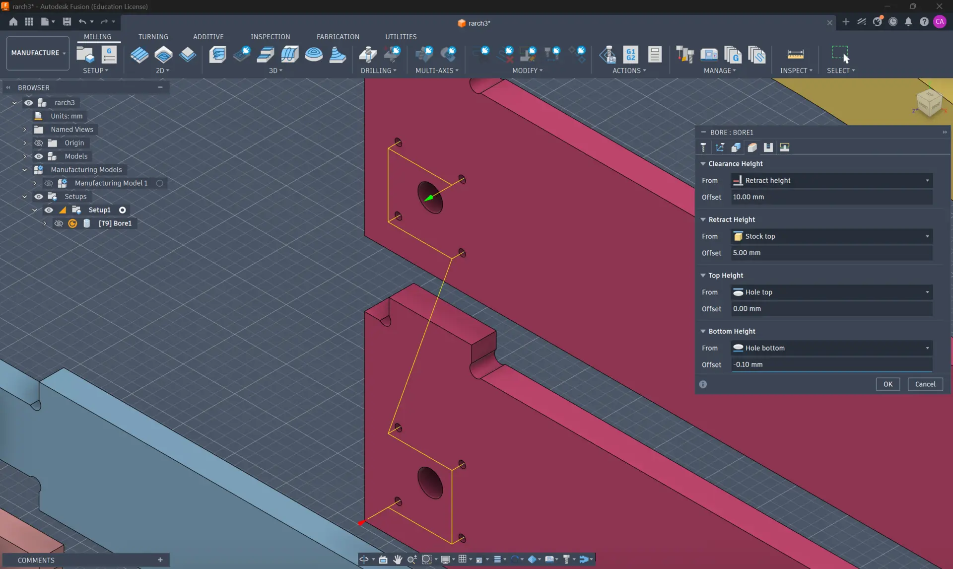
In the Bore operation (BORE1 with Tool T9), I configured the Heights tab to ensure the cutter cleanly breaks through the bottom of the plate:
- Clearance Height: 10.00 mm above Retract height
- Retract Height: 5.00 mm above Stock top
- Top Height: 0.00 mm from Hole top
- Bottom Height: -0.10 mm from Hole bottom (milling 0.1 mm past the bottom face for a clean through-hole) - Note: although this was recommended, André asked to make it 0, as it could slightly damage the bed.
Toolpath Simulation
Before exporting any G-code, I ran the Simulate tool in Fusion 360 to verify the toolpath order, helical ramp motion, and linking retracts, and to check for any collisions.
First simulation testing the [T9] Bore1 operation on the small mounting holes:
Next, I added the second boring operation ([T7] Bore 6mm) using the 6 mm flat end mill (Tool 7) to machine all the larger circular holes across the plates and bars. Because the Ouplan 3020 has an Automatic Tool Changer (ATC), both [T9] Bore 3mm and [T7] Bore 6mm can be grouped in the same setup—the machine automatically swaps from Tool 9 to Tool 7 during the job. Here is the simulation of both operations running sequentially:
Next, I also simulated the contour, but I did not record that one. I any case the real contour can be seen in a video ahead.
6. Post-Processing & Exporting G-Code (.nc)
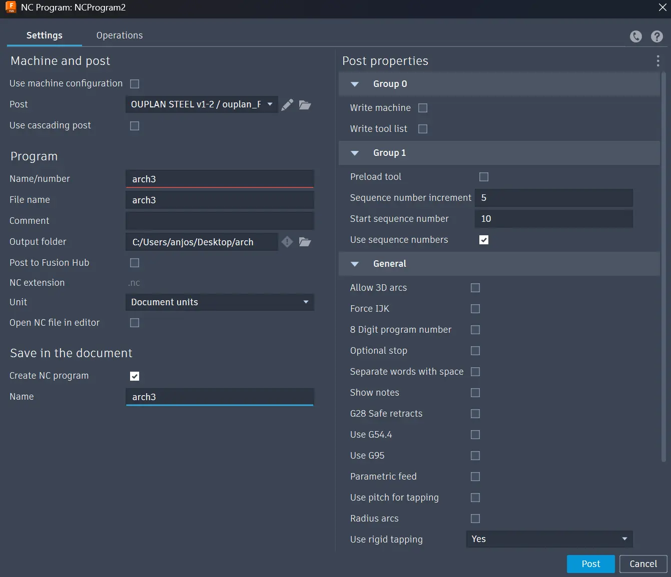
Once all toolpaths were verified in simulation, I generated the machine-specific G-code via Actions > Post Process (or Create NC Program):
- Post-Processor:
OUPLAN STEEL v1-2 / ouplan_F...(the custom post-processor for FabLab Benfica’s Ouplan Steel 3020 controller) - File Name:
arch3.nc - Units:
Document units(mm)
Machine Setup & Milling Workflow on the Ouplan Steel 3020
After exporting arch3.nc to a USB drive, the workflow at the CNC router follows our lab’s standard operating and safety procedures:
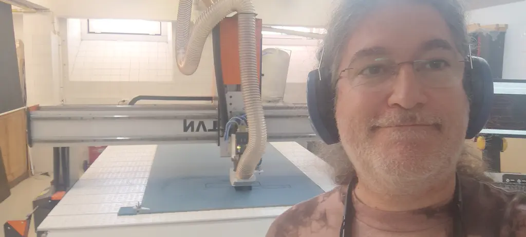
- Safety First: Wear safety glasses, ear protection, and closed-toe shoes; tie back long hair, remove loose items, and never wear gloves while operating the spindle. Keep hands clear of the bed and stay alert (Look, Listen, Smell) near the emergency stop throughout the cut.
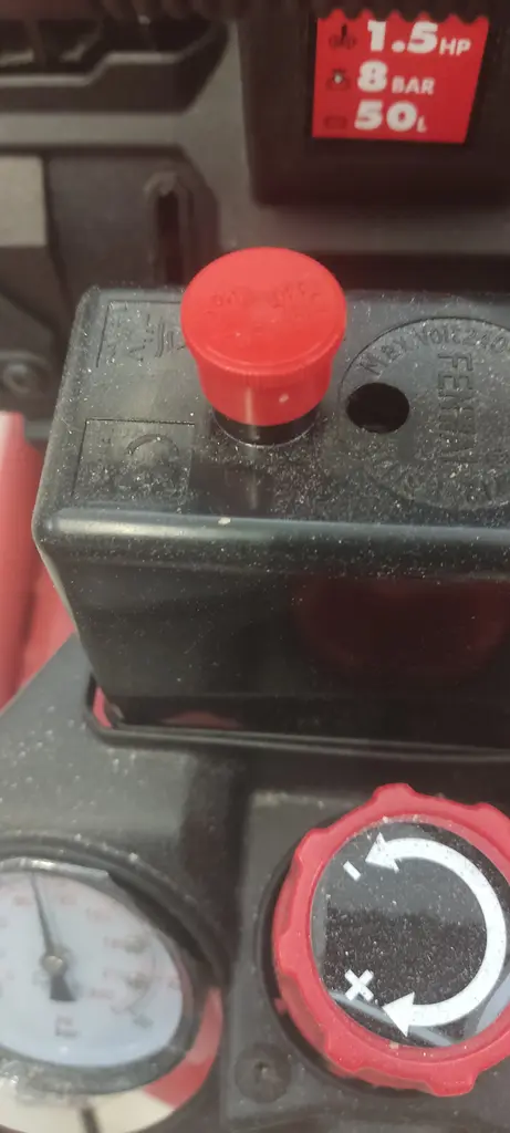
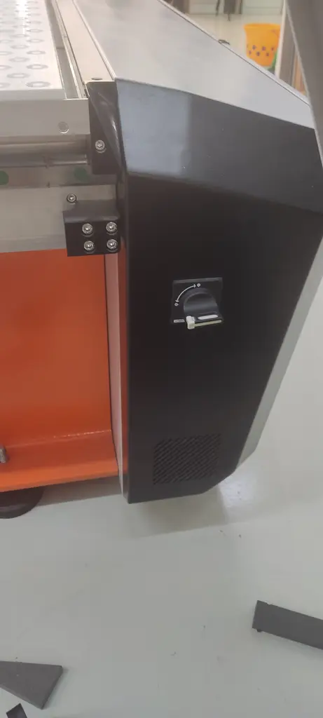
- Air Compressor & Power: Switch on the air compressor (required for the pneumatic ATC system) and power on the Ouplan 3020 and InoControl software. (Switching on the air compressor requires pulling the button up which is not intuitive)
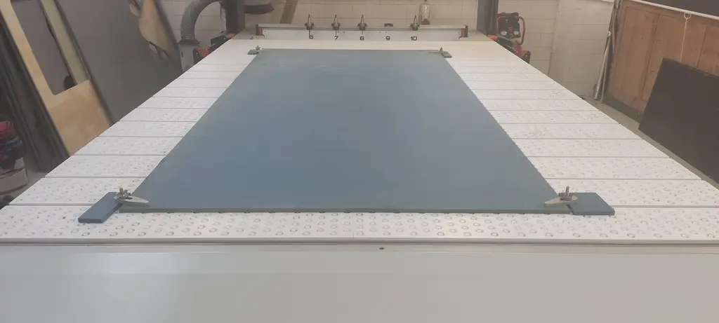
- Fixturing: Place the 12 mm sheet flat on the bed and secure it firmly around the perimeter using T-slot clamps (within the 20 mm stock margin configured in CAM).
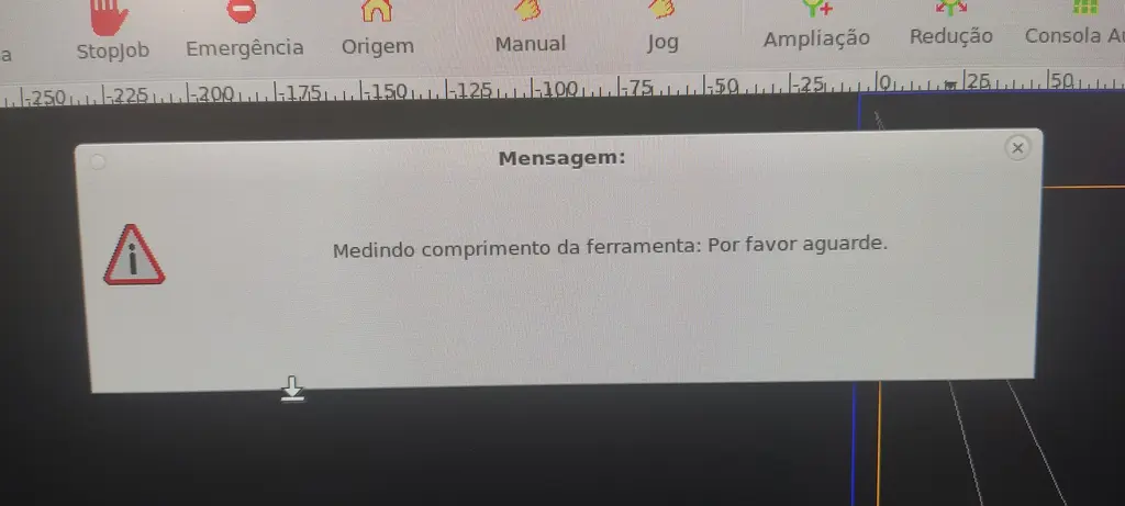
- Homing & Tool Measurement: In InoControl, home the machine (
Origin), verify that the required tools are loaded in their respective ATC slots, and run automatic tool length measurement if needed.
- Setting Work Zero (G54): Use Manual mode for coarse positioning and Jog mode (with arrow keys and step increments) to position the cutter at the front-left corner of the stock, then set the X and Y work origin.
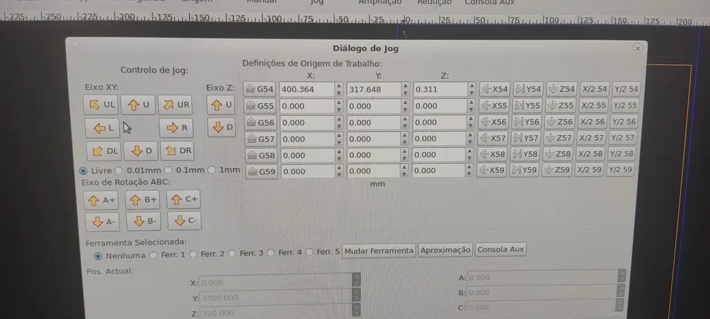
6. Running the Cut : Start the program, monitor the tool changes and cutting passes, and once complete, vacuum the dust and unclamp the sheet
Monitoring the progress:
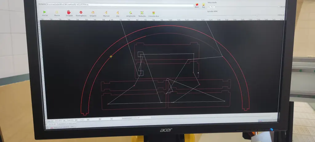
Making the bores:
The final contour:
The final result of the cut:
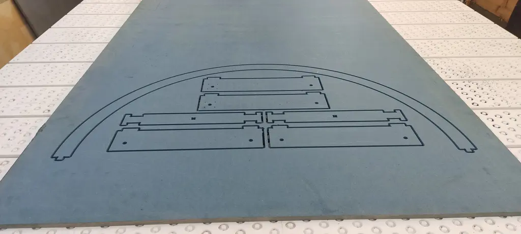
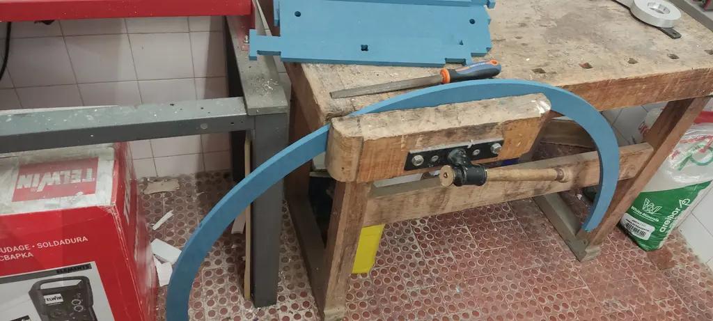
7. Post-Processing: cut the holding tabs, sand the edges, and press-fit the components together.
A visible detail of the tabs (and dog bones):
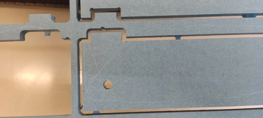
Removing the leftovers of the tabs:
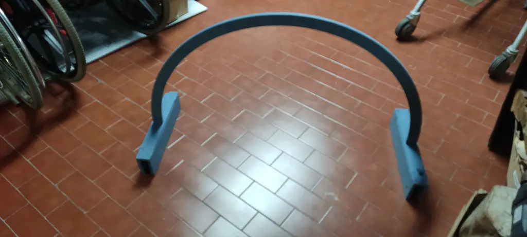
Everything pressed fit together:
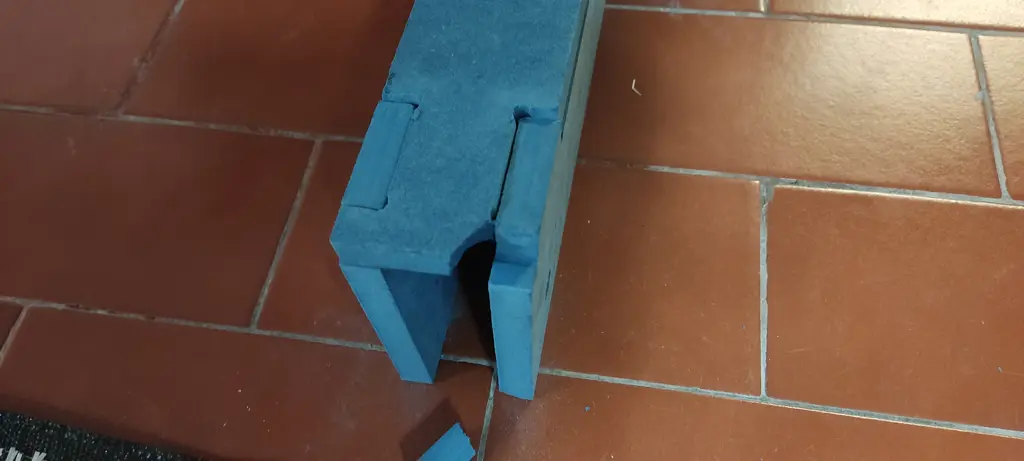
Some problems
Having the joints so close to the edge, was likely not a good idea, as one of the edges broke when press fitting:
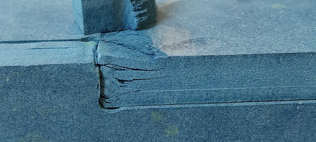
Also, generally I found that, despite measuring the kerf ( as 0.1 mm) in the group assignment, and accounting for that in the design, it was very hard to press fit, and I often had to use a rasp to remove excess for fear of breaking it. I would probably not account for kerf in a next iteration or even add more space so that it would fit better.
Here’s one place where the press fit was too tight:
Also, when fitting a shaft for the wheels (more on that later) I found that several bores didn’t fit equally with the same shaft.
I think that, unlike the kerf for the laser cutter, the kerf for the CNC is not as consistent.
7. 3D-Printed Wheels, Rim & Custom Shaft Sleeve (OpenSCAD)
To drive the structure along the support boxes, I needed custom wheels (with a rigid PLA rim and a flexible TPU tire) and a custom shaft extender sleeve to couple the NEMA 17 stepper motor shaft across the wooden box walls. Because I am more comfortable with OpenSCAD than the Python CAD frameworks, I used AntiGravity to generate the initial wheel and tire models, and then manually iterated on the OpenSCAD code to adapt the rim and create the shaft sleeve.
📄 Full Conversation & Code History: The complete prompt logs, design walkthrough, and all manual OpenSCAD iterations have been extracted to wheels_conversations.md.
Initial Main Prompt
The design of the wheel and tire started from the following prompt in AntiGravity:
“Design in openscad a wheel. Design seperately the rim and the tire. The rim is expected to be 3d printed in PLA and the tire in TPU. The rime must have a fitting for a NEMA17 shaft. The total radius of the wheel, including the tire is to be 5 cm”
AI-Generated Iterations (rim.scad, tire.scad, wheel.scad)
- Initial Multi-Material Wheel & Tire (
tire.scad,rim.scad): - TPU Tire (
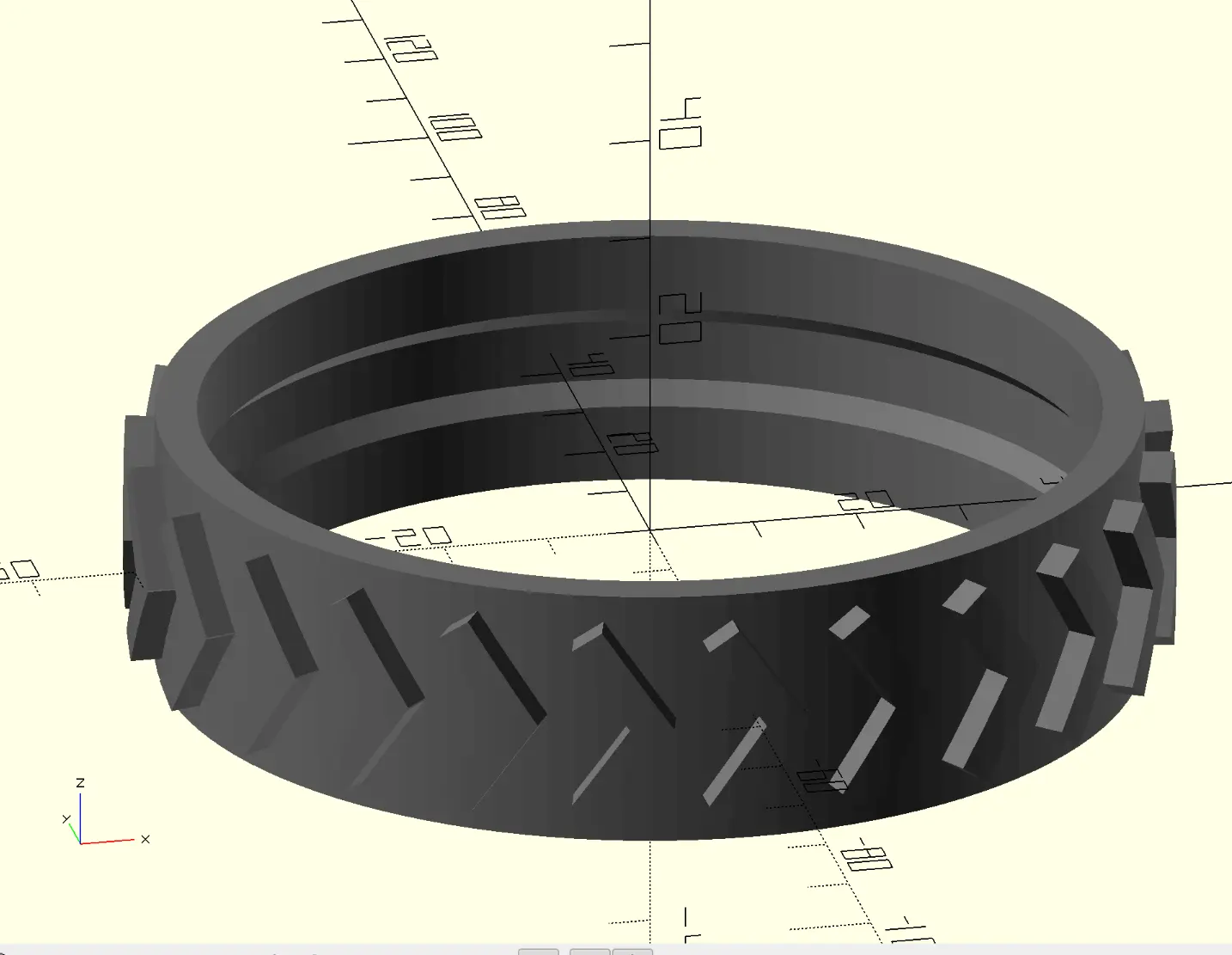
tire.scad): Designed with a50 mmtotal outer radius (100 mmdiameter),43 mminner radius, and25 mmwidth, featuring 24 aggressive V-shaped chevron treads (3 mmdeep) for traction and an internal trapezoidal groove to lock onto the rim. - PLA Rim (
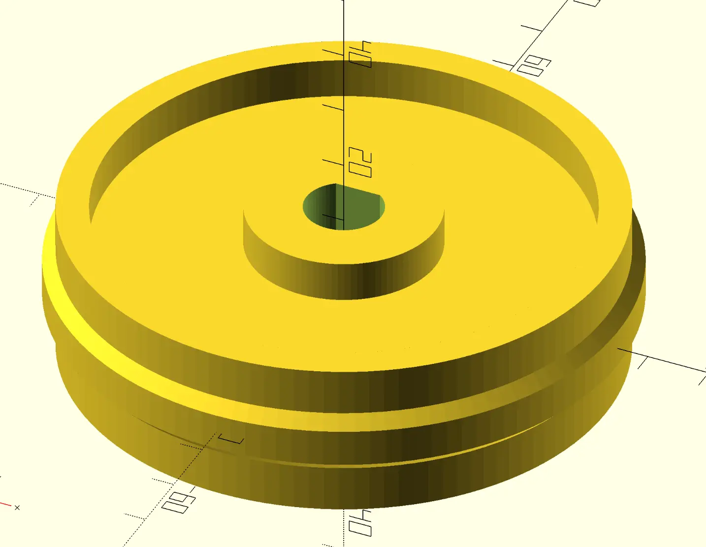
rim.scad): Designed with a43 mmouter radius, a matching2 mmtall trapezoidal locking ridge on the outer perimeter to prevent the TPU tire from slipping axially, a central hub (r = 10 mm) with a 5 mm NEMA 17 D-shaft bore, a horizontal M3 set-screw hole + captive M3 hex nut trap perpendicular to the D-flat, and 5 curved turbine spokes. - Replacing Disconnected Spokes with a Solid Disc:
- In the first generated version, the curved turbine spokes had a bug where they did not properly bridge the hub and outer rim. I prompted: “I like the tire but not the internal part of the rim. Just make it a straight solid. Besides, the internal parts where’t even touching the external parts”.
- The spokes were replaced with a solid connecting cylinder, and a
Ø7 mmradial clearance channel was bored from the outside of the rim down to the hub so a short M3 set screw and Allen key could still reach the captive nut trap. - Recessing the Inner Rim Web:
- To save filament and print time without sacrificing strength, I prompted: “looking better, but the internal part of the rim does not have to be as thick as the outside”.
- The inner disc thickness was reduced from
25 mmto12 mm(creating a6.5 mmdeep recess on both faces while keeping the outer tire-mounting ring and central hub at the full25 mmwidth) and slightly overlapped to guarantee a clean 2-manifold STL export.
Mechanical Integration & Manual OpenSCAD Modifications
When integrating the wheels into the wooden support boxes (where the inner span between walls is 30 mm and the wooden wall is 9–12 mm thick), the standard 24 mm long NEMA 17 motor shaft was too short to pass through the wooden wall, support the 25 mm wide wheel, and reach the opposite wall. Rather than ordering metal shaft extenders, I decided to 3D-print a custom Ø12 mm shaft extender sleeve with an external D-profile and modify the OpenSCAD files manually:
- Enlarging the Rim Hub & D-Bore (
rim2.scad&wheel.scad): - Modified
nema17_shaft()inrim2.scadto enlarge the D-bore from the5 mmstepper shaft to fit the new12 mmD-shaft sleeve. - Increased the central hub radius from
r = 10 mmtor = 15 mmto maintain wall thickness around the larger12 mmbore. - Removed the
grub_screw_cutout()module and access channel, since the wheel now slides directly onto the custom12 mmD-sleeve and is captured axially between the wooden box walls. - Designing the Custom Shaft Extender Sleeve (
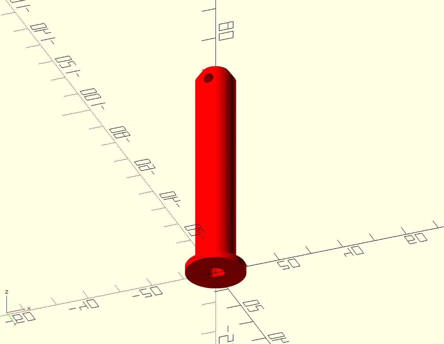
wheelshaft.scad→wheelshaft4.scad): - Designed a 3D-printed shaft sleeve from scratch with a bottom retaining flange (to keep it trapped inside the motor recess), an external D-profile along its length (to positively drive the wheel rim), and a tapered tip with a transverse cross-hole at the far end (to guide it through the opposite wooden wall and lock it with a retaining pin).
- Iterated through four versions (
wheelshaft.scadtowheelshaft4.scad) primarily to add the internal female D-socket at the base for the NEMA 17 motor shaft (which was forgotten in the first draft) and to fine-tune the 3D-printing tolerances—both on the internal motor socket so the metal shaft would press in cleanly, and on the outer diameter so the sleeve could rotate inside the CNC-bored wooden holes.
The rim:
The tire:
The D shaft sleeve:
8. Hero shot
Here’s the final result with fitted wheels and shaft sleeves for the NEMA motors: