Individual assignment
First version
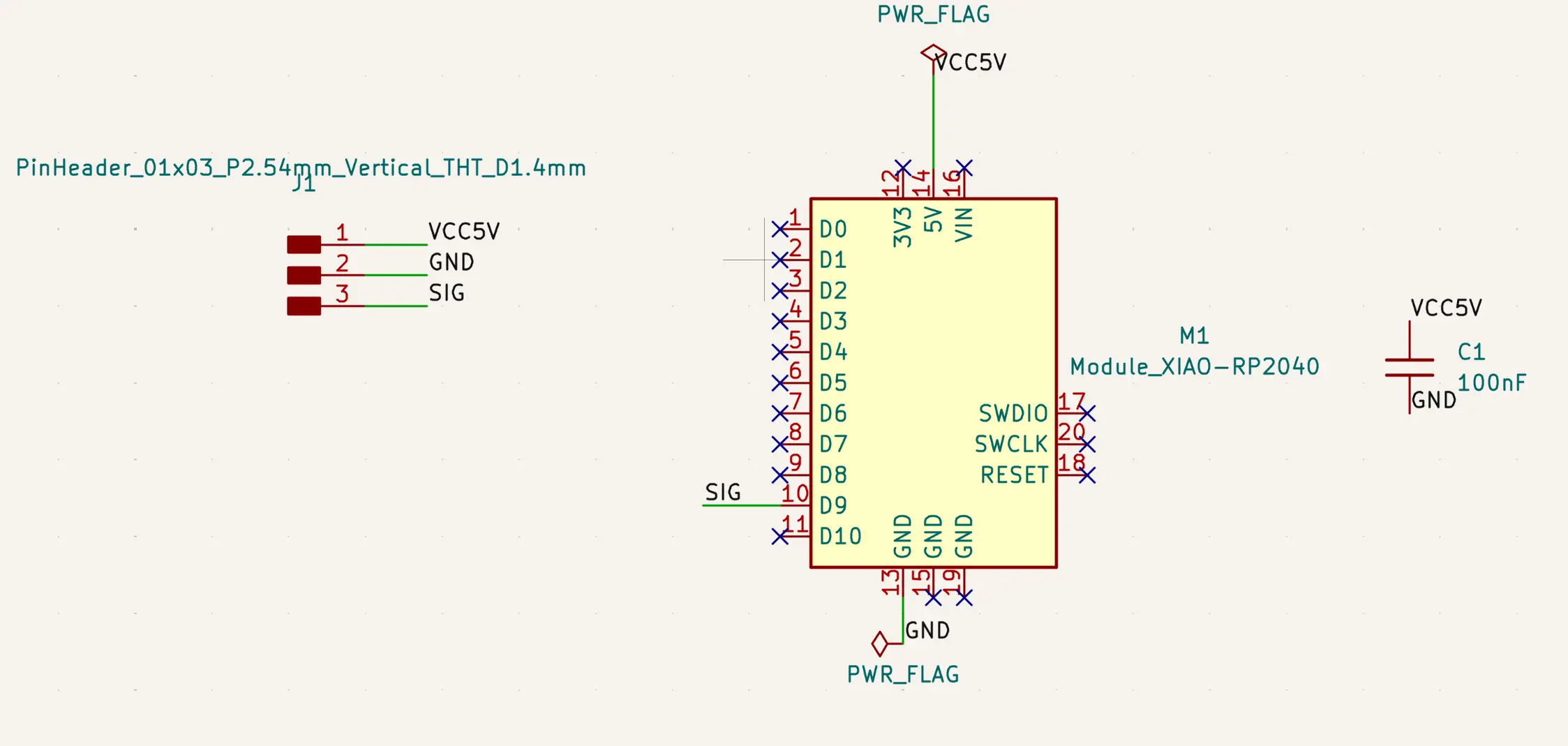
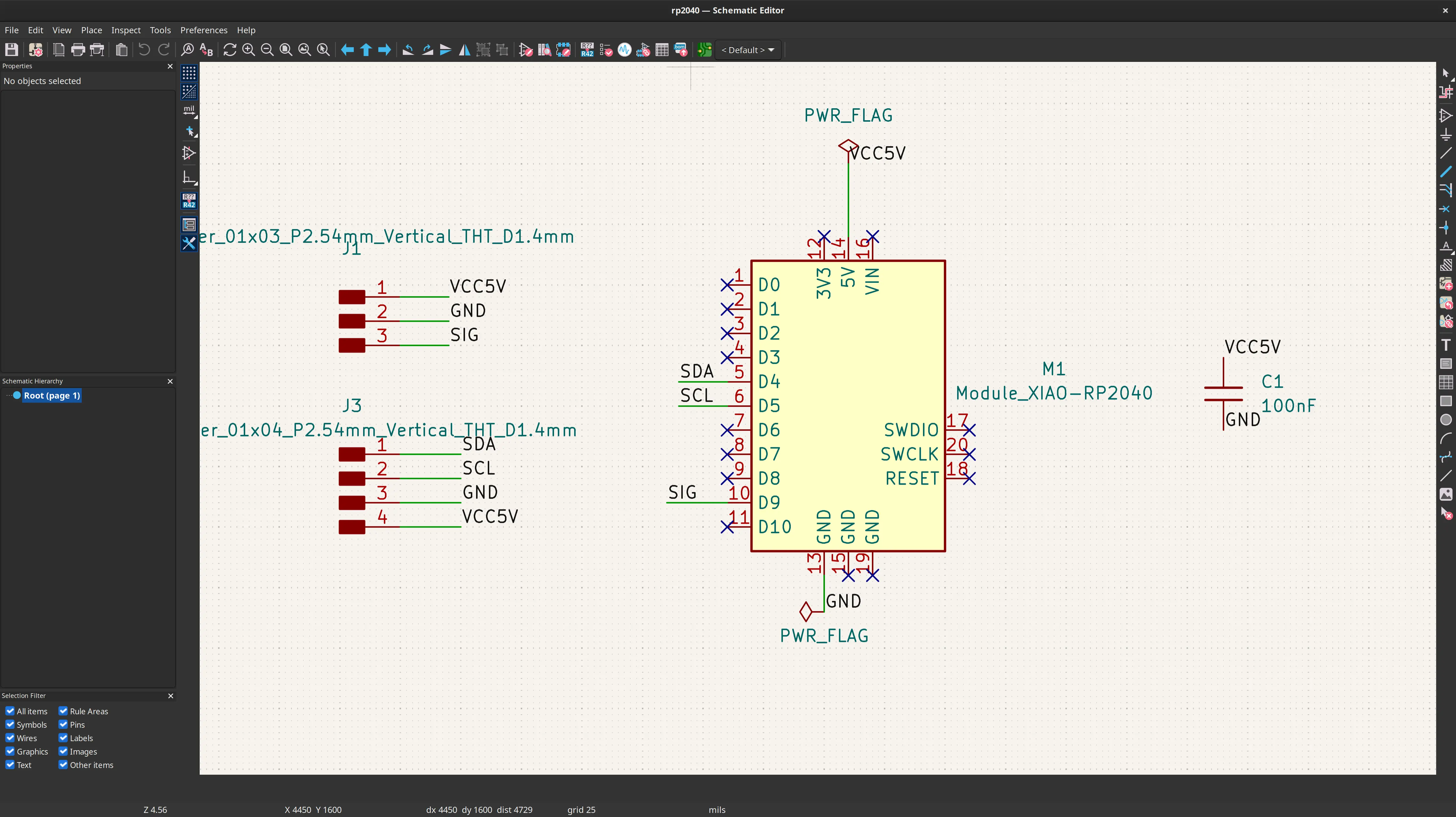
For the individual assignment I decided to make a small board with a Xiao RP2040 and control the small servo motor we used in the group assignment.
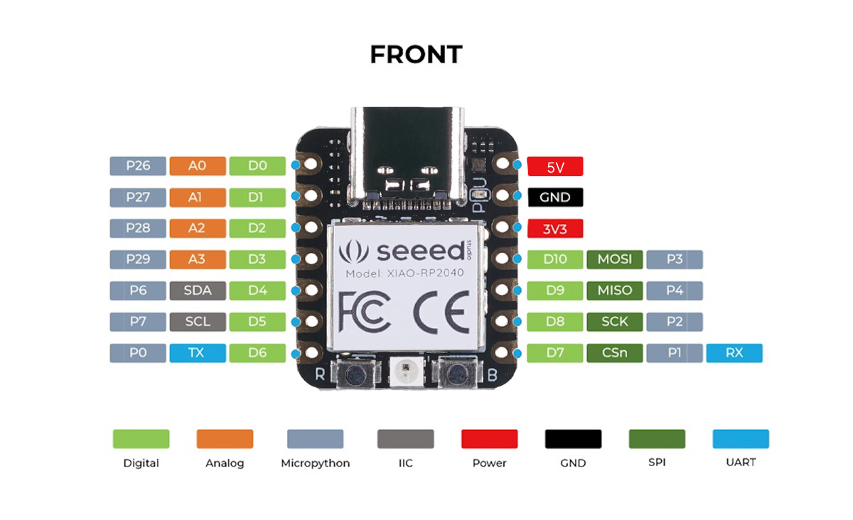
Given that the servo motor is not going to be soldered to the board, the schematic is quite simple:
Given that the process of describing the design of the PCB has already been extensively described in week 6, I’ll just document the main steps here.
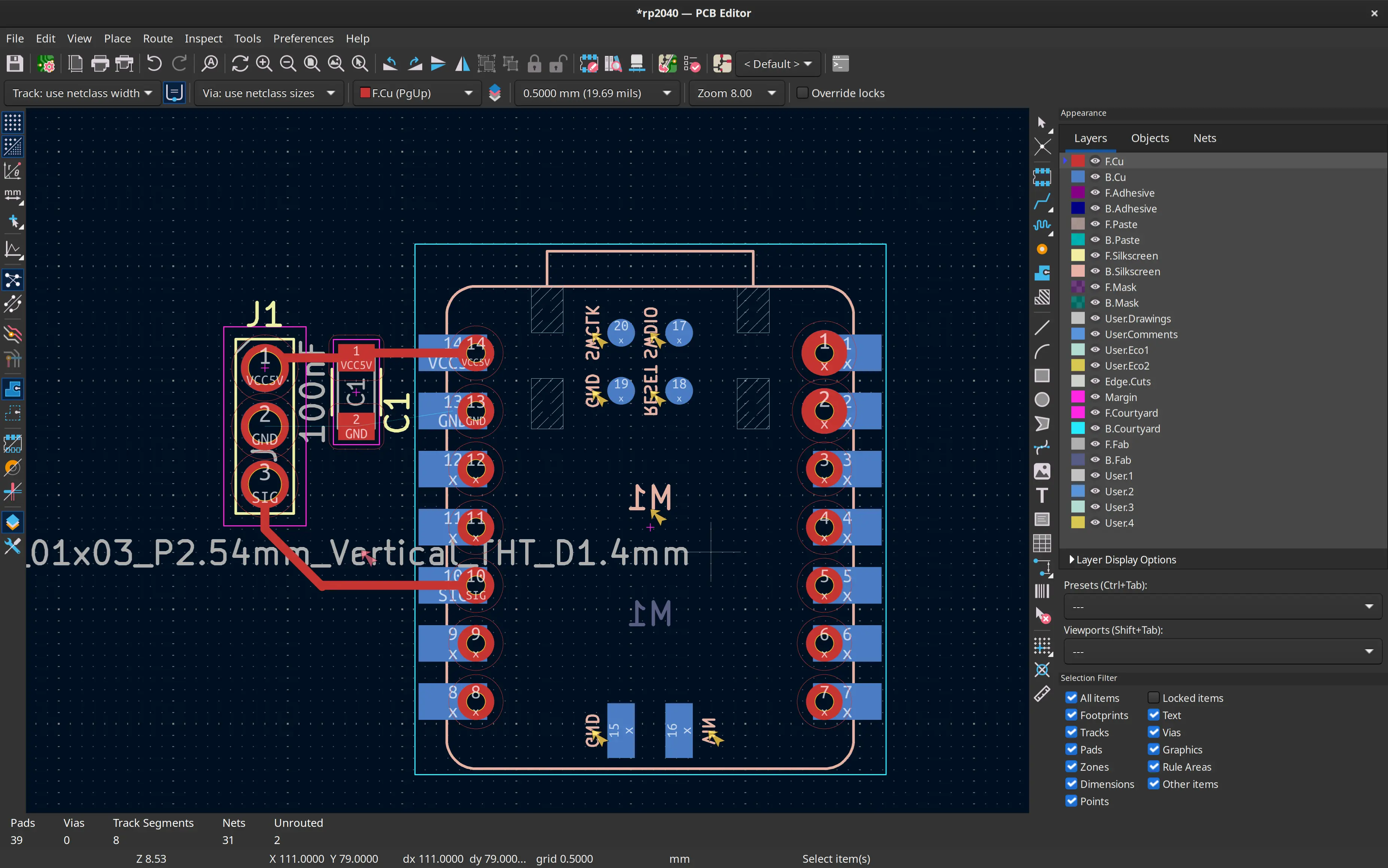
My lab instructor André Rocha, requested we should not solder the microcontroller to the board, so we could just move it between boards on each week. However soldering the female or other through-hole pins to the board in the usual orientation poses a problem with soldering because of the plastic on the pins, and because we’re using single side boards.
Although there are some pins that can be soldered they are not as robust as the through hole ones. So, instructor Ricardo Marques suggested I flipped the board and placed it below the board, which I thought is a nice workaround.
This is how it looks with the microcontroller flipped:
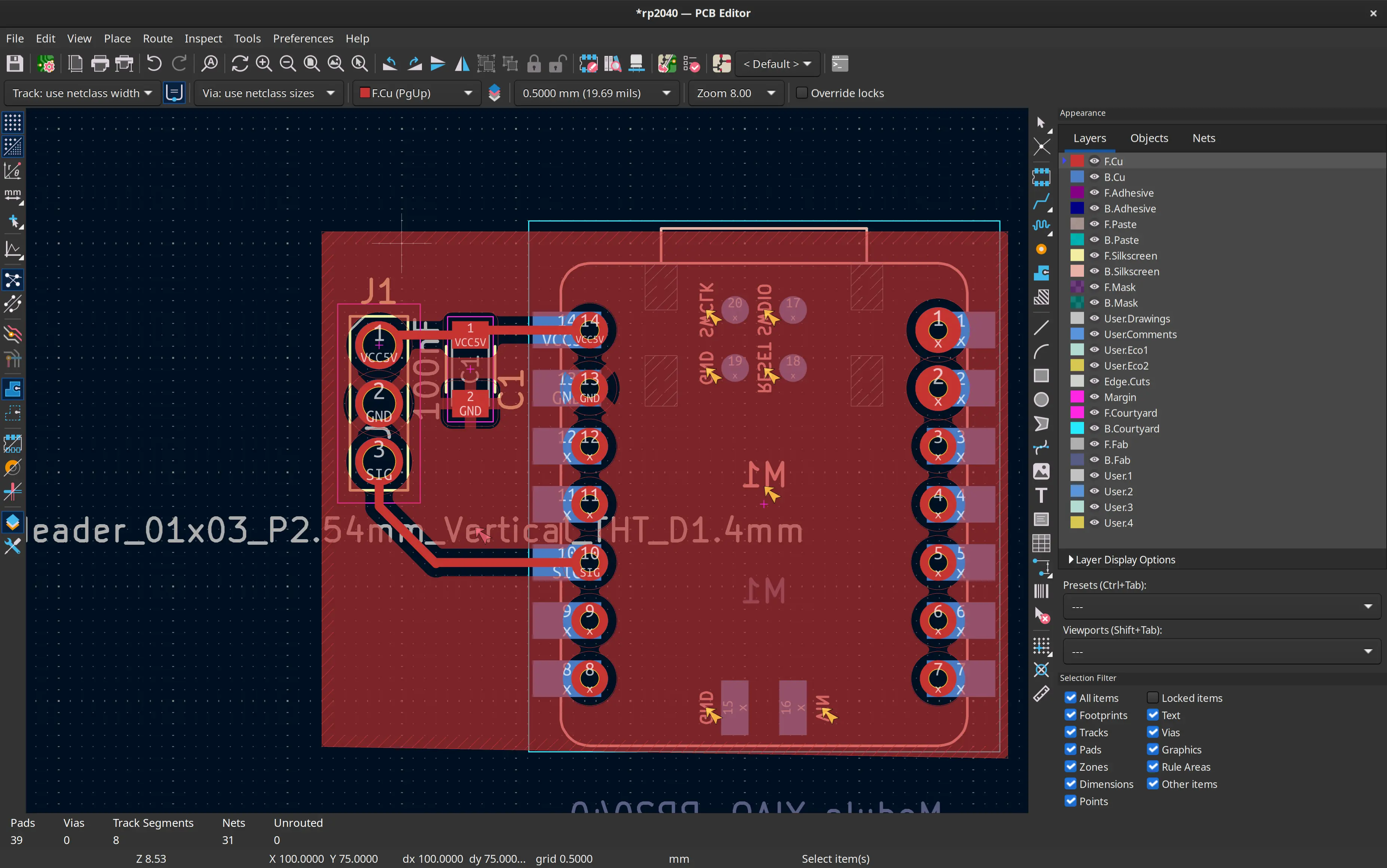
I then add the ground layer:
And define the edges of the board:
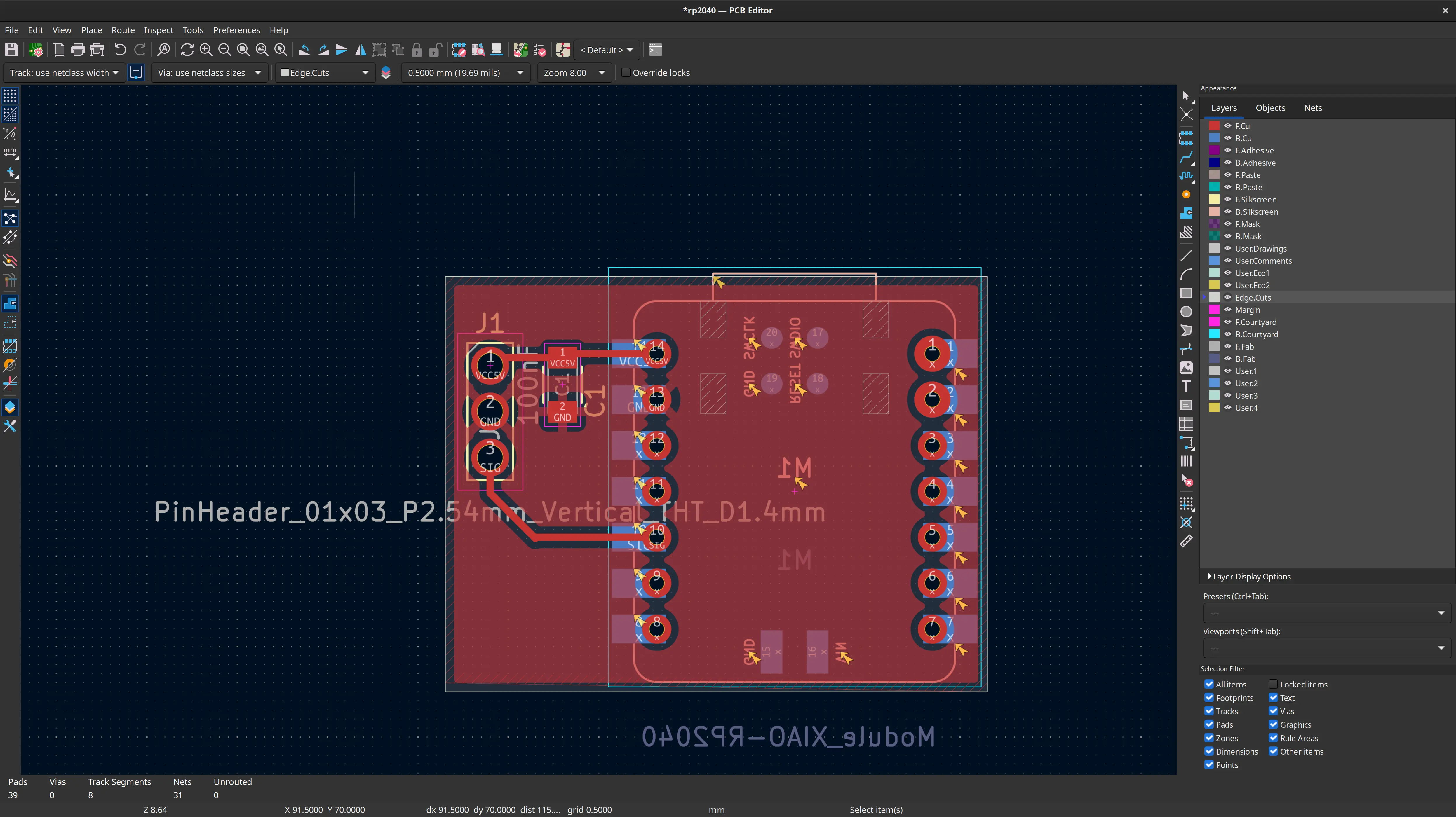
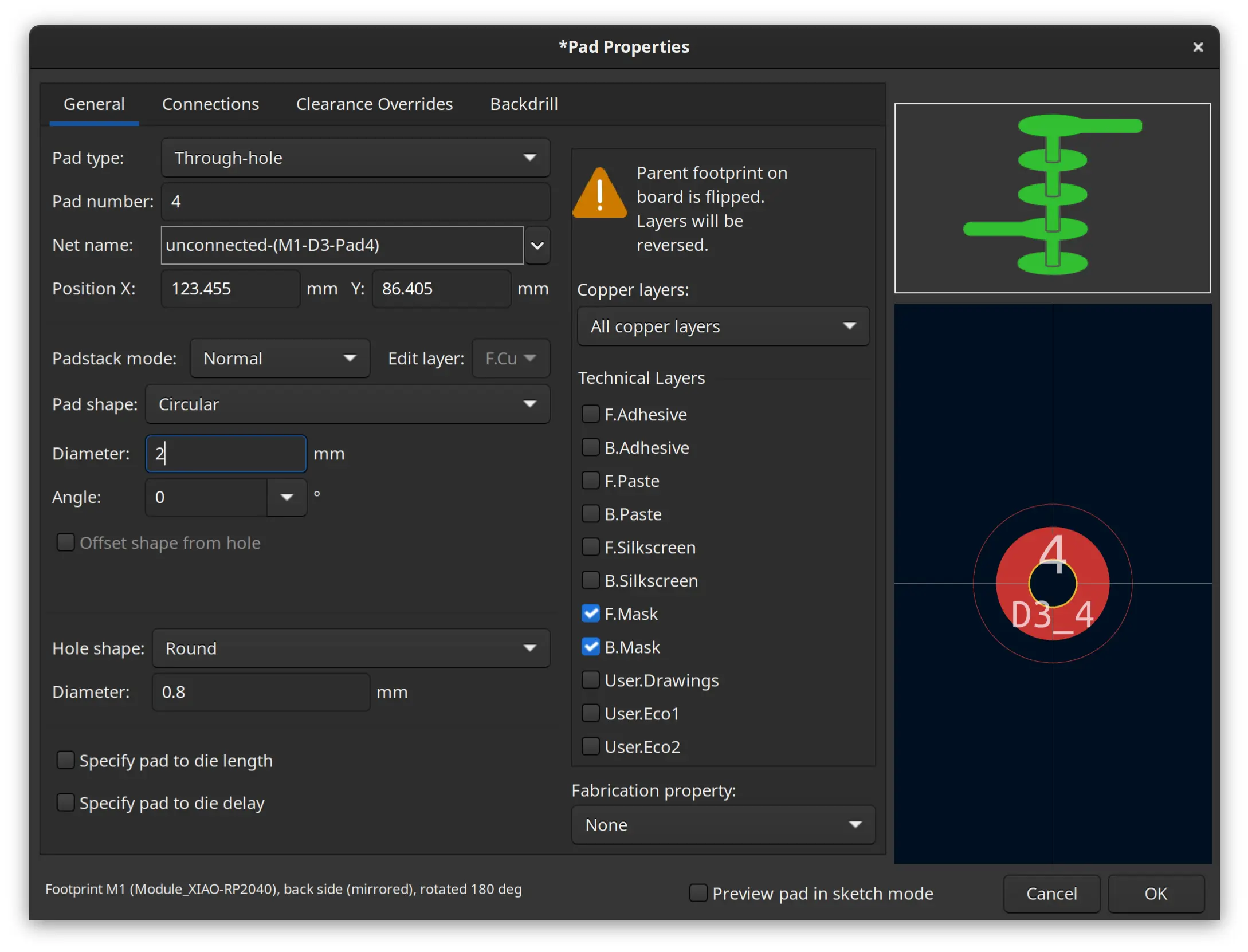
Because the smallest available drill is larger than the ideal holes, I manually increased the pads diameter to 2mm:
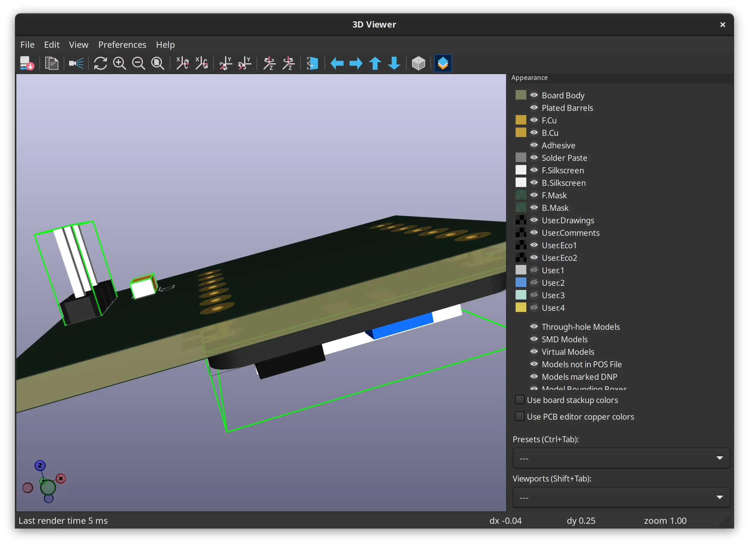
This is the 3D render of the board, minus the female pins.
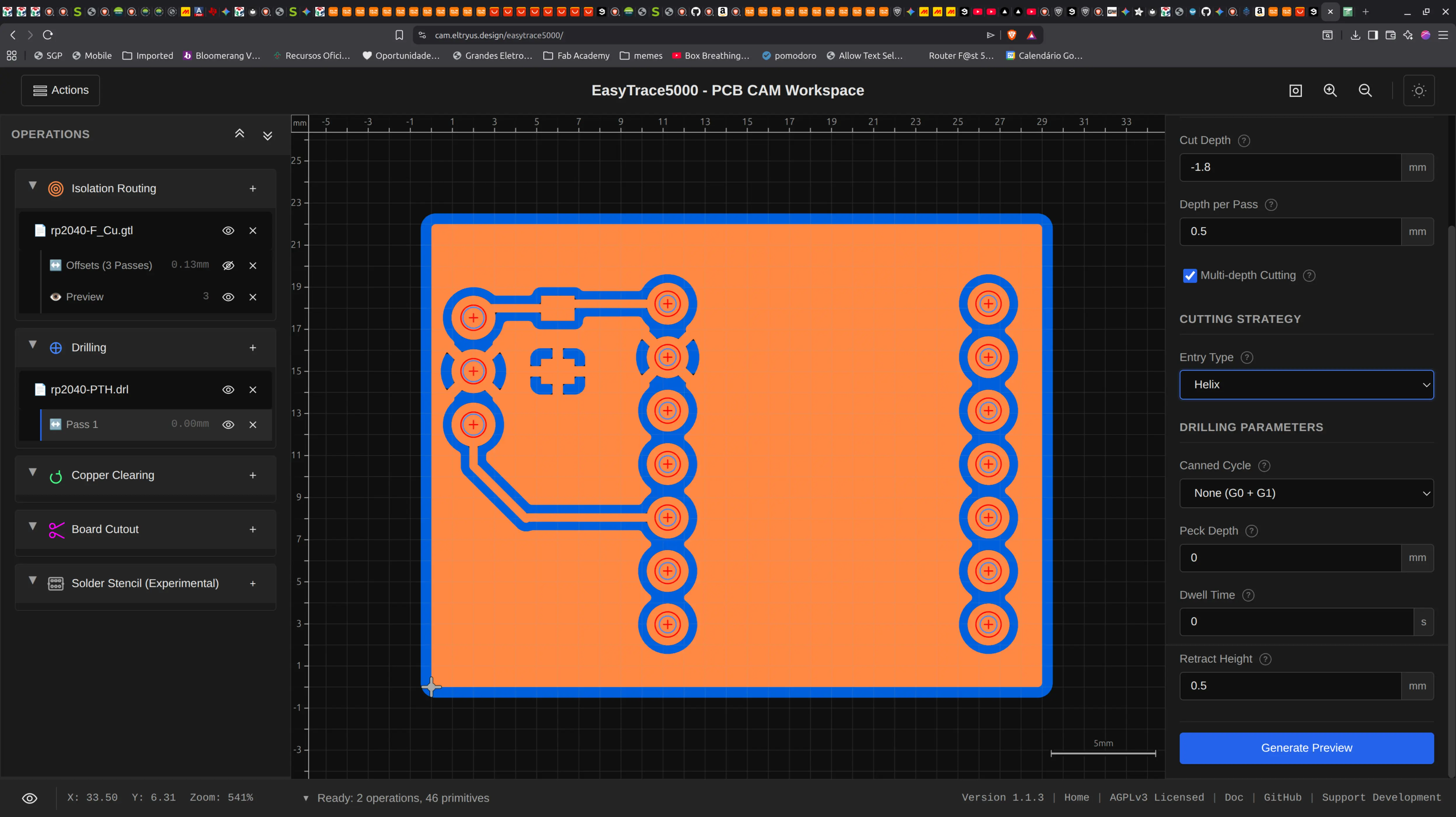
I imported the Kicad files to EasyTrace5000:
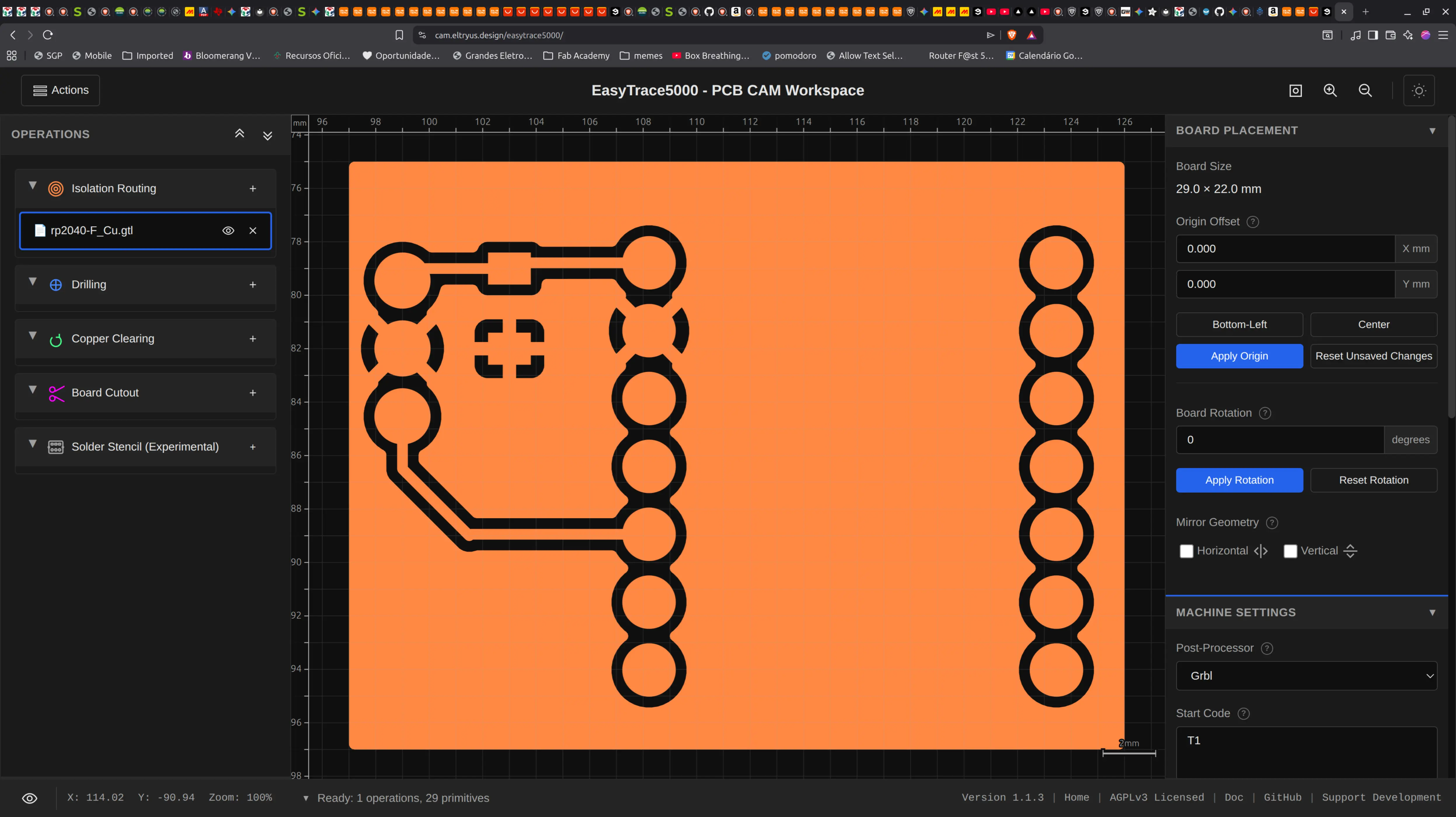
It gives me some warnings about the tool being bigger than the designed hole size, but I’ll ignore that for now, since I already increase the pad size to account for that.
After going through the process of importing the output of EasyTrace5000 into candle, here’s the resulting board:
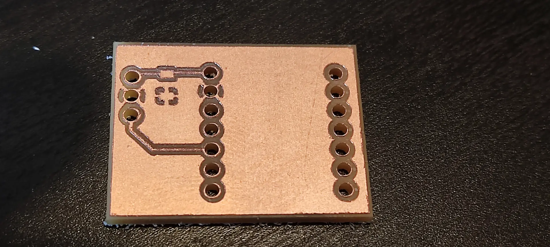
This is how far in the week I got.
Review and 2nd version
This time I got to present my week and Neil had some comments regarding having more clearance between tracks and GND:
(comments on the board itself are around the 16 mn mark)
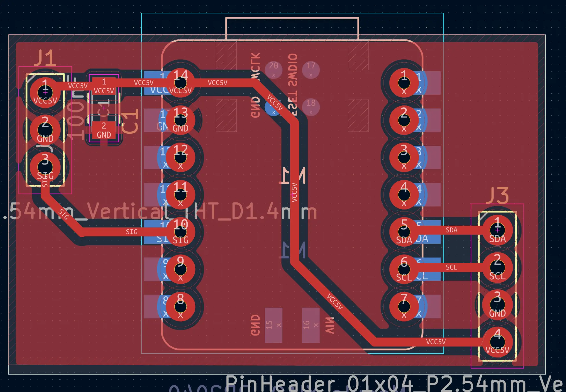
Also, since this day we got introduced to the networking assignment, I redesigned the board to take into account Neil’s comments and also include pins to be able to communicate with I2C:
On the advice of Ricardo, I also included 2 wires to share GND and VCC, so I could power another Xiao with VCC rather than USB and share GND between boards.
This is how the PCB looks like:
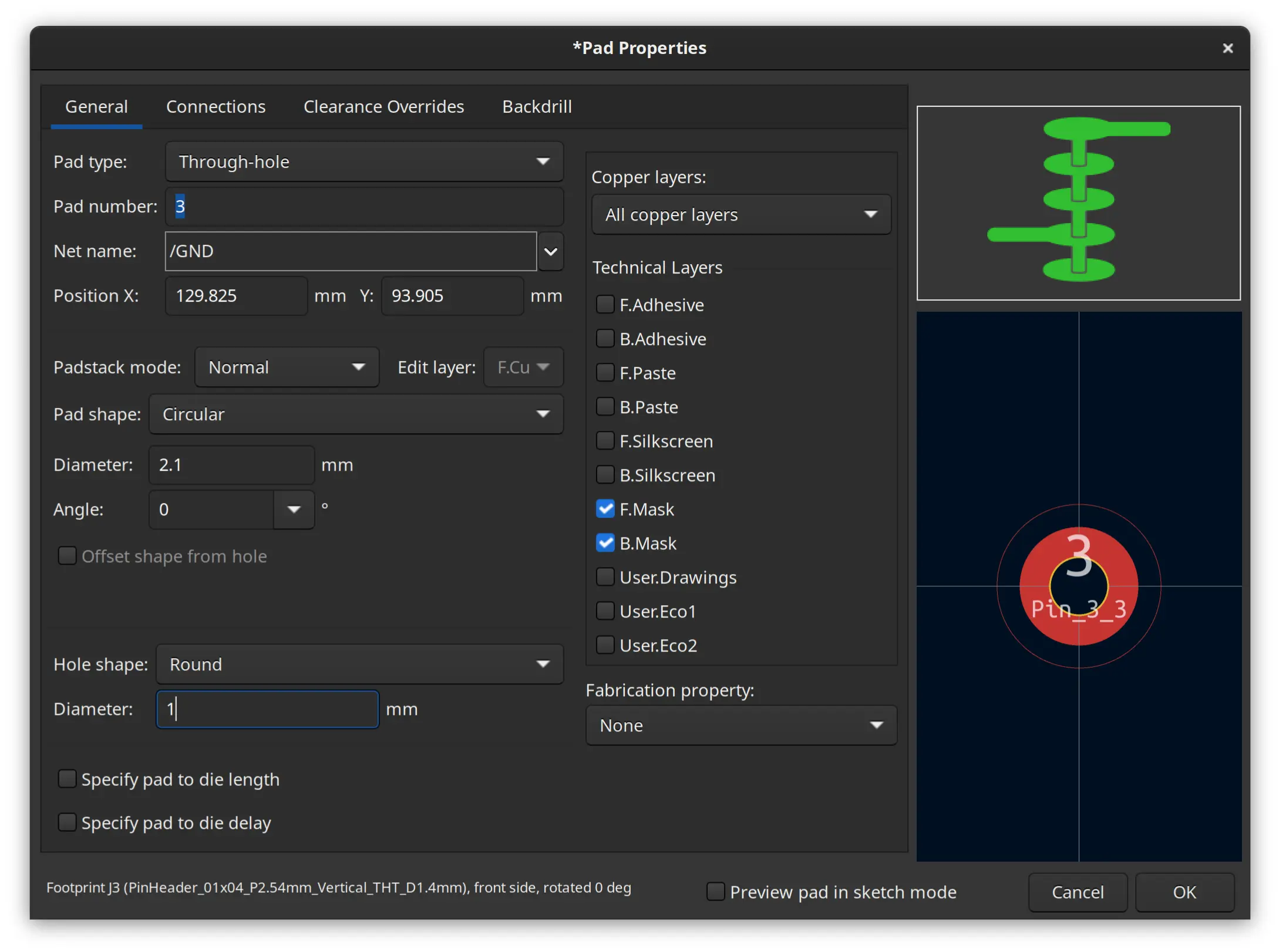
I manually edited the holes of the pin header to reduce hole diameter to 1 mm, because it is enough, and it’s better to have some more copper for the solder to connect, and I now had access to 1 mm wide drill (previously it was 1.5 mm):
I then exported Kicad’s files into EasyTrac5000 as described in other week’s and this is the resulting board I got:
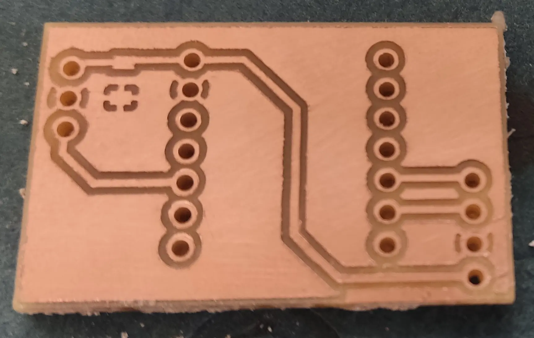
It looks a lot more robust !
I then soldered male and female pins:
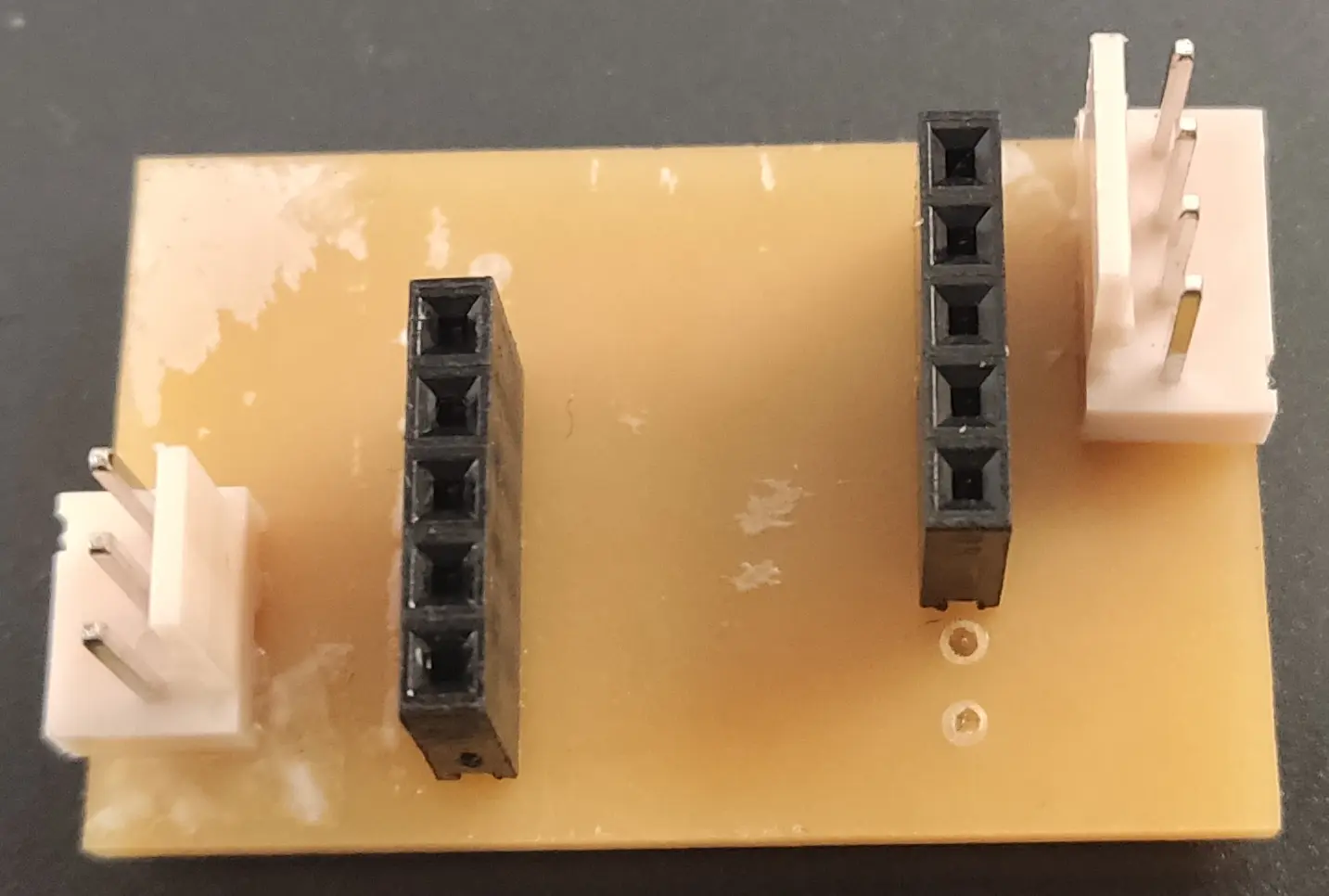
Notice that unfortunately we didn’t have any female pins of size 7, and I had to make do with the size 5 we had 😅
Luckily I didn’t need all the pins for this board ! 😁
On the solder side, it looks like this:
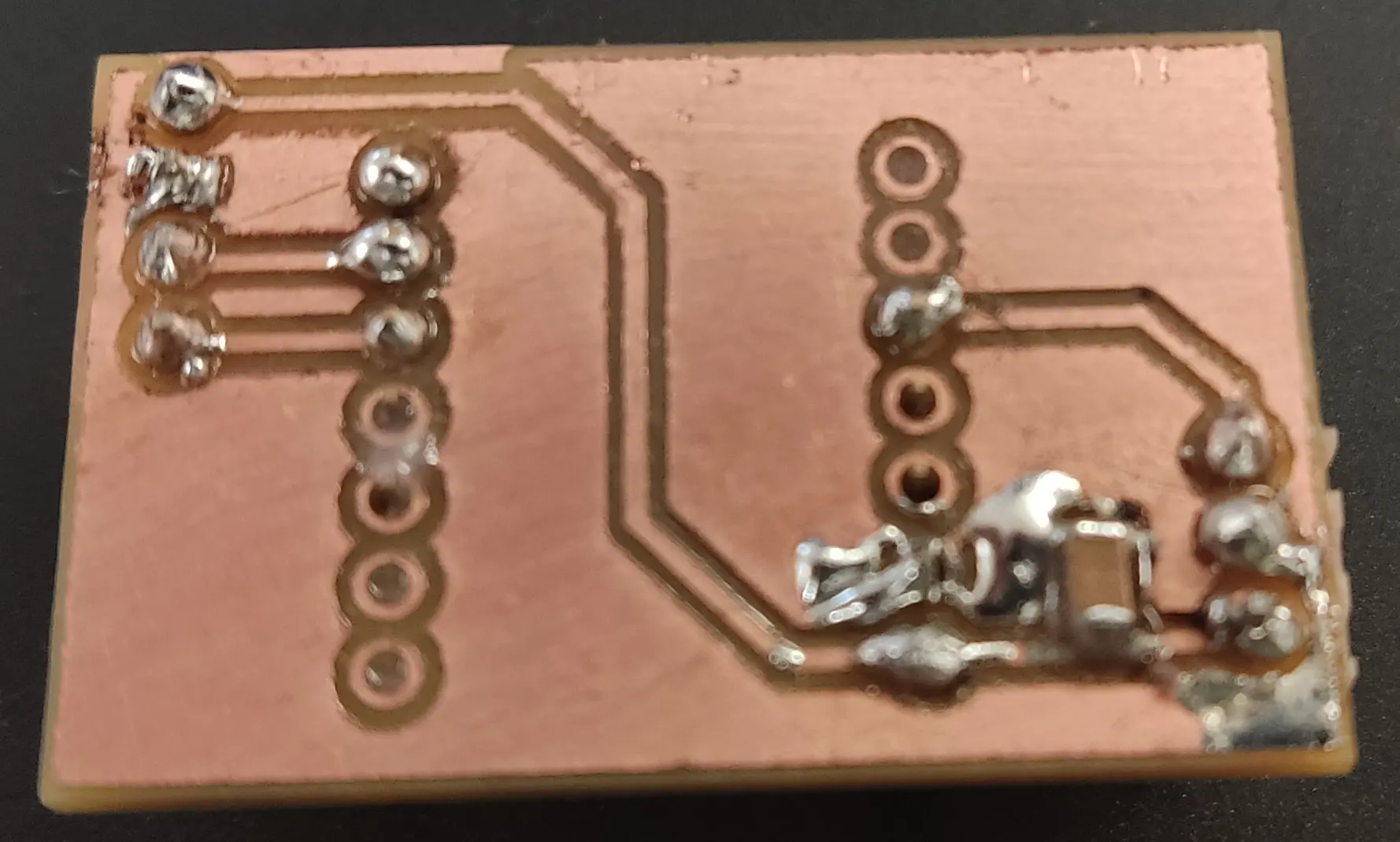
For the capacitor, I initially designed it as a 100 nF decoupling, but after Neil’s explanation on the difference between bulk and decoupling capacitors, and since Ricardo mentioned the Xiao already has decoupling when powered through USB, we picked the highest SMD one we had available which was 10 µF.
I tested everything with the multimeter to make sure all tracks were connecting where they should and there were no shorts.
Finally I plugged the the Xiao and connected to USB and programmed it with the default Servo sketch slightly modified:
/* Sweep
 by BARRAGAN <http://barraganstudio.com>
 This example code is in the public domain.

 modified 8 Nov 2013
 by Scott Fitzgerald
 https://www.arduino.cc/en/Tutorial/LibraryExamples/Sweep
*/

#include <Servo.h>

Servo myservo;  // create Servo object to control a servo
// twelve Servo objects can be created on most boards

int pos = 0;    // variable to store the servo position

void setup() {
  myservo.attach(D9,500,2500);  // attaches the servo on pin D9 to the Servo object and defines the min and max pulse width in microseconds
}

void loop() {
  for (pos = 0; pos <= 180; pos += 1) { // goes from 0 degrees to 180 degrees
    // in steps of 1 degree
    myservo.write(pos);              // tell servo to go to position in variable 'pos'
    delay(15);                       // waits 15 ms for the servo to reach the position
  }
  for (pos = 180; pos >= 0; pos -= 1) { // goes from 180 degrees to 0 degrees
    myservo.write(pos);              // tell servo to go to position in variable 'pos'
    delay(15);                       // waits 15 ms for the servo to reach the position
  }
}
The servo needs a range of pulse widths to set the desired angle. The library conveniently wraps the calls to the the correct angles, as long as one initializes them properly.
The original initialization code was just myservo.attach(9) and I changed it to myservo.attach(D9,500,2500) to get the full range, otherwise I would only get about 90 degrees with the defaults. Also notice the correct pin, which is D9 and not 9 like in Arduino.
Despite the specs saying that the range of the angle would be between 1000 and 2000 µs, in practice setting it to 500 to 2500 µs got me the full range. I got these values through experimentation.
The remainder of the loop code just cycles through the full range of motion back and forth, effectively doing a sweep.
Finally we can see the result with the full range of motion:
Annoyingly it was only when connecting the wires to the board that I noticed that in the servo the order of the wires is GND, VCC, SIG whereas I designed VCC, GND, SIG 🤦
So, instead of connecting it directly to the board I needed a few more DuPont wires, just to invert the 2 wires 🤷♂
Also before I got this working, I wasted a lot of time trying to figure out why this wasn’t working. I checked with the mutimeter again, before finally realizing the DuPont wire I was using for signal was faulty 🤦
All in all, I’m happy that my amazing soldering skills didn’t waste another board 💪😁