Individual assigment
Intro
Since I already used the serial protocol in the group assignment, I wanted to try something else and picked I2C because it is a popular protocol.
The plan was to use the board used for input week to be the master, and use for slaves the board used for output week, plus a commercial dev board like the pico W.
But things are never quite that simple, are they ? 🤷♂
First try
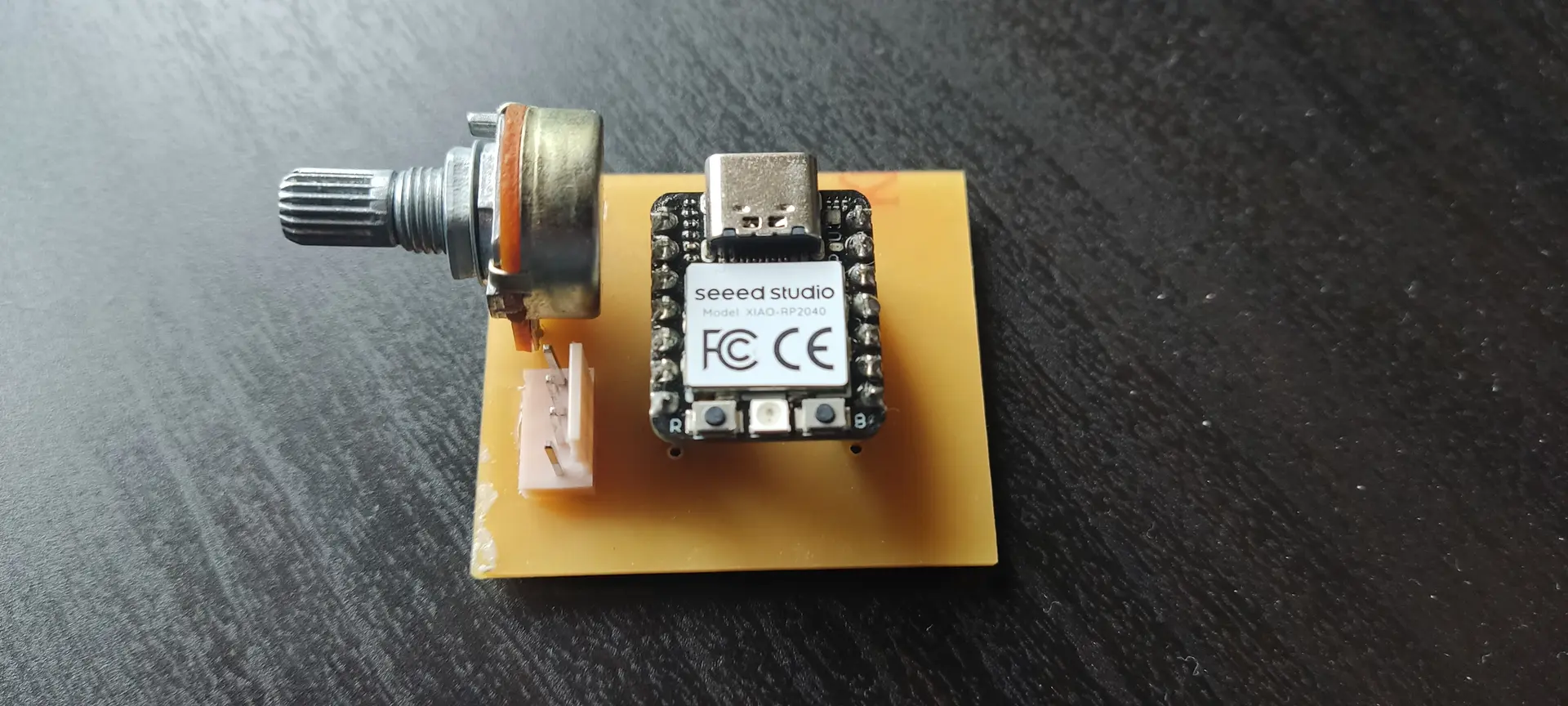
Since the board for input week didn’t yet have the pull up resistors, or connectors for the I2C, I soldered them, and here what it looks like:
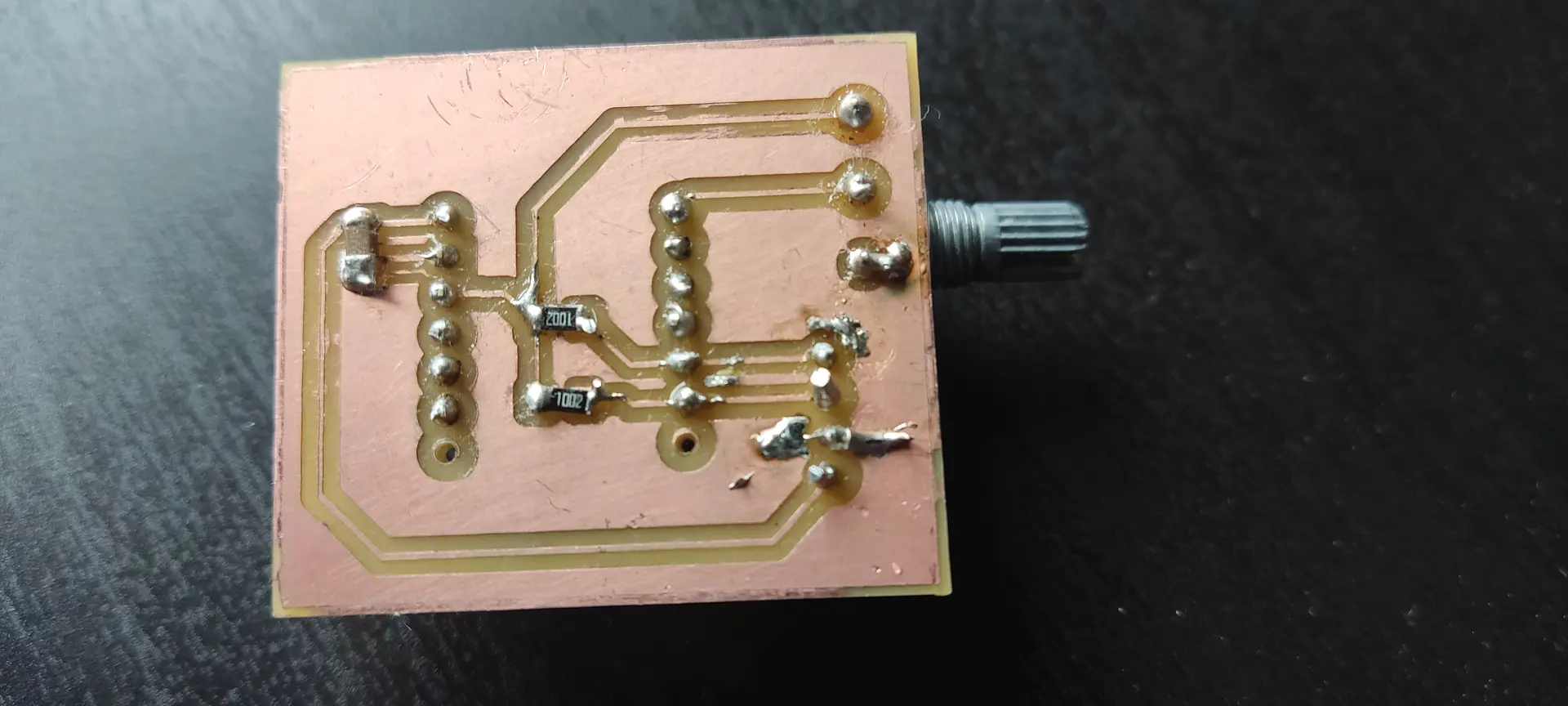
And the bottom:
I modified the source from the input week to include code to to send a different byte to 2 different slaves, according to the value read the the analog pin A0, corresponding to potentiometer position.
Master:
#include <Adafruit_NeoPixel.h>
#include "Wire.h"

#define I2C_SLAVE1_ADDR 0x55 // stepper
#define I2C_SLAVE2_ADDR 0x56 // pico

uint32_t i = 0;

#define SAMPLES 50
#define PIN_NEOPIXEL_POWER 11   // Onboard NeoPixel power Pin
#define NUMPIXELS    1    // Just the one LED

// Initialize the NeoPixel object
Adafruit_NeoPixel pixels(NUMPIXELS, PIN_NEOPIXEL, NEO_GRB + NEO_KHZ800);

void setup() {

  // Requirement for some XIAO RP2040  neopixel versions: Power the internal rails
  pinMode(PIN_NEOPIXEL_POWER, OUTPUT);
  digitalWrite(PIN_NEOPIXEL_POWER, HIGH);
  pinMode(PIN_NEOPIXEL,OUTPUT);
  digitalWrite(PIN_NEOPIXEL, HIGH);

  pixels.begin();           // Start the NeoPixel
  pixels.setBrightness(30); // 0-255 range (30 is plenty for a desk)
  pixels.show();            // Initialize all pixels to 'off'

  Wire.begin();
}

void send(uint8_t addr, uint8_t value){
  Wire.beginTransmission(addr);
  Wire.write(value); // Sends exactly 1 byte
  Wire.endTransmission();
}

void loop() {
  float averageValue = 0;

  // Smoothing loop
  for (int i = 0; i < SAMPLES; i++) {
    averageValue += (float) analogRead(A0) / SAMPLES;
    delay(1);
  }
  Serial.println((int) averageValue);
  uint8_t txByte = constrain(averageValue / 4, 0, 255); //input was 0-1023, so we just need to downscale to 0-255

  // Threshold logic
  if (averageValue <= 340) {
    // Set color to RED (Red=255, Green=0, Blue=0)
    pixels.setPixelColor(0, pixels.Color(255, 0, 0));
      //Write message to the slave
    send(I2C_SLAVE1_ADDR, 0);
    send(I2C_SLAVE2_ADDR, 0);

  }
  else if (averageValue >= 680){
    // Set color to GREEN (Red=0, Green=255, Blue=0)
    pixels.setPixelColor(0, pixels.Color(0, 255, 0));
    send(I2C_SLAVE1_ADDR, 180);
    send(I2C_SLAVE2_ADDR, 2);
  } else {
    // Set color to Yellow. Making green 255 would make it closer to white
    pixels.setPixelColor(0, pixels.Color(255, 130, 0));
    send(I2C_SLAVE1_ADDR, 90);
    send(I2C_SLAVE2_ADDR, 1);
  }

  pixels.show(); // Push the color to the hardware
  delay(30);
}
Likewise I programmed the board controlling the motor from output week (ESP32C6 based), to move the motor to a different angle:
#include "Wire.h"

#define I2C_SLAVE1_ADDR 0x55

// For ESP32 Core v3.0.0+
const int servoPin = D9;
const int freq = 50;
const int resolution = 16; // 16-bit resolution (0-65535)

void onReceive(int len) {
  while (Wire.available()) {
    uint8_t value = Wire.read();
    // 50Hz = 20ms period.
    // 16-bit = 65535 steps.
    // 1ms pulse (0 degrees) = (1ms / 20ms) * 65535 = ~3277
    // 2ms pulse (180 degrees) = (2ms / 20ms) * 65535 = ~6553
    int angle = map(constrain(value, 0, 180), 0, 180, 1638, 8192);
    ledcWrite(servoPin, angle); // 0 degrees
    delay(1000);
  }
}


void setup() {
  Serial.begin(9600);
  // New syntax for ESP32 Core 3.x
  ledcAttach(servoPin, freq, resolution);

  Wire.onReceive(onReceive);
  Wire.begin((uint8_t)I2C_SLAVE1_ADDR, D4, D5);
}

void loop() {
}
I then paired the SDA, SCL and GND connectors on both boards and hoped for the best 🤞
Alas, nothing happened 🤔
Problem 1
Ok, since I was not sure why this was happening, I first retested the input board with the original code from input week, to make sure I didn’t ruin anything by adding the connector and pull up resistors. Everything was fine. Also did the usual of using the multimeter to check for continuity and isolation where these were expected. Everything seemed fine.
Not being sure if the problem was in my code, I loaded the input board with the example WireScan and the output board with the WireSlave sketches.
WireScan:
#include <Arduino.h>
#include "Wire.h"

void setup() {
  Serial.begin(115200);
  Wire.begin();
}

void loop() {
  byte error, address;
  int nDevices = 0;

  delay(5000);

  Serial.println("Scanning for I2C devices ...");
  for (address = 0x01; address < 0x7f; address++) {
    Wire.beginTransmission(address);
    error = Wire.endTransmission();
    if (error == 0) {
      Serial.printf("I2C device found at address 0x%02X\n", address);
      nDevices++;
    } else if (error != 2) {
      Serial.printf("Error %u at address 0x%02X\n", error, address);
    }
  }
  if (nDevices == 0) {
    Serial.println("No I2C devices found");
  }
}
WireSlave:
#include <Arduino.h>
#include "Wire.h"

#define I2C_DEV_ADDR 0x55

uint32_t i = 0;

void onRequest() {
  Wire.print(i++);
  Wire.print(" Packets.");
  Serial.println("onRequest");
}

void onReceive(int len) {
  Serial.printf("onReceive[%d]: ", len);
  while (Wire.available()) {
    Serial.write(Wire.read());
  }
  Serial.println();
}

void setup() {
  Serial.begin(115200);
  Serial.setDebugOutput(true);
  Wire.onReceive(onReceive);
  Wire.onRequest(onRequest);
  Wire.begin((uint8_t)I2C_DEV_ADDR);

#if CONFIG_IDF_TARGET_ESP32
  char message[64];
  snprintf(message, 64, "%" PRIu32 " Packets.", i++);
  Wire.slaveWrite((uint8_t *)message, strlen(message));
#endif
}

void loop() {}
But still, nothing would happen and the master kept saying it didn’t find any device.
Since I already did the checks on hardware and software, I thought it would be a good time to use a logic analyzer.
Problem 2
I set out to use PulseView, which is available for Linux and is open source, and a white label logic analyzer.
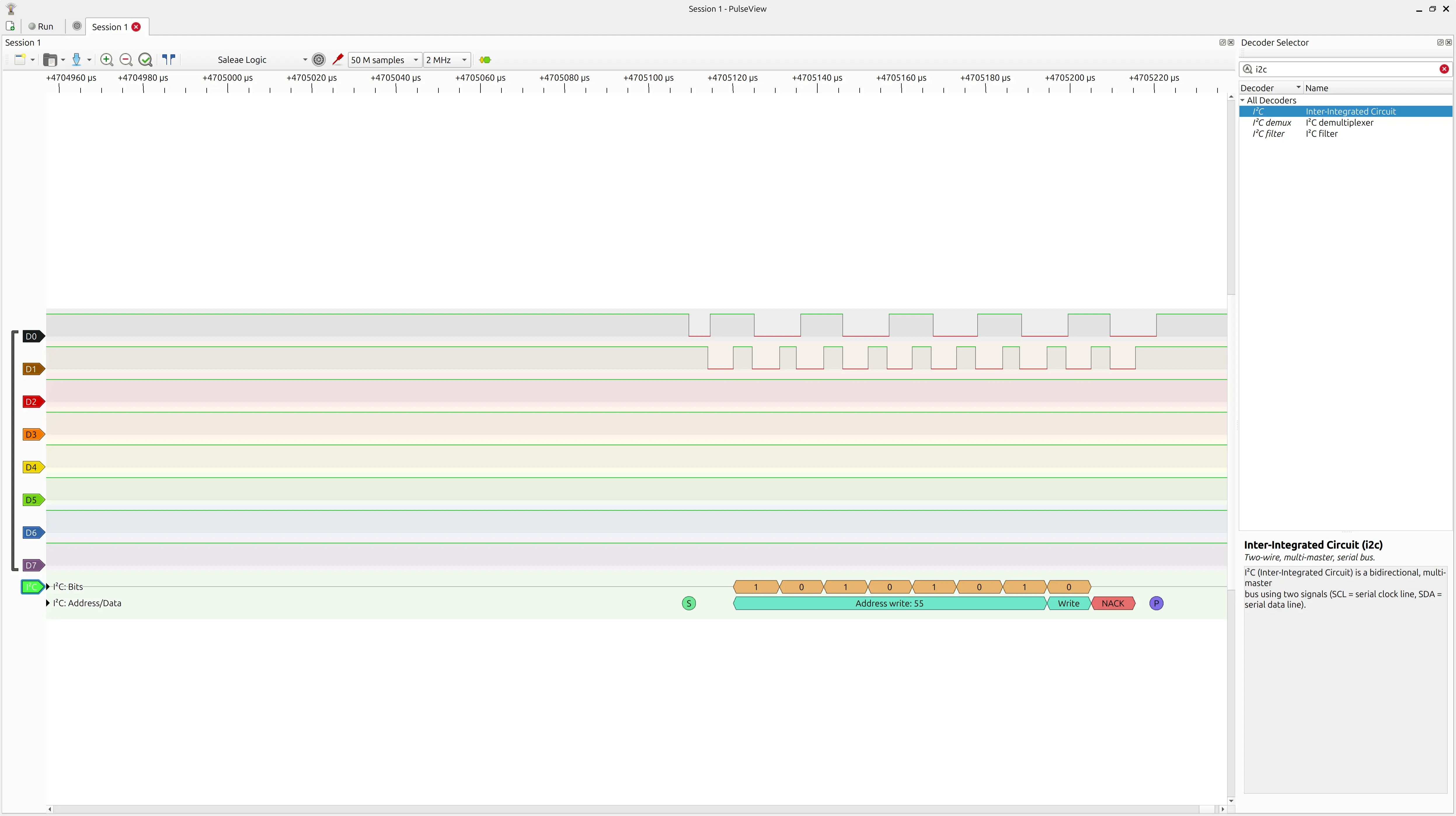
After much hair pulling, wasted hours and AI conversations wondering why, despite seeing signals on the logic analyzer, I was seeing gibberish, I realized I was using a sample rate of 20 kHz, while the default of the I2C protocol on these boards runs at 100 kHz. 🤦
Given the under sampling, the protocol decoder would interpreter it as gibberish.
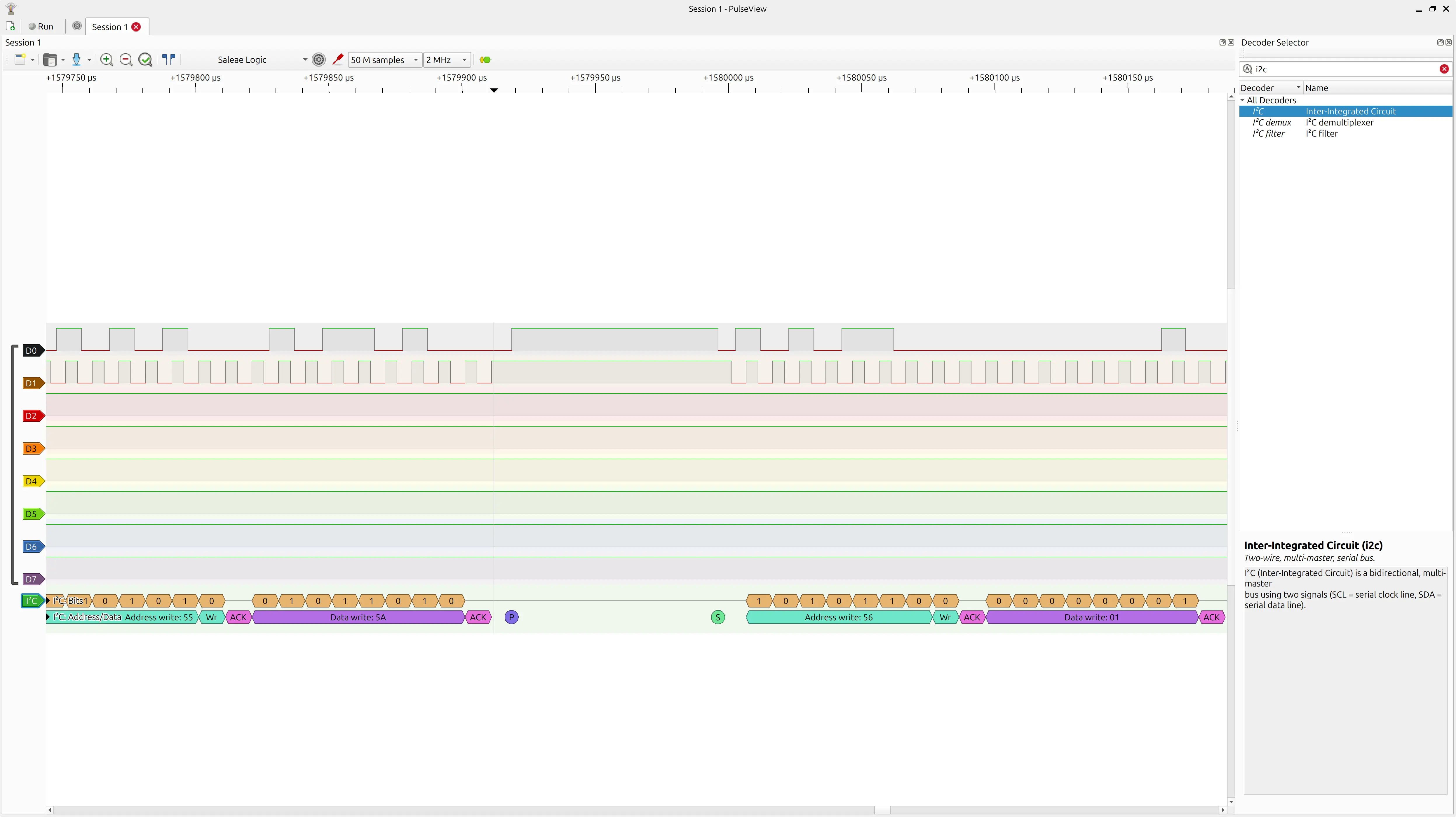
Once I changed the sample rate to 2 MHz and collected 50 M samples, I was able to see the addresses that WireScan was probing, so I switched back to my code and finally saw the 0x55 address that I had coded:
Problem 3
Once I established the sender was correct, I needed to establish why the slave was not responding, so there was a lot of connecting, reconnecting, plugging in the logic analyser at different points, unplugging the Xiaos from their boards and connecting them directly to each other to exclude problems in the boards. Nothing helped.
At some point I wondered if the ESP32C6 understood I2C at all, or there was some problem with this Xiao or the library, so I decided to invert the roles, and make the ESP32C6 the master and the RP2040 the slave.
Surprise, surprise, communication was established and WireScan could finally see the device on the other hand 🚀
I investigated further and found this post. Basically “I2C Slave Mode is not supported on the ESP32-C6 using the Arduino Wire library.” 😭
This is quite misleading as the code compiles and does not return errors when running. It just doesn’t work 🙄
Problem 4
I could have given up on the ESP32C6, but since I didn’t really need any of its wireless capabilities, it’s basically another Xiao with similar pins. So I switched the ESP32C6 to the input board, and the RP2040 to the output board.
I tried the WireScan code and it didn’t work 😱
It worked fine out of the board but not in it 🤔
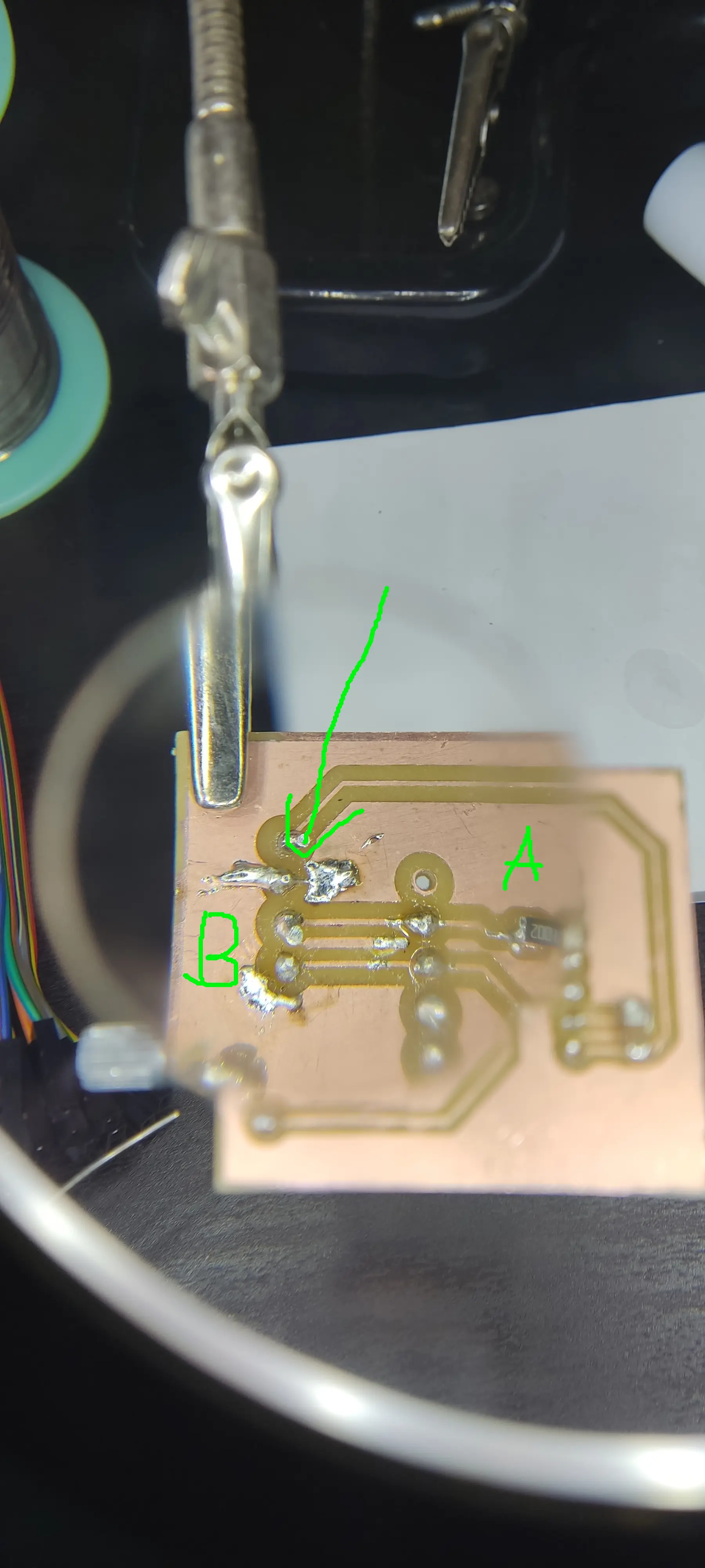
I investigated and with all the experiments and cable connection and disconnection the connector had wobbled and the soldering had come loose.
So I applied a bit of glue to prevent further wobbling, and applied the solder iron again on the connector wires. The misleading part was that when I was testing it with the multimeter once again, the pressure from the probes would make it make contact, leading me to think that everything was OK, but it wasn’t.
Eventually looking it with a clock-worker magnifying glass, I was able to spot the problem.
Problem 5
You would think I my problems were over, but nooooo.
I loaded the sketch from the input week (removing the NeoPixel parts, since it does not have it).
The potentiometer would not read correctly. Despite turning the knob, the value read barely moved. The symptom pointed out to the analog pin being open (not connected) or having no ground reference.
I tested tracks, pins, connections, etc, all over again, and it seemed fine. I swapped again the Xiao and the problem was the same, so the problem was probably on the board.
After a few more hours investigating, I realized the GND fill had 2 areas and the GND pin on the chip and the larger area, were only connected through a small pin connection, so I temporarily joined both areas with a DuPont wire, and now the reading was correct. For some reason that connection had come undone and so I applied more solder to make sure both areas connected.
Finally the code for the input week worked. However, the range of values for the analog pin with the RP2040 used to be roughly 0-1024, whereas with the ESP32C6 was 0-900 🤔
I didn’t investigate this further and just adapted to the new range.
Second try
So, adapting the code for the new master with the ESP32C6, I settled on this:
#include "Wire.h"

#define I2C_SLAVE1_ADDR 0x55 // stepper
#define I2C_SLAVE2_ADDR 0x56 // pico

uint32_t i = 0;

#define SAMPLES 50

// Initialize the NeoPixel object

void setup() {
  delay(2000);
  analogReadResolution(10);
  Serial.begin(115200);
  Serial.println("I2C Master Initializing");

  Wire.setPins(D4,D5);
  Wire.begin();
  Serial.println("I2C Master Initialized");
}

void send(uint8_t addr, uint8_t value){
  Wire.beginTransmission(addr);
  Wire.write(value); // Sends exactly 1 byte
  byte error = Wire.endTransmission();
  if (error == 0) {
    Serial.print("Sent value: ");
    Serial.println(value);
  } else {
    Serial.print("Error sending: ");
    Serial.println(error);
  }
}

void loop() {
  float averageValue = 0;

  // Smoothing loop
  for (int i = 0; i < SAMPLES; i++) {
    averageValue += (float) analogRead(A0) / SAMPLES;
    delay(1);
  }
  Serial.println((int) averageValue);
  uint8_t txByte = constrain(averageValue / 4, 0, 255); //input was 0-1023, so we just need to downscale to 0-255

  // Threshold logic
  if (averageValue <= 300) {
    send(I2C_SLAVE1_ADDR, 0);
    send(I2C_SLAVE2_ADDR, 0);

  } else if (averageValue >= 600){
    send(I2C_SLAVE1_ADDR, 180);
    send(I2C_SLAVE2_ADDR, 2);
  } else {
    send(I2C_SLAVE1_ADDR, 90);
    send(I2C_SLAVE2_ADDR, 1);
  }

  delay(1000);
}
I created a send function to encapsulate the transmission, and on each loop run, depending on the range of the reading, I send a different message to each slave: for the servo I send an angle and for the 2nd slave, just a number to indicate how a LED should behave.
I have a delay of 1s, because when experimenting, if I sent messages too often I would get NACKs. With 1s in between messages, they were all successful as far as I could tell.
For the servo with the RP2040 I had this:
#include "Wire.h"
#include <Servo.h>

#define I2C_SLAVE1_ADDR 0x55

Servo myservo;  // create Servo object to control a servo

void onReceive(int len) {
  Serial.printf("onReceive[%d]: ", len);
  while (Wire.available()) {
    uint8_t value = Wire.read();
    Serial.print(value);
    int angle = constrain(value, 0, 180);
    myservo.write(angle);
  }
  Serial.println();
}


void setup() {
  Serial.begin(9600);
  myservo.attach(D9,500,2500);  // attaches the servo on pin 9 to the Servo object

  Wire.onReceive(onReceive);
  Wire.begin((uint8_t)I2C_SLAVE1_ADDR);
}

void loop() {
}
I used the Servo library again, since it was available for this platform. The loop does nothing because we programmed the board with an interrupt handler which is the onReceive function.
And finally for the Pico W dev board, I wrote this:
#include "Wire.h"

#define I2C_SLAVE2_ADDR 0x56

volatile uint8_t value = 1;

void onReceive(int len) {
  while (Wire.available()) {
    value = Wire.read();
  }
}


void setup() {
  pinMode(LED_BUILTIN, OUTPUT);
  Wire.setSDA(0);
  Wire.setSCL(1);
  Wire.onReceive(onReceive);
  Wire.begin((uint8_t)I2C_SLAVE2_ADDR);
}

void loop() {
  if (value == 0){
    digitalWrite(LED_BUILTIN, LOW);
  } else if(value == 2) {
    digitalWrite(LED_BUILTIN, HIGH);
  } else {
    digitalWrite(LED_BUILTIN, LOW);
    delay(200);
    digitalWrite(LED_BUILTIN, HIGH);
    delay(200);
  }
}
Since the Pico has multiple I2C possibilities, I made it explicit which pins to use.
Also it’s recommended not to use delays inside the interrupt handler, but since I wanted to use it for blinking the LED, I did it slightly different: The onReceive just saves the last value, which is used later inside the loop function.
According to the message received the built in LED will be either on, off, or blinking.
Here we can see in PulseView the the decoded I2C protocol sending the 90 angle message to the servo board and the 1 message to the pico board:
Hero shot
Finally here’s a video with all the setup:
For “bus” connection everything is connected with DuPont wires through a breadboard.
Both the input board and the pico baord are powered through USB. The Servo board is powered with 5V through the cable coming from the input board.
The logic analyzer is also connected so I could observe the protocol.
As I turn the knob we can see the servo moving from 0 to to 90 and then 180 degrees, whereas the Pico switched the LED from being off, to blinking to on.
Learnings
I think this was mostly a lesson in resilience and not giving up ! 😅
I learned about using PulseView, how I2C needs an ACK before sending the payload data.
Also about timing protocols and “flooding” the receiver with too many messages.
Although I didn’t use this mode, one can also have the Master requesting data from the slaves.
Files
Please refer to week 9 and week 10 for the input (potentiometer) and output (servo) boards respectively