Datasheet
I planned to use a camera for my final project, so after a bit of research, I found that there’s a combo that includes the ESP32-S3 and a camera called ESP32 Sense
The main specs are:
XIAO ESP32-S3 Sense Technical Specifications
| Feature | Specification |
|---|---|
| Processor | ESP32-S3R8 Xtensa® 32-bit LX7 Dual-Core, up to 240 MHz |
| Wireless | 2.4GHz Wi-Fi (802.11 b/g/n), Bluetooth 5.0, BLE, and Mesh |
| Memory | 8MB PSRAM (on-chip) and 8MB Flash (on-board) |
| Camera | Detachable OV2640 (1600 x 1200 resolution) or OV3660 (2048 x 1536) |
| Audio | Integrated Digital Microphone (on the expansion board) |
| Storage | On-board microSD Card Slot (supports up to 32GB FAT) |
| I/O Pins | 11x GPIO (all PWM capable), 9x ADC |
| Interfaces | 1x UART, 1x I2C, 1x I2S, 1x SPI |
| Programming | USB Type-C (Native), supports Arduino, MicroPython, ESP-IDF |
| Power Input | 5V via USB-C or 3.7V via Battery pads |
| Charging | Built-in Lithium battery charging management (100mA charge current) |
| Dimensions | 21 x 17.5 x 15 mm (including the sense expansion board) |
| Deep Sleep | ~ 3mA |
For the camera usage I plan, here are some interesting power requirements:
Type-C:
- Average power Consumption: 5V/~140mA
- Peak power consumption(Image Capture): 5V/~347mA
Battery:
- Average power Consumption: 3.8V/~155mA
- Peak power consumption(Image Capture): 3.8V/~366mA
Also for the Wi-Fi Enabled Power Consumption usage, this should also be of interest:
- Active Mode: 110 mA (with expansion board)
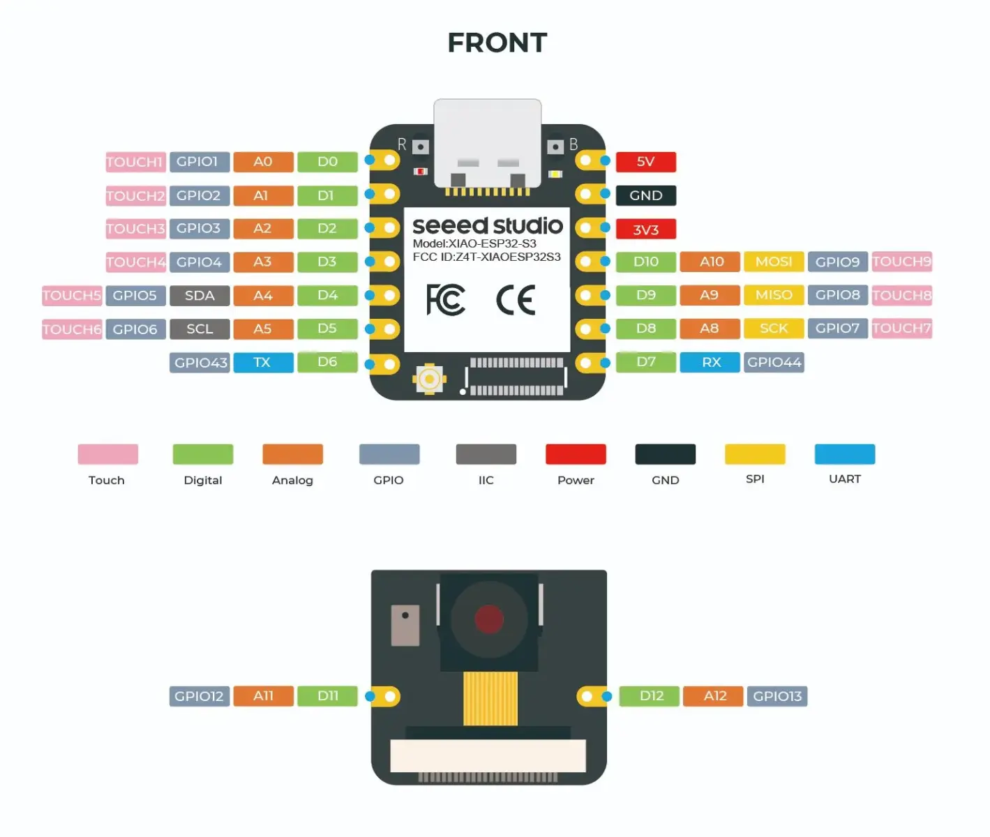
The pins functions are multiplexed, and can be configured for different functions.
Here’s how they are set:
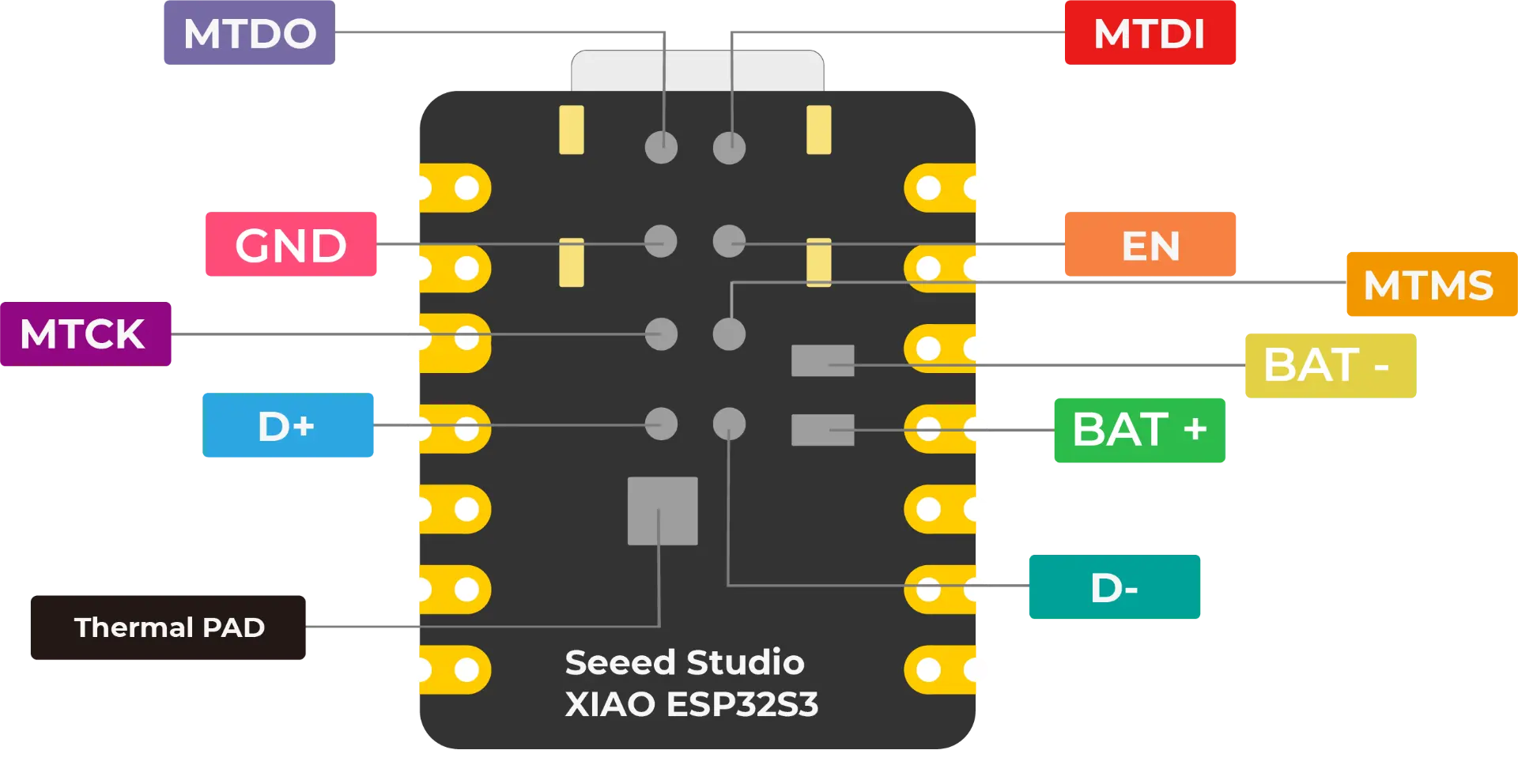
And from the back:
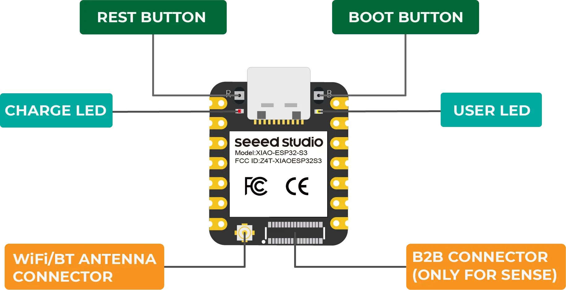
And the buttons and other connectors:
I searched for the datasheet for the ESP32-S3, and while the technical reference has a staggering 1531 pages 🤯, the regular datasheet only has 87 pages 😌
I skimmed through it and picked up a couple of interesting tidbits which could prove useful in the future:
Ultra-Low-Power Coprocessor (ULP)
The ULP coprocessor is designed as a simplified, low-power replacement of CPU in sleep modes. It can be also used to supplement the functions of the CPU in normal working mode. The ULP coprocessor and RTC memory remain powered up during the Deep-sleep mode. Hence, the developer can store a program for the ULP coprocessor in the RTC slow memory to access RTC GPIO, RTC peripheral devices, RTC timers and internal sensors in Deep-sleep mode. ESP32-S3 has two ULP coprocessors, one based on RISC-V instruction set architecture (ULP-RISC-V) and the other on finite state machine (ULP-FSM). The clock of the coprocessors is the internal fast RC oscillator.
Since I plan to control some motors, this could also be useful:
Motor Control PWM (MCPWM)
ESP32-S3 integrates two MCPWMs that can be used to drive digital motors and smart light. Each MCPWM peripheral has one clock divider (prescaler), three PWM timers, three PWM operators, and a capture module. PWM timers are used for generating timing references. The PWM operators generate desired waveform based on the timing references. Any PWM operator can be configured to use the timing references of any PWM timers. Different PWM operators can use the same PWM timer’s timing references to produce related PWM signals. PWM operators can also use different PWM timers’ values to produce the PWM signals that work alone. Different PWM timers can also be synchronized together
While it’s good to know the overall characteristics of the chip, most of these features are to be consulted when you need them, and users don’t usually have to read a full novel before they can use the microcontroller 😉