Individual assignment
Intro
I was inspired by Quentin’s molding of a Escher lizard tile and since Portugal has a strong tradition of making tiles, that span centuries and is one of the highlights that tourists enjoy when visiting our country, I thought about doing some too.
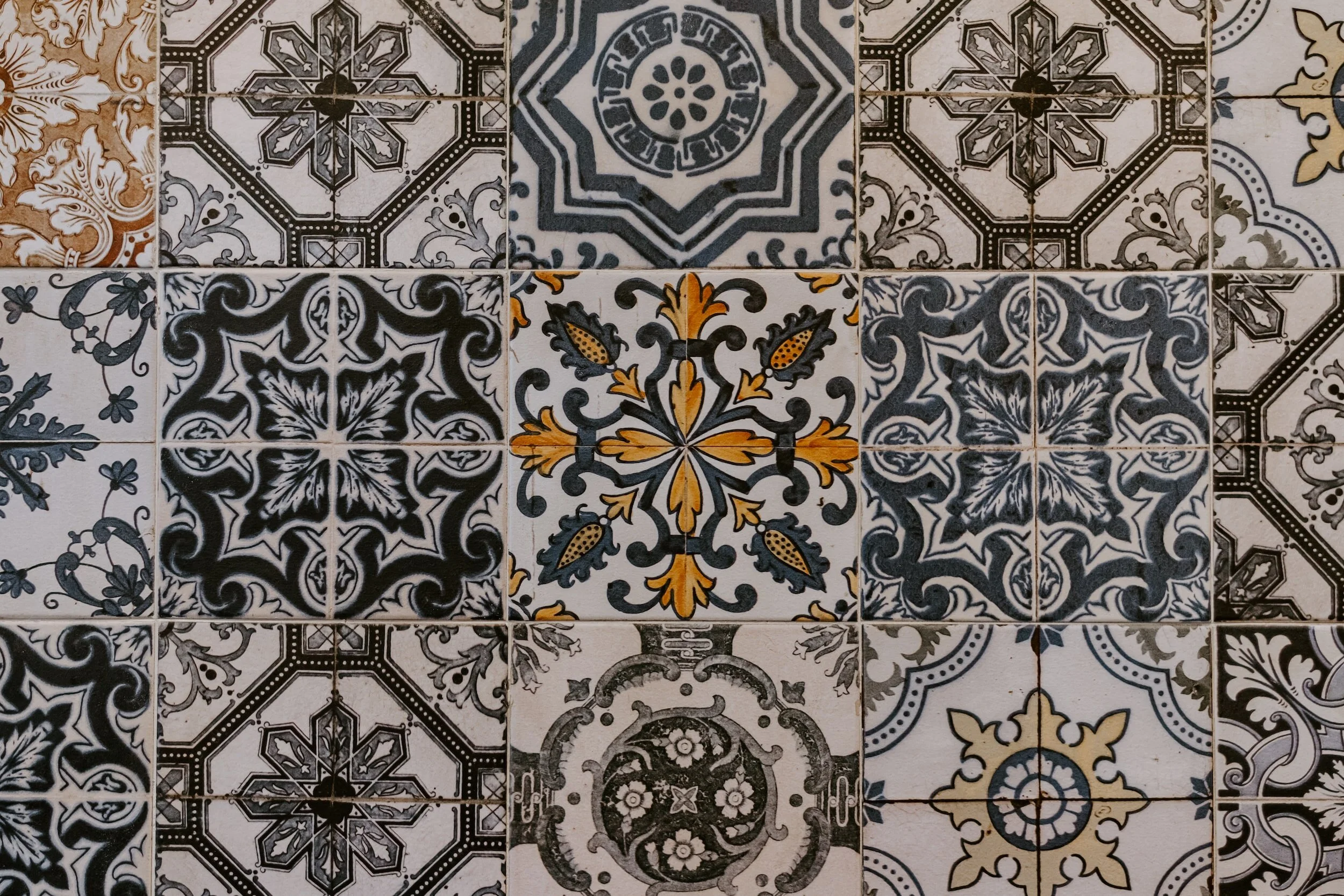
However, Quentin’s tiles reminded me of a similar, but somewhat opposite concept: a relatively recent discovery about aperiodic tiles.
Aperiodic Monotile: The “Einstein” of Tiling
An aperiodic monotile, also known as an einstein is a single geometric shape that can cover an infinite plane without gaps or overlaps in a pattern that never repeats. The term comes from the German phrase ein Stein, meaning “one stone,” rather than referring to the physicist Albert Einstein.
In 2022, retired printing engineer David Smith discovered the first true einstein, a 13-sided polygon he nicknamed “the Hat.” He collaborated with mathematicians and computer scientists to prove that this shape, along with an infinite family of related shapes (including “the Turtle” and “spectres”), creates aperiodic tilings. This discovery solved a 50-year-old mathematical problem, proving that a single prototile can enforce non-periodicity, a feat previously thought impossible or requiring multiple tile shapes.

Design
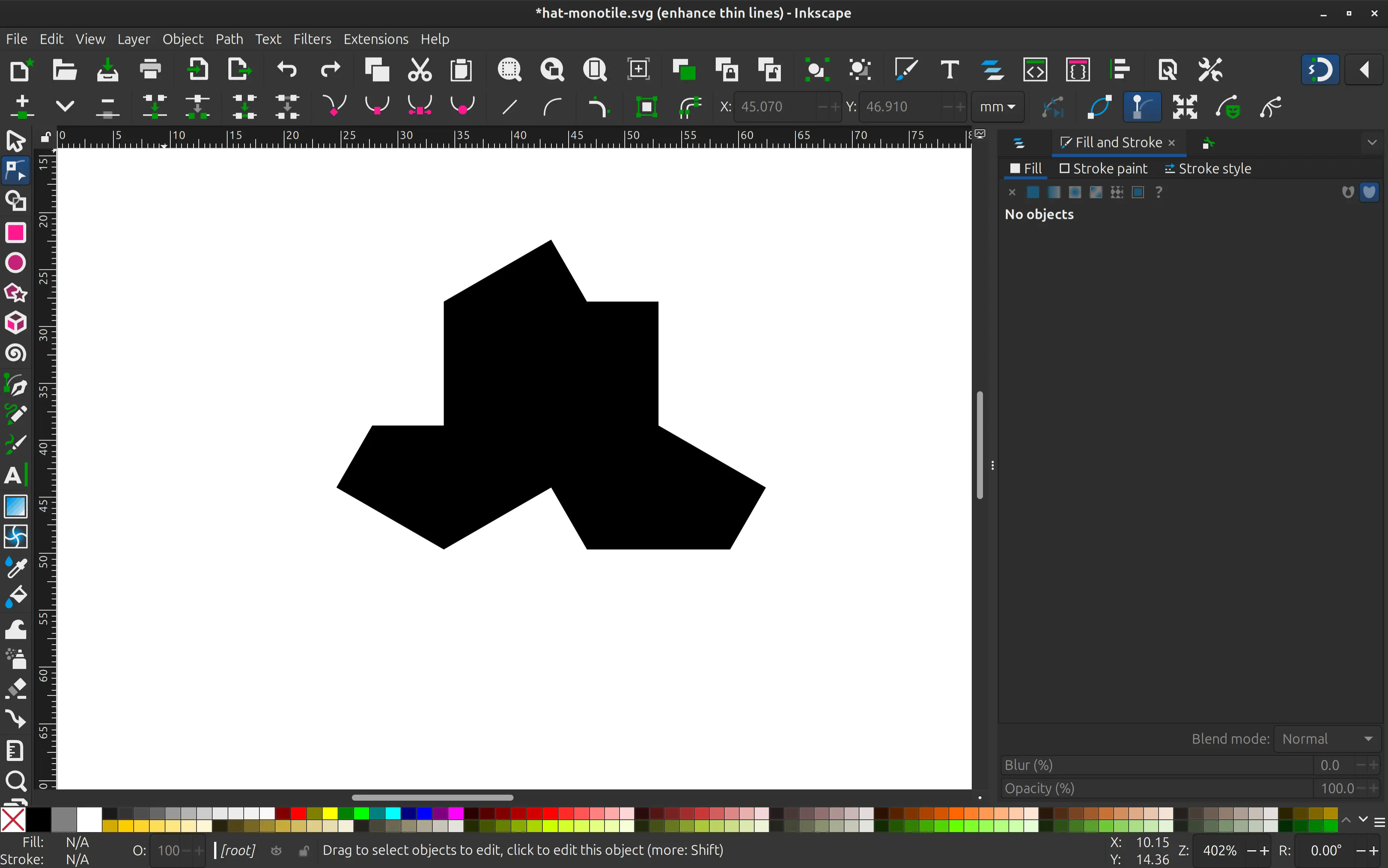
Since the shape is already known, I downloaded an SVG with it an imported it into inkscape:
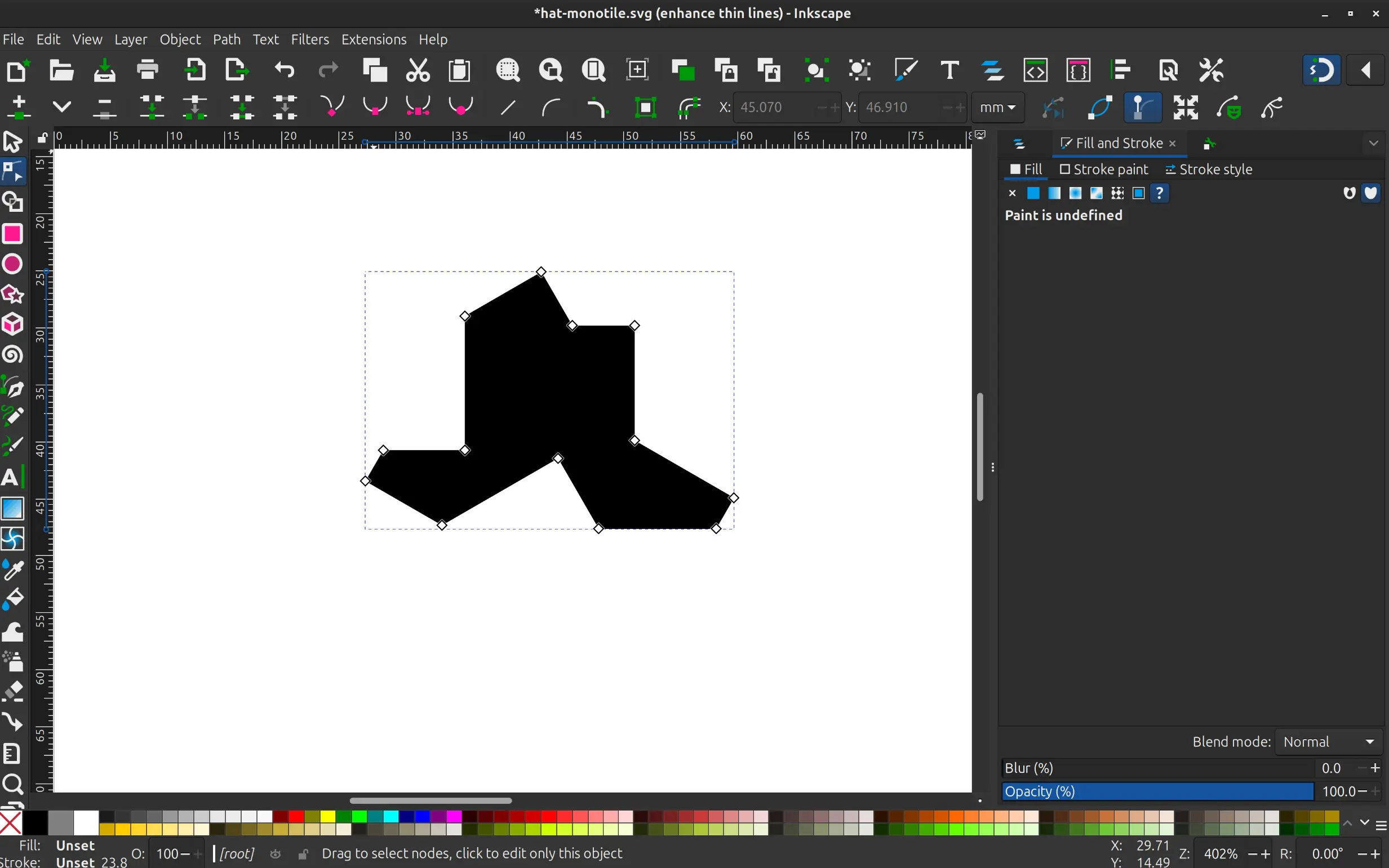
Following the advice of instructor André Rocha, I made an inset of the shape to make space for the grout, when they are put together. Here the offset is exaggerated just for illustration purposes. In reality I made it 1 mm, but that would not be visible in the screenshot.
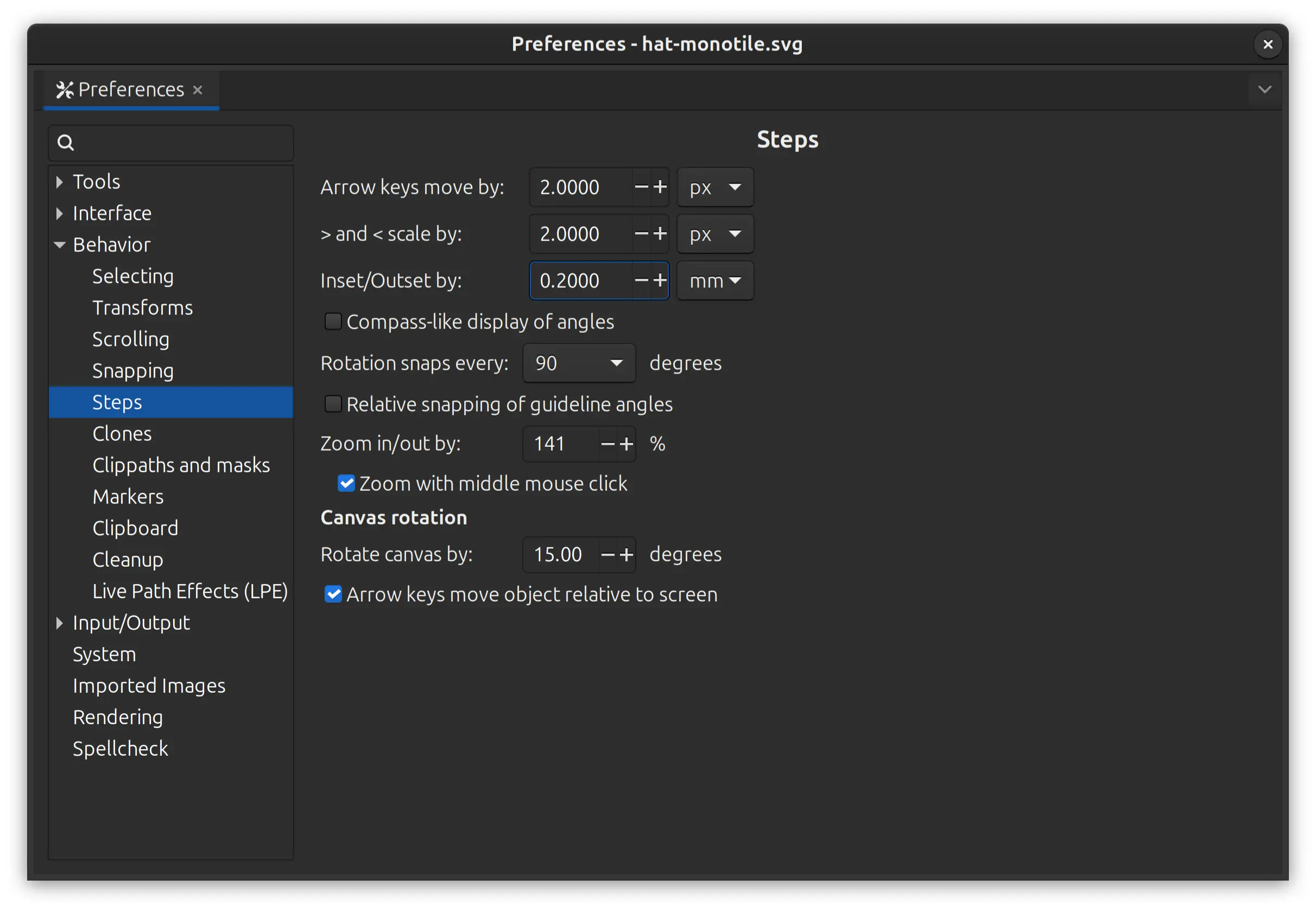
To be able to control the offset in inkscape, I go to Preferences -> Behavior -> Steps and set an Inset/outset step smaller than I need, and adjust accordingly:
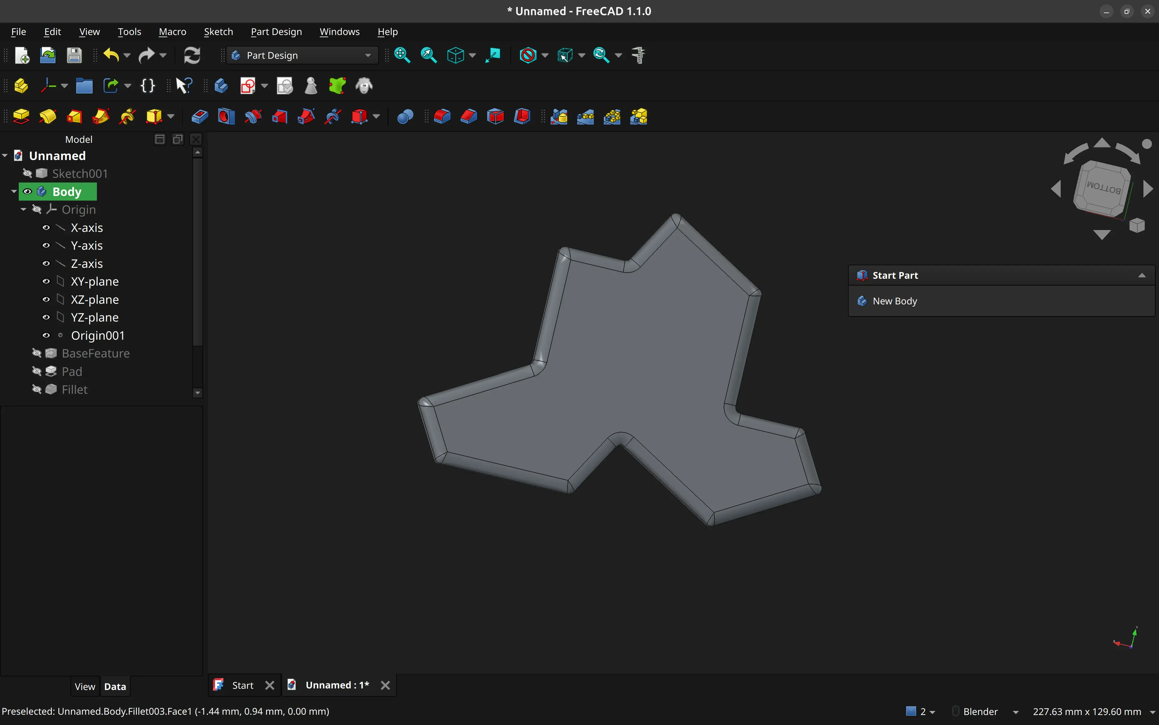
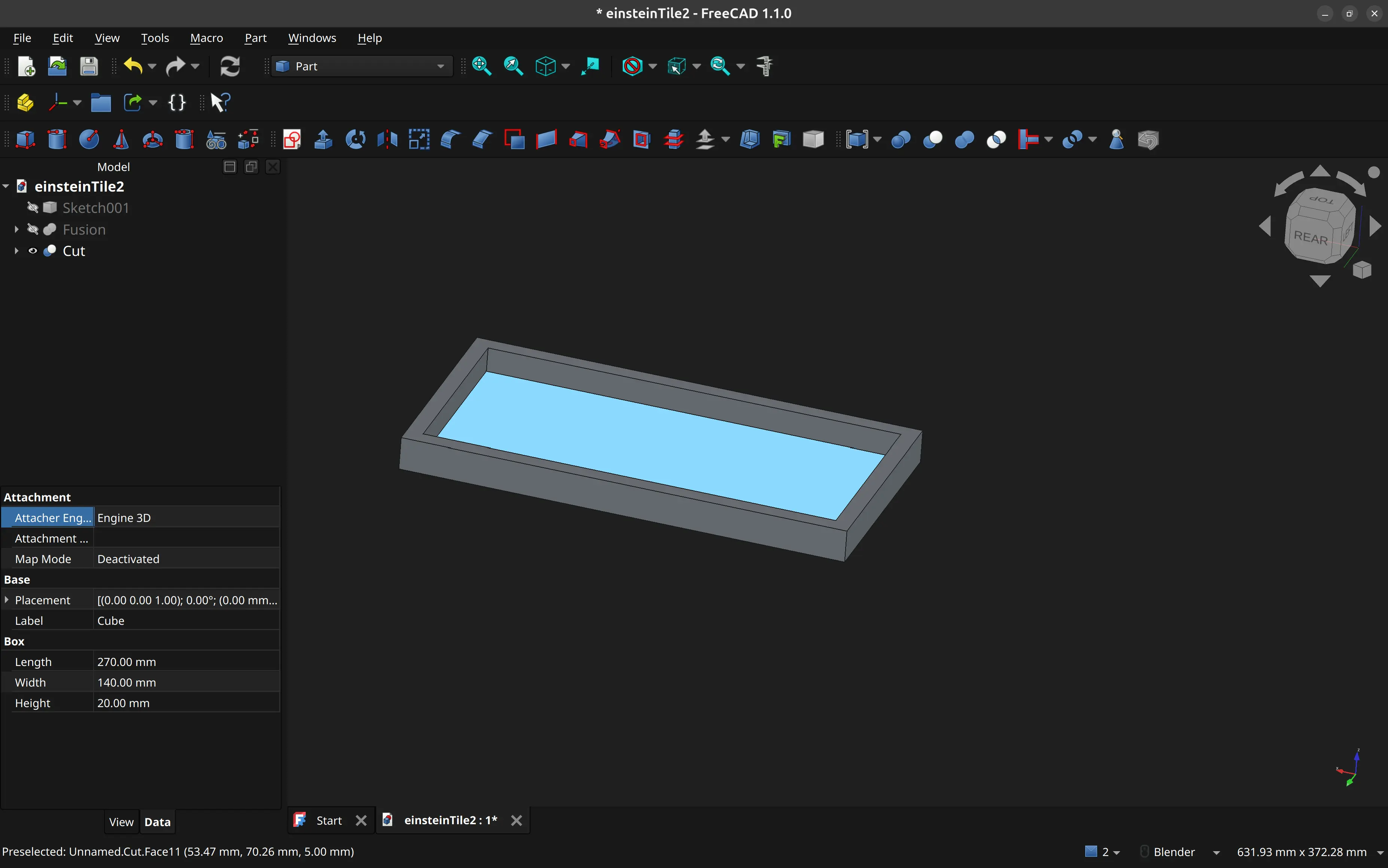
I then import it into FreeCAD, extrude it, and create some fillets all around for easier unmolding.
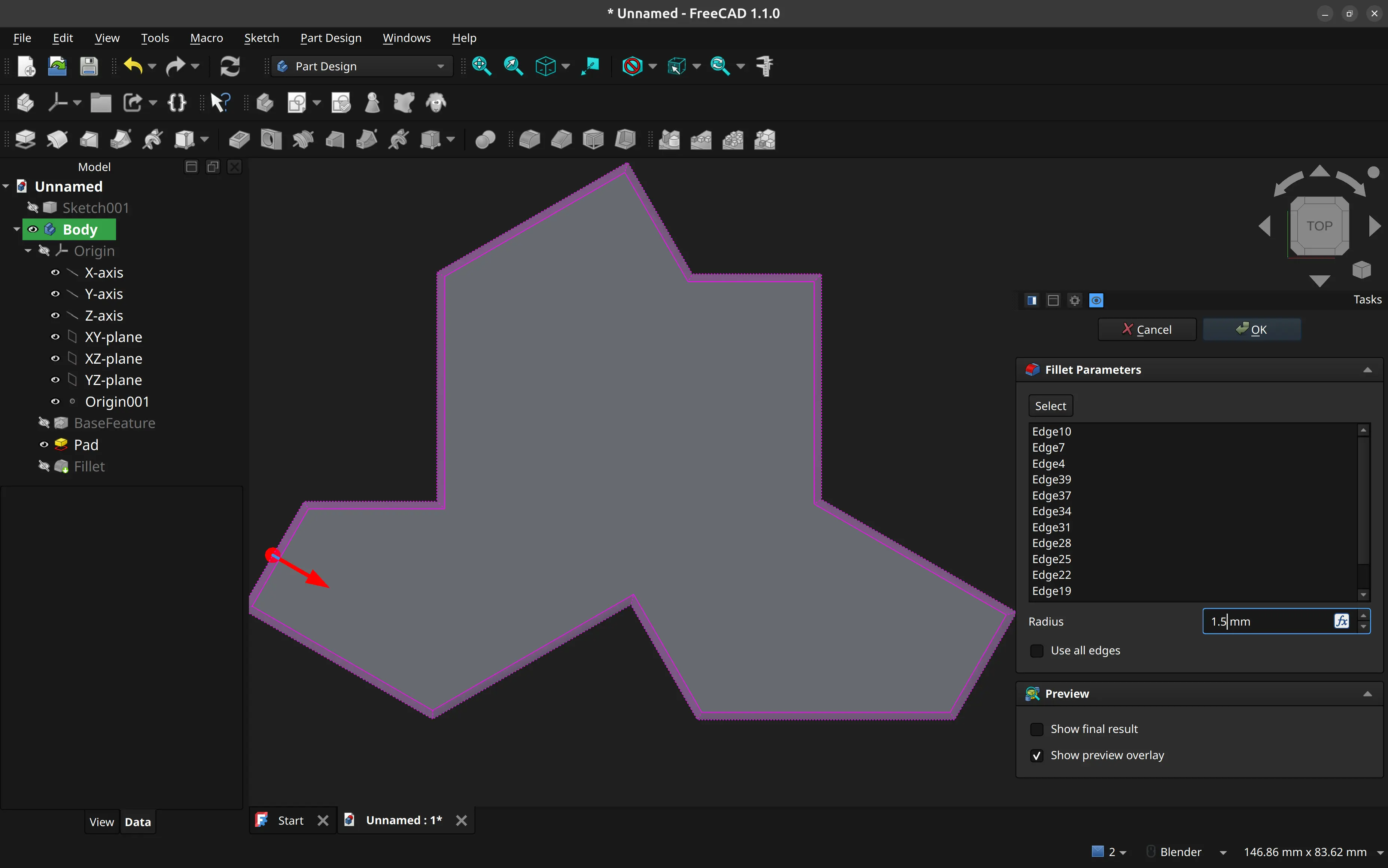
Here’s the basic shape:
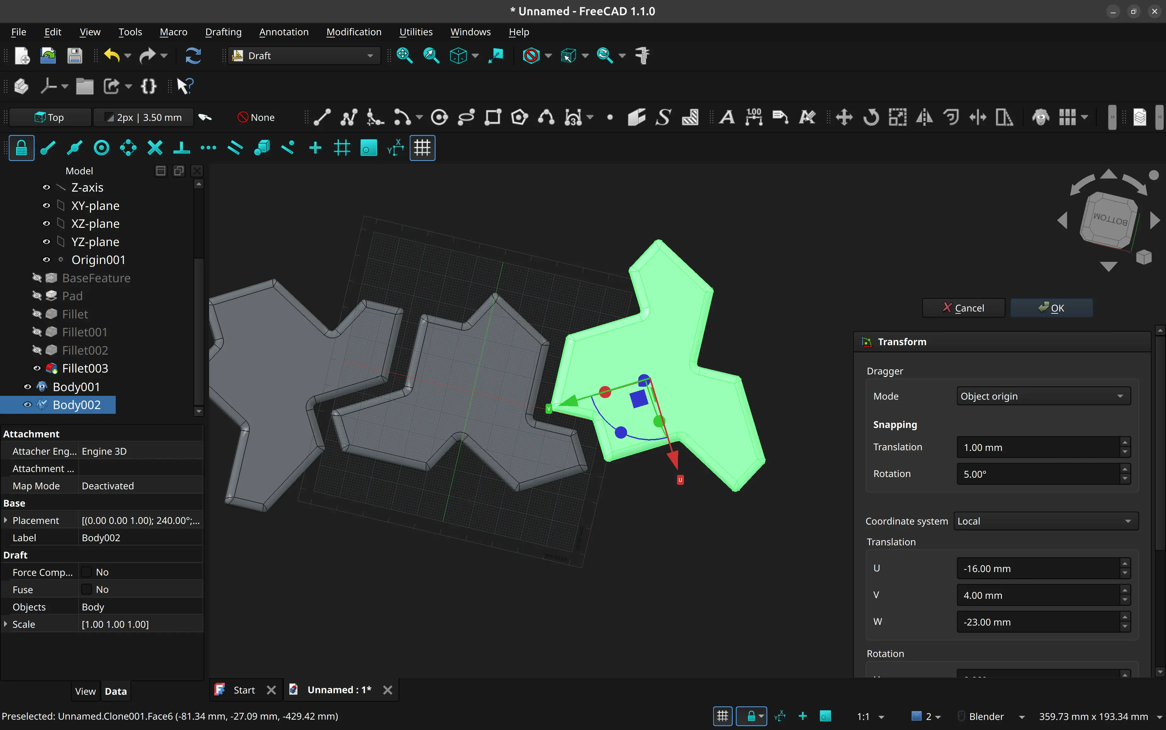
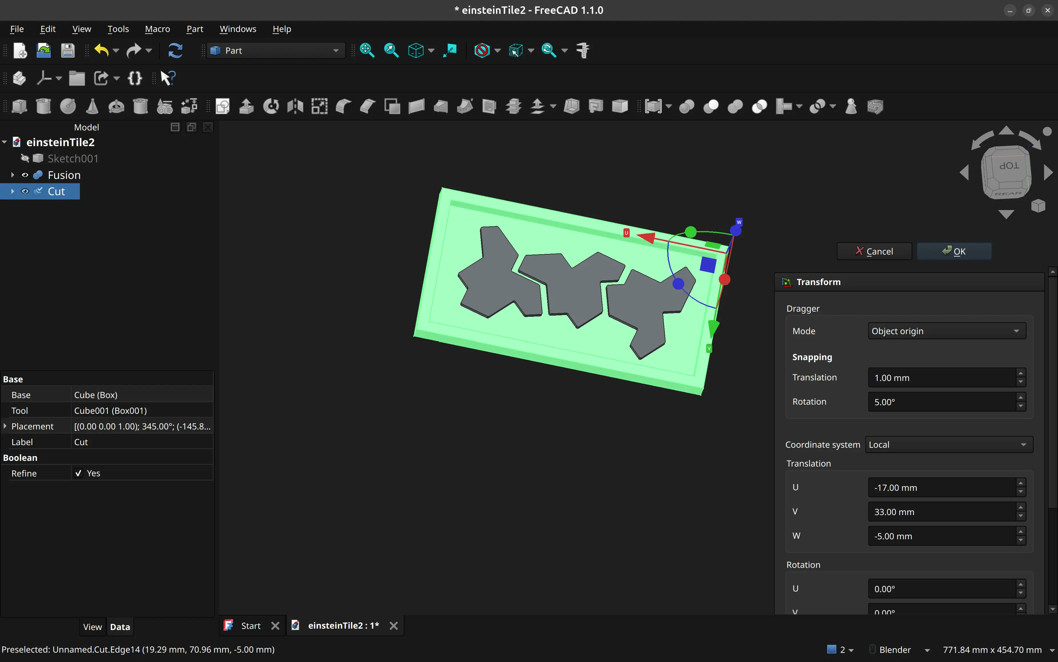
I then copy and rotate the copies so that they almost fit, so that I can create a mold for more than one:
I then design a bounding box to hold the silicon.
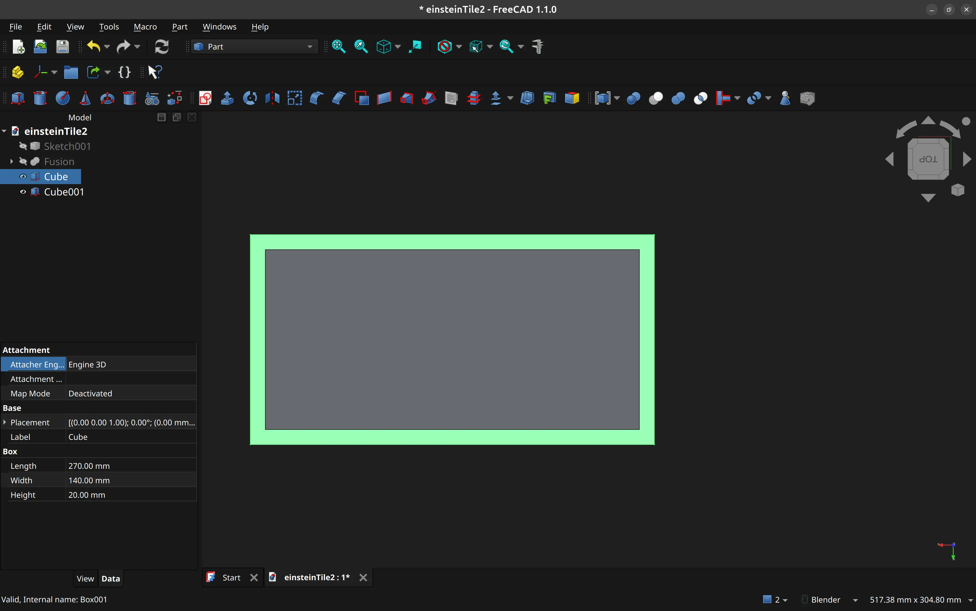
I do the proper extrusions:
And then I combine both.
I then export the design as a step file.
While I would like to do the CAM step in FreeCAD too, that is not currently possible because our CNC machine requires running a post processor that is only available for Fusion 360, which is not available for Linux.
Since instructor André Rocha was available I handed over the step file to him, and he set the toolpath, ran the post processor and exported the nc file on his Mac.
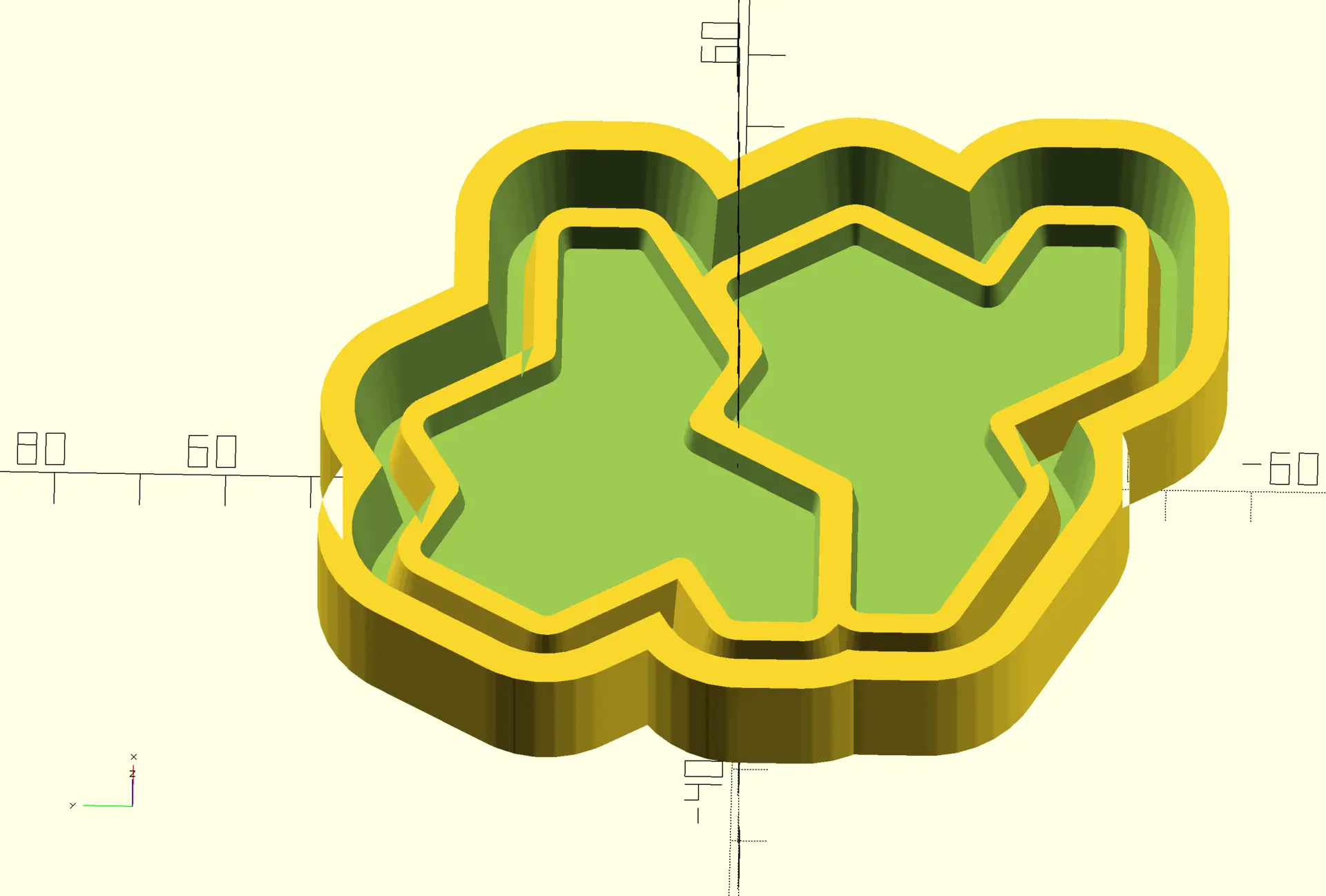
However when looking at my design, he felt we could save some silicon mold, and instead of using my square bounding box, he replaced it with something that looks more like an outline.
That’s the one we ended using in the CNC machine.
Making the master mold
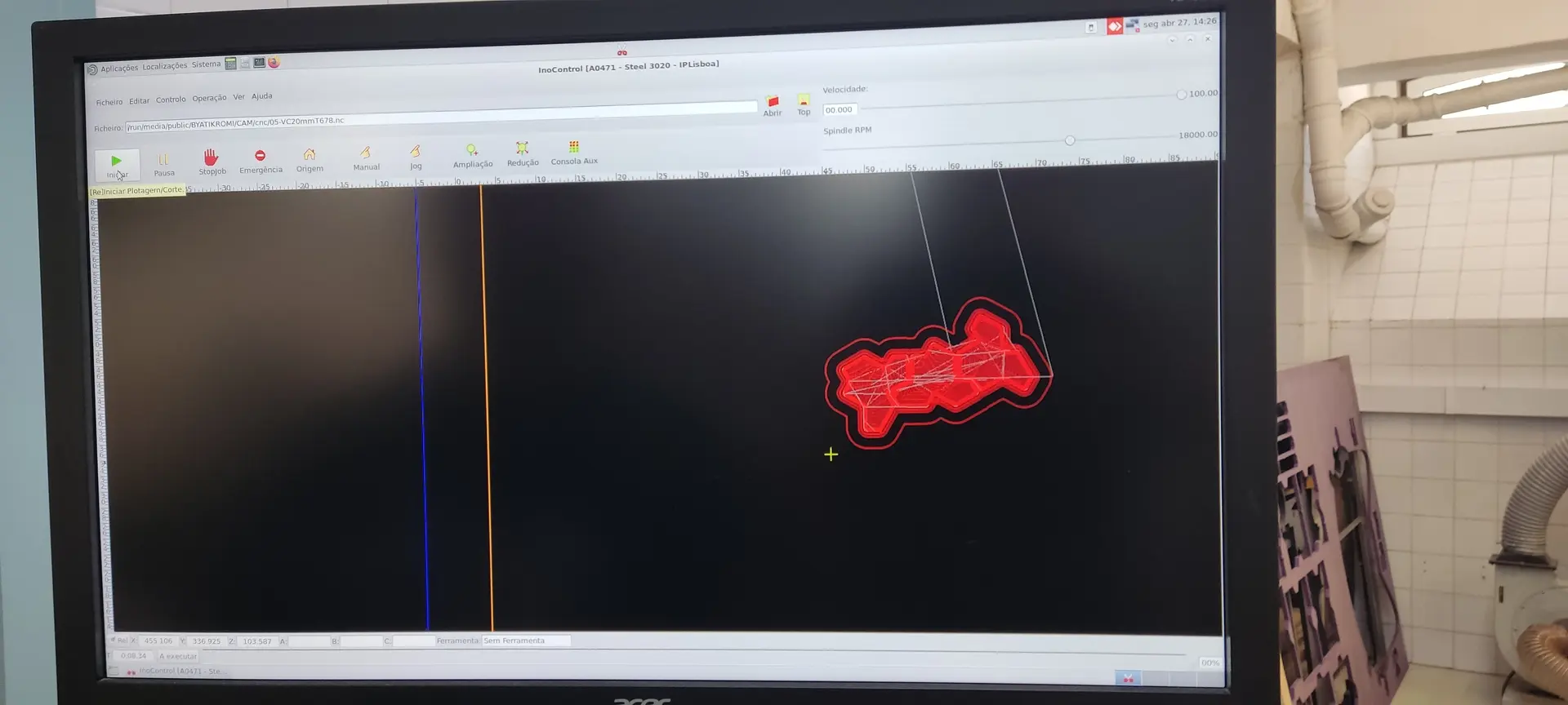
We uploaded the nc file to the CNC software, set the correct origins on the board we had placed and secured there and ran the program:
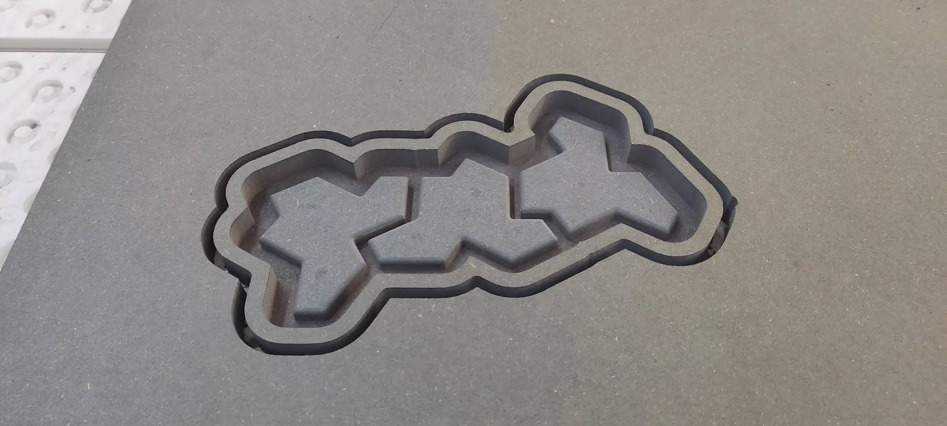
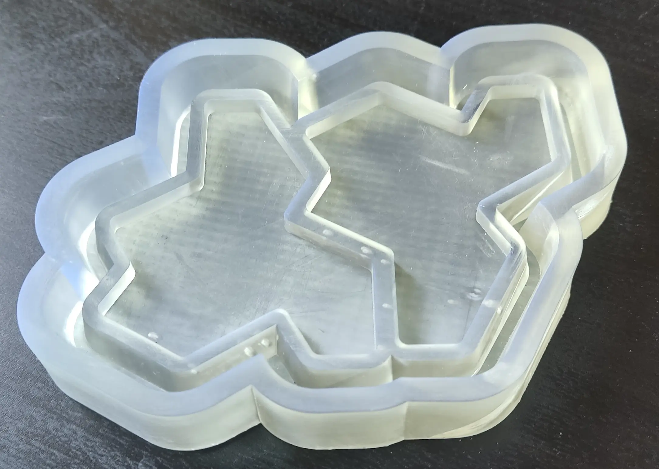
This is what it looks like after all the milling:
Making the negative
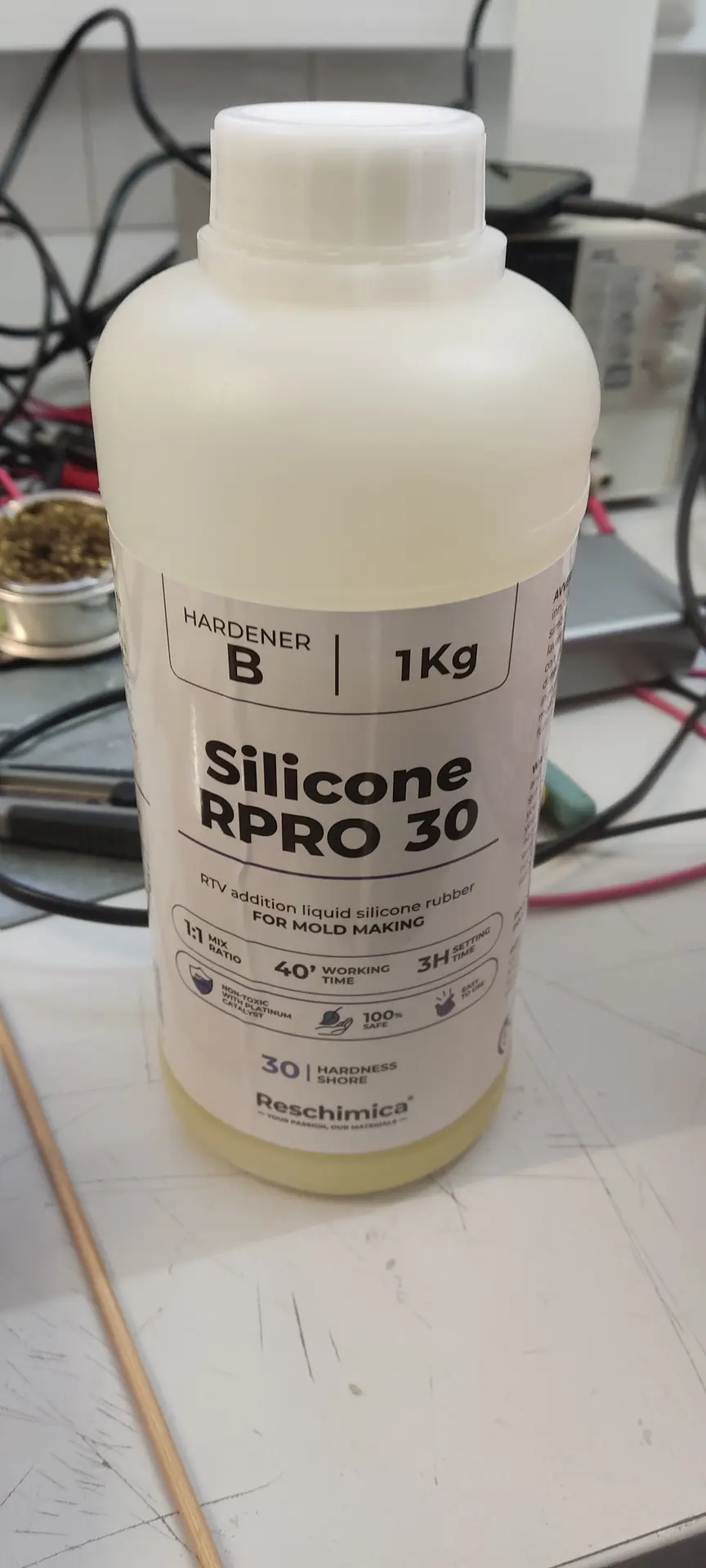
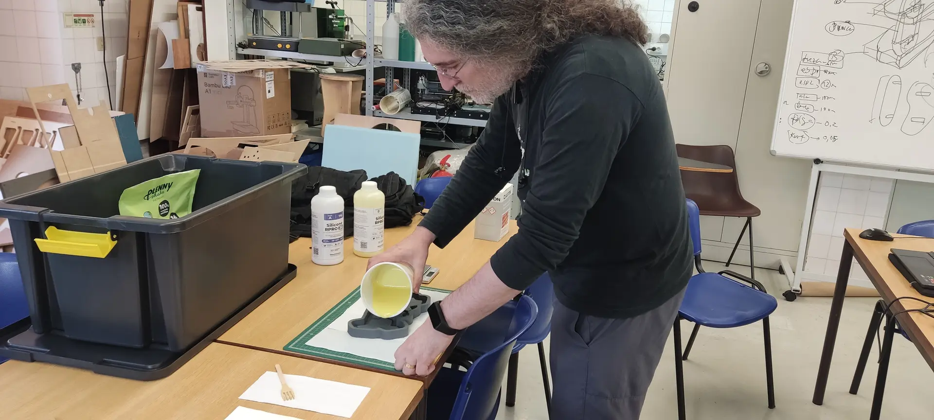
We used this brand of silicon which comprised of 2 different liquids that I mixed in equal proportions:
Once mixed, I carefully poured the mix into the master mold:
After one day of drying I removed the mold.
I needed to use the tool to lift one end of it, but once that was out, the rest came out nicely:
Despite me washing the silicon mold, we see that it picked up some particles:
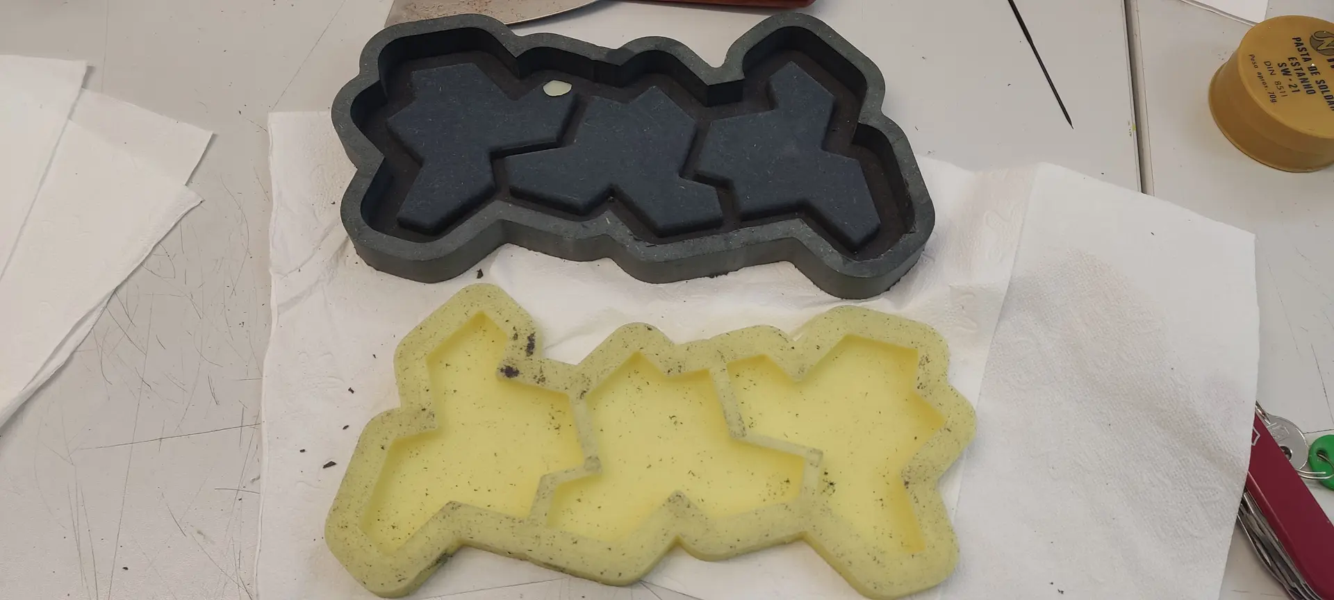
André mentioned it should not be a problem, because they now became part of the mold and would not transfer to the cast, which was accurate.
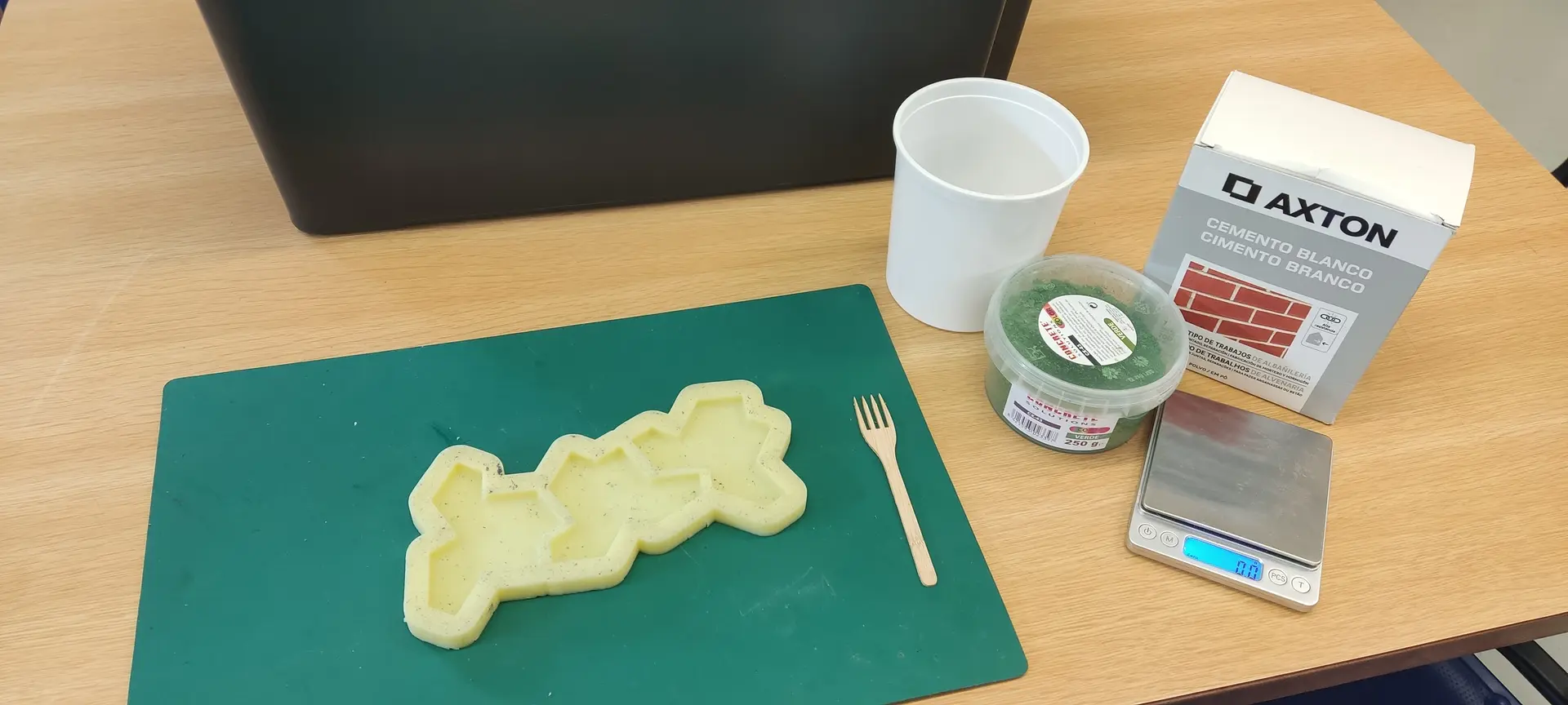
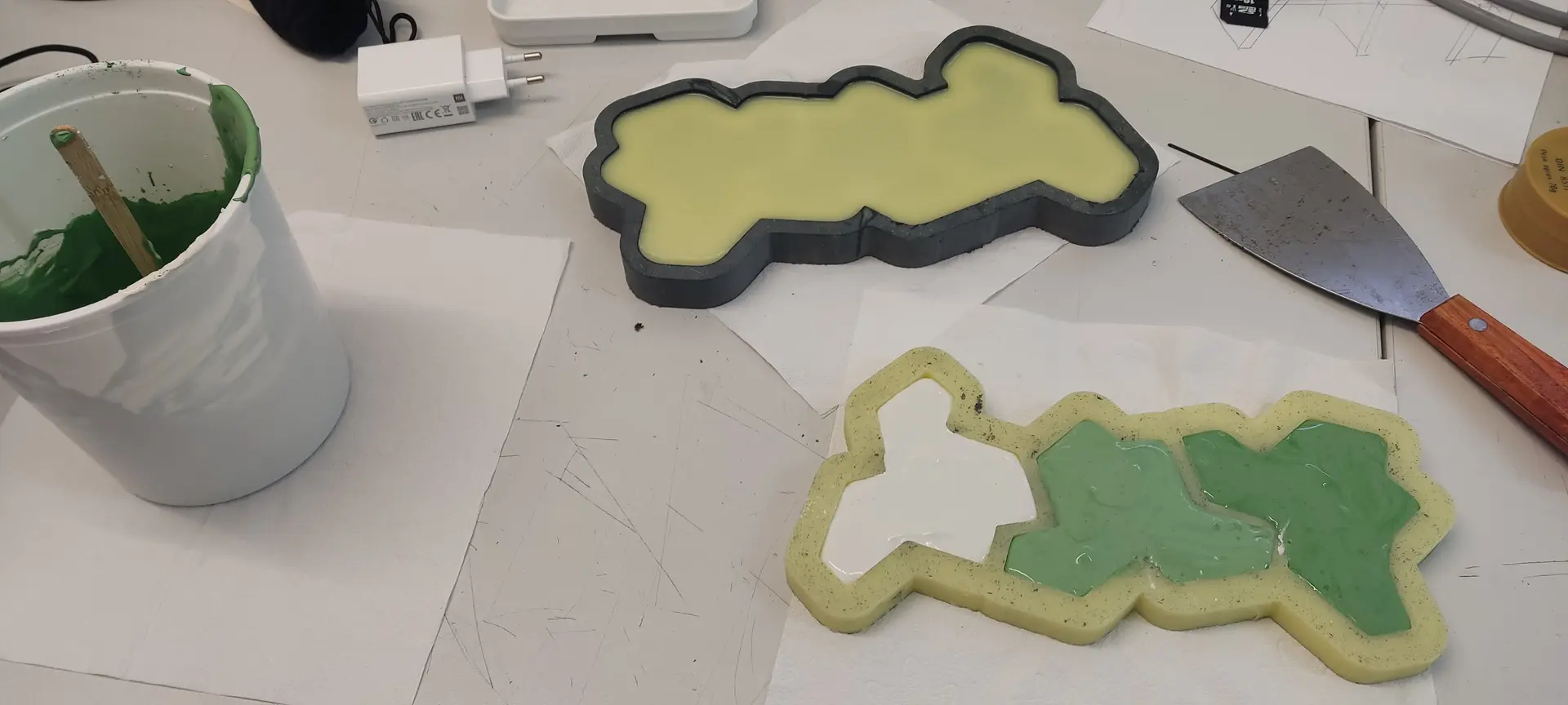
I set everything needed and use some white cement for the cast:
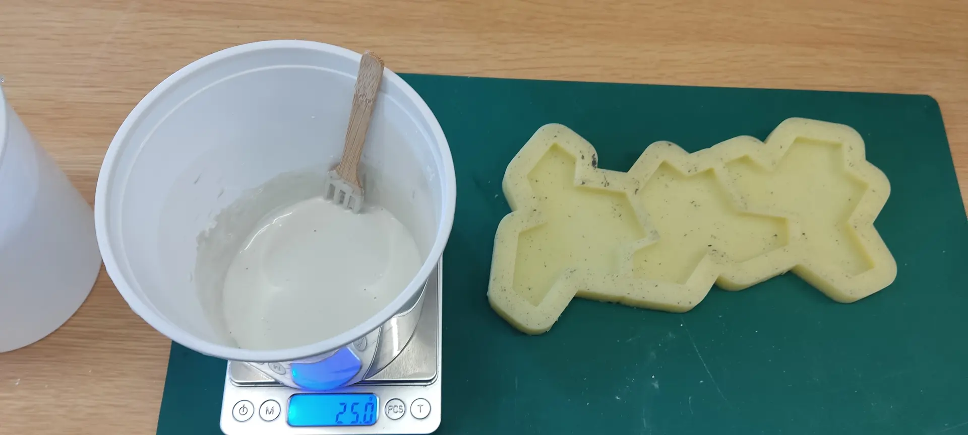
The packaging recommended something like 1 part water to 3 parts cement, but I find that leads to a mixture that is not liquid at all, so I end up pouring more water until I achieve a yogurt like consistency. That’s about twice as much water leading to a 2 parts water to 3 parts cement.
André had suggested adding some color also, so I purchased some appropriate green pigment to try:
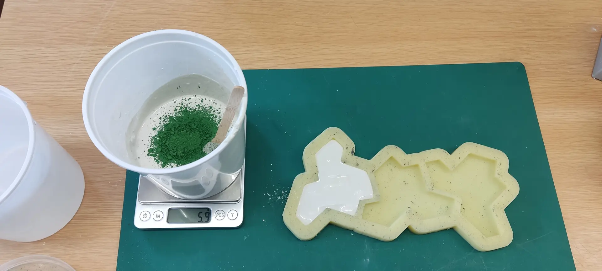
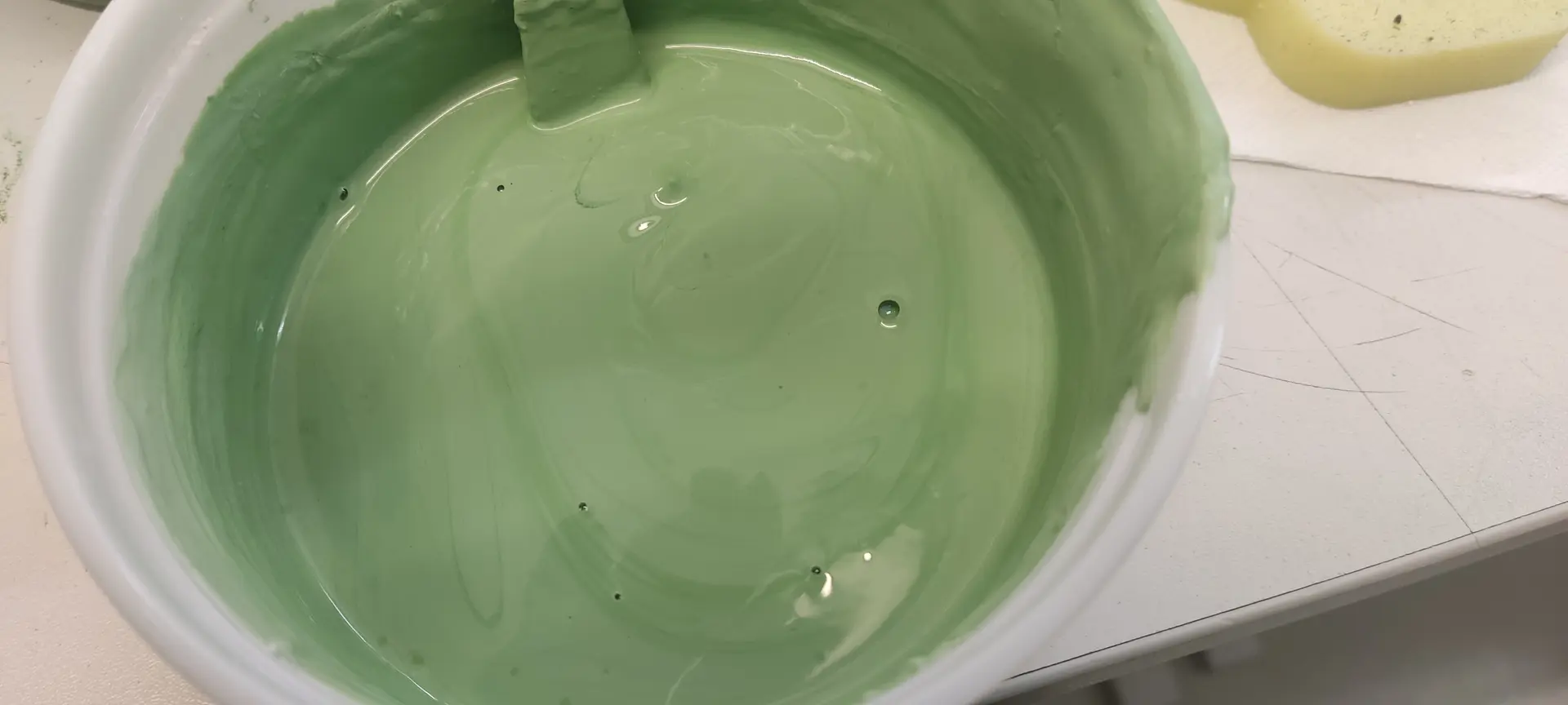
I mix everything and notice that the recommended proportions lead to a already quite green result. I probably should have started with a lot less than the recommendation.
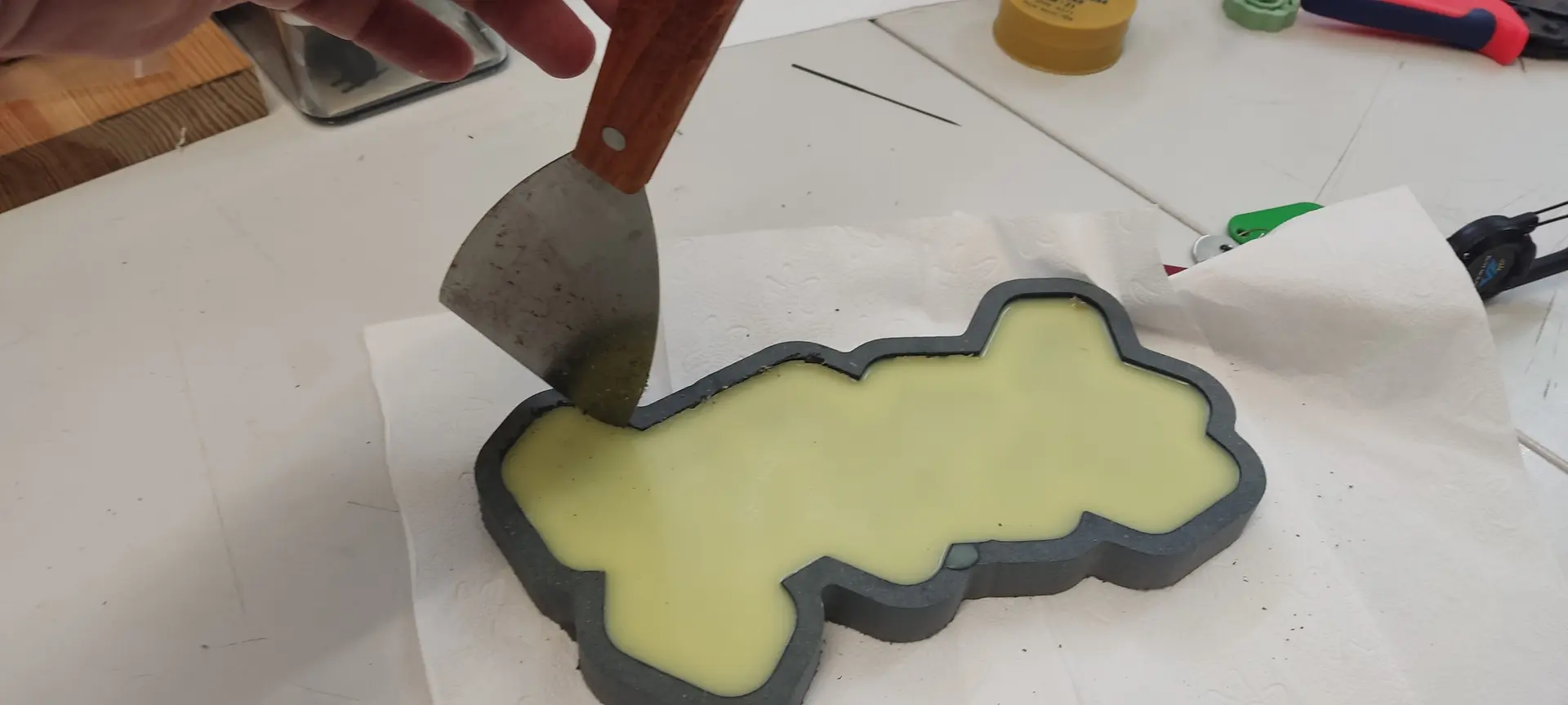
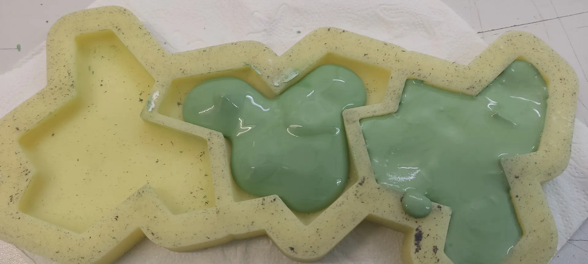
I pour the mixture, but because it’s still quite thick, it does not flow into all corners, so I have to manually push it a bit with a tool:
While I let this dry, I made another silicon mold, so we could produce more at a time.
Hero shot
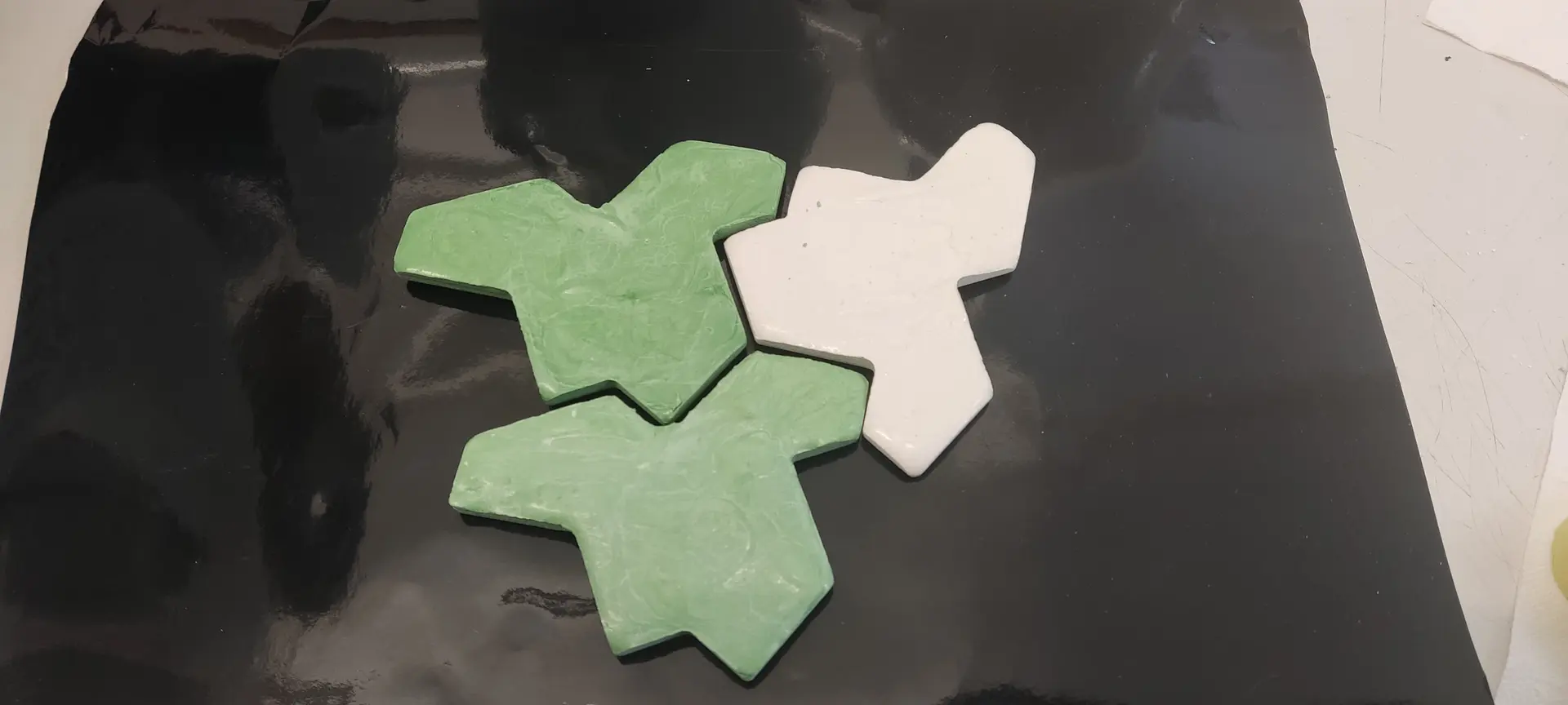
This is the result of the first batch:
And putting it together with the 2nd batch:
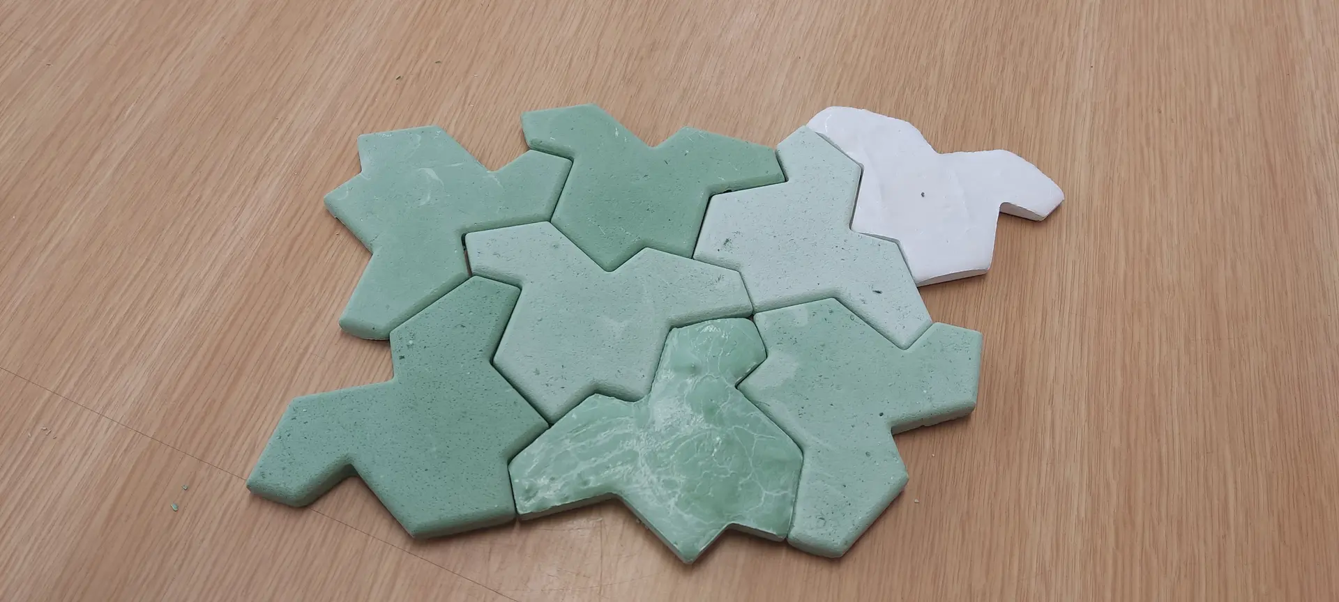
Notice, however, that only then did I notice that in order to fit all together, some shapes need to be flipped up, and that’s why the finish looks different. This means I should have made 2 opposite molds shapes, although geometrically the shape is the same.
Follow up
Given that André had changed the box container into something that is an offset of the shapes, he encouraged me to learn how to do the same.
So, after I completed this assignment, I tried to design it with the offset, rather than a square box.
FreeCAD offset ?
Sadly I ran into a lot of problems and quirks of FreeCAD.
One problem was that it was drawing an offset in the original place and size that the SVG imported to, and not the place and size I transformed it to.
Then, when I figured how to work around it I ran into other problems:
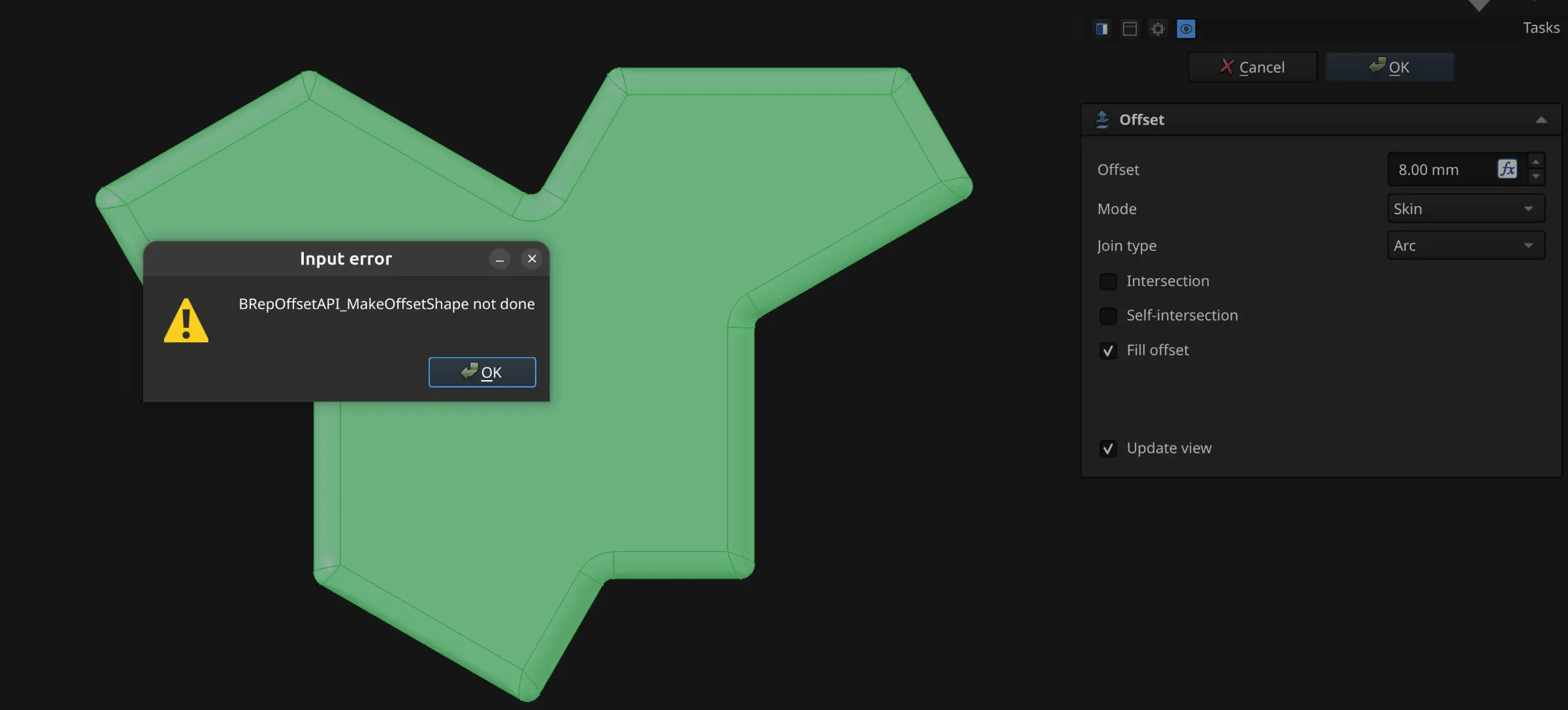
I investigated, and it seems this problem arises when the engine cannot compute the outline because the shape is too complex.
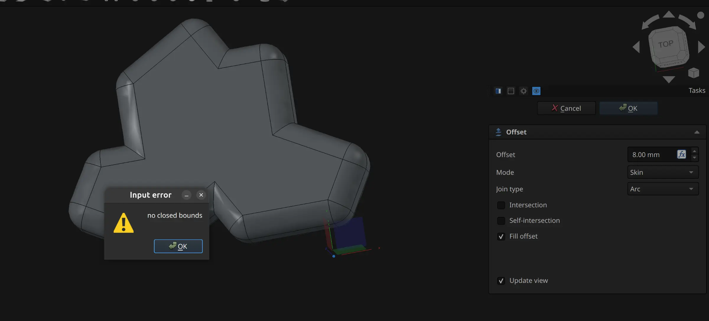
I suspected that the “complexity” was due to all the fillets that I had introduced, so I started from scratch and tried to compute the outline before applying the fillets.
Finally, I was able to see a somewhat correct preview of the offset, but when I clicked OK, I got another error:
After fighting a bit more with FreeCAD and going nowhere, I basically gave up on FreeCAD and decided I’d better invest time in trusty and more predictable OpenSCAD.
OpenSCAD
Rounding
OpenSCAD is pretty straightforward on importing SVG
I first needed to round the edges of the basic shape. The “trick” to accomplish this seems to be to apply an offset followed by an equal negative offset. This rounds the outside (convex) corners. If we apply it in the reverse order, than we round the inside (concave) corners. It thus follows that if we add the 4 operations and collapse the middle ones, we reach the desired effect:
module round_all(r) {
    // round outter corners
    offset(r=r)
    offset(r=-2*r)
    // round inner corners
    offset(r=r)
    children();
}
Extrude with draft
Such operation does not exist in plain OpenSCAD.
While the linear_extrude operation does support a scale parameter, I found it inadequate because it lead to uneven angles and underclines for this complex shape. In reality what we want to achieve is that the top of the shape looks like a negative offset of the bottom outline rather than a scaled down version of it.
This effect can be achieved by applying a minkowski sum between a flat shape and a cone of the desired extrusion height and and with the desired draft angle. Something like this:
module drafted_extrude(height, draft_angle) {
    // Calculate the total offset distance based on height and angle
    draft_offset = height * tan(draft_angle);

    // Minkowski sweeps the base shape with the cone profile.
    minkowski() {
        linear_extrude(0.001) {
                offset(delta=-draft_offset) children();
        }
        cylinder(r1=draft_offset, r2=0, h=height);
    }
}
If we flip the cone upside down, we have a “reverse” draft that we can use to subtract shapes.
I now have the basis needed to apply all operations needed.
Meta molds !
At this point, André suggested that we could make tiles with the actual technique used to produce traditional tiles (instead of using cement) and this is something I could do for wildcard week, but everything would need time to dry, so we needed to prepare in advance.
So this techinque requires that the mold for the tile needs to be done in plaster.
To make the plaster mold, we need to cast it in a silicon mold. And to make the silicon mold we need another hard mold ! 🤯
It required a bit of thinking and some sketches, but I finally came up with the needed shape.
This is what it what I came up with:
I exported this into an STL file, and then André taught me how to configure and use the Chitubox app for the resin printer to print this.
This is what we got:
Upon inspection though, I realized that the draft angles for the actual tiles weren’t exactly right.
I figured that the mistake was applying the extrude with draft to both tiles at the same time. While applying it to the offsets was fine to treat both shapes as a single one, for the final tile carving, I should have applied it individually, and thus would have to fix this and make another print.
I ended not doing it because meanwhile I got another idea for wildcard week 😅
There I also document a bit more the usage of the resin printer and its software.
Files
inset svg tile
freecad file
step file
Fusion file
Post processed nc file
OpenSCAD file