CAD explorations
Intro
I prefer FOSS (Free and Opens Source) solutions.
Also, as much as possible I’d like to run everything on Linux and not boot into Windows or having to run virtual machines with it, and avoid cloud solutions.
So, even though my instructor is most experienced with Fusion 360 and we are entitled to a 1 year student licence, I didn’t really want to invest time into a tool that I would most likely not be using after the course ends.
The main contenders matching the above requirements seem to be OpenSCAD and FreeCAD, so that’s what I explore here.
For the purpose of these exercise, I’ll try to model the main arch and standing blocks of my final project. I won’t strictly model the same dimensions, just the same features.
OpenSCAD
OpenSCAD feels quite familiar for a developer used to coding.
In OpenSCAD shapes are constructed by code that describes basic shapes, combines them and transforms them.
A useful resource is this Cheat Sheet which covers almost anything that you would need.
The Arch and slot
I need to design an arch, which is the main body of my final project.
Since there’s no primitive to design such a thing, one way that we can approach it, is to design a “tube” and then cut half of it.
A tube is just a cylinder where we remove the inner part of it:
h= 10;
or = 10;
ir = 5;

difference(){
    cylinder(h,or,or);
    cylinder(h,ir,ir);
}
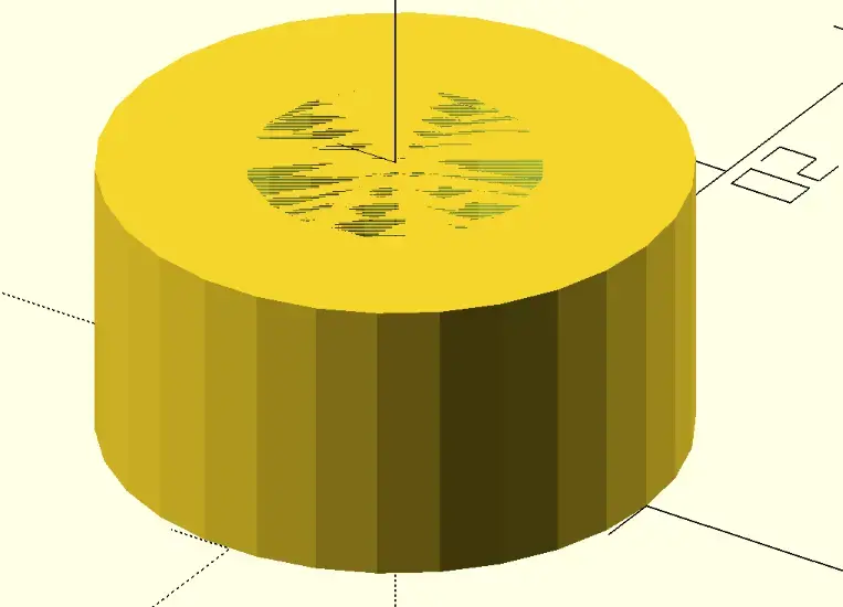
We can see what is called Z-fighting, because on the Z axis, we’re removing something that exactly matches the same plane, so the engine get’s confused if something should be removed or kept. As general rule, the thing being removed should extend slightly beyond the original shape.
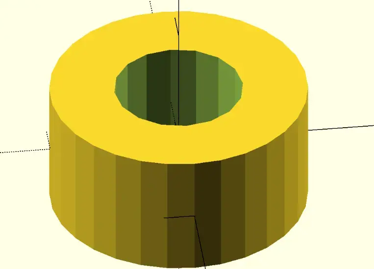
Let’s fix that.
difference(){
    cylinder(h,or,or,center = true);
    cylinder(h+2,ir,ir, center = true);
}
We make the height of the 2nd cylinder slightly bigger, and center both cylinders so that we don’t have to apply translations at this point.
One useful thing to see the operation being applied is that if we prefix the shape with # we can see the shape that is being subtracted:
difference(){
    cylinder(h,or,or,center = true);
    #cylinder(h+2,ir,ir, center = true);
}
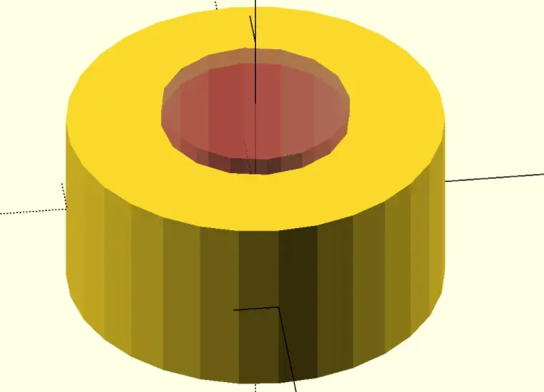
There are also other prefixes to make a shape transparent %, or the only one visible !, which help in debugging the process.
Having a tube shape seems like something we can use again, so I turn this into a module for reuse:
module tube(h,r,t) { //t for thickness
    difference(){
        cylinder(h,r+t,r+t,center = true);
        cylinder(h+2,r,r, center = true);
    }
}
I can now use this shape as if it was built-in. This one of the great things about code: reusability.
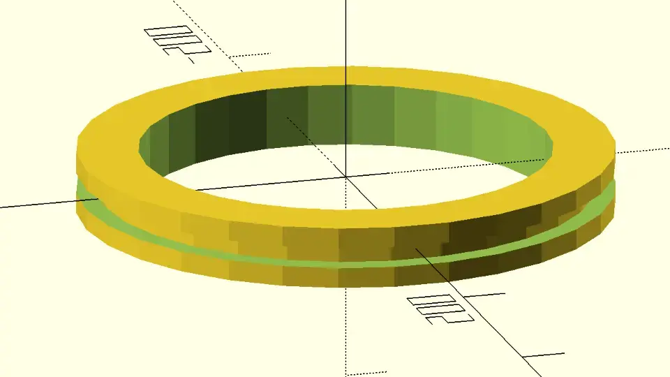
Now, before cutting out the half we don’t need, I want to have a slot on the outside of the arch, centered, so I subtract another tube in the middle and adjust a few sizes:
h= 30;
t = 30;
r = 100;

module tube(h,r,t) { //t for thickness
    difference(){
        cylinder(h,r+t,r+t,center = true);
        cylinder(h+2,r,r, center = true);
    }
}

difference(){
    tube(h,r,t);
    h2 = 10;
    t2 = 10;
    tube(h2,r+t-t2,t2+1);
}
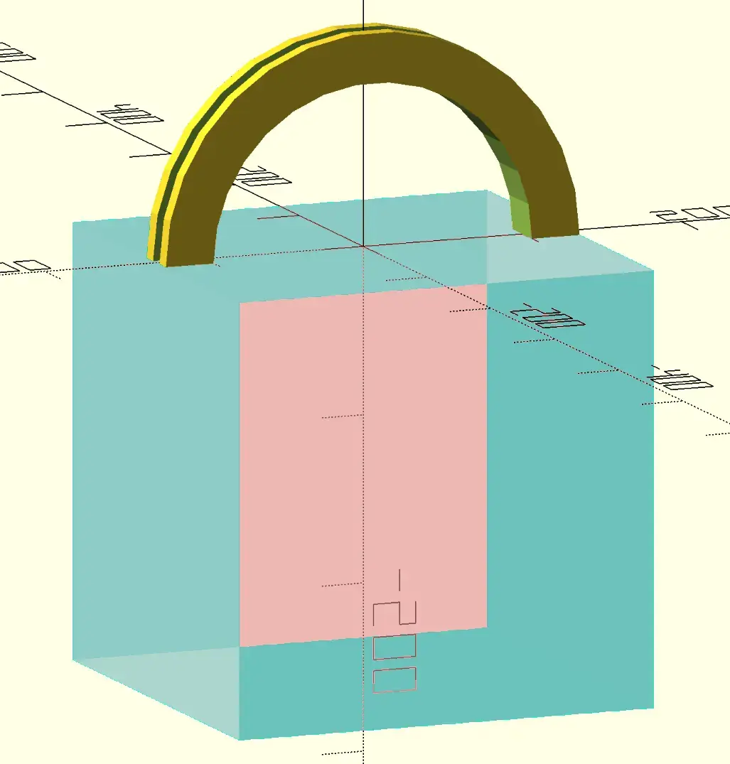
Looks good, so let’s rotate it upright and subtract a cube to cut the half we don’t need:
difference(){
    rotate([90,0,0])
        difference(){
            tube(h,r,t);
            h2 = 10;
            t2 = 10;
            tube(h2,r+t-t2,t2+1);
        }
    s=r+t;
    #translate([-s,-s,-2*s])
        cube(2*(r+t));
}
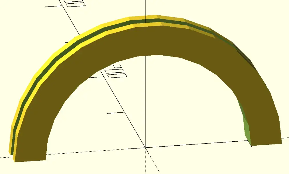
So we finally have our arch:
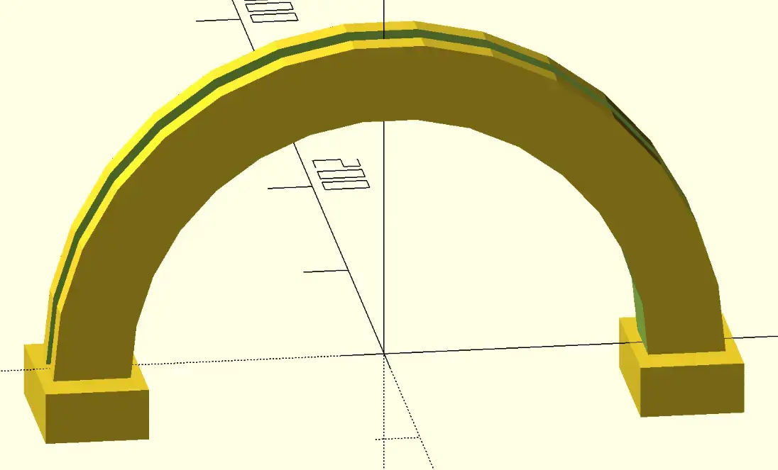
The supports
Now, to complete the main shape that I wanted, I’m missing some “boxes” that serve as the support on each side, so let’s add those:
bh=20; // box height
x = r+t/2;
translate([x,0,-bh/2])
    cube([40,60,bh],center=true);
translate([-x,0,-bh/2])
    cube([40,60,bh],center=true);
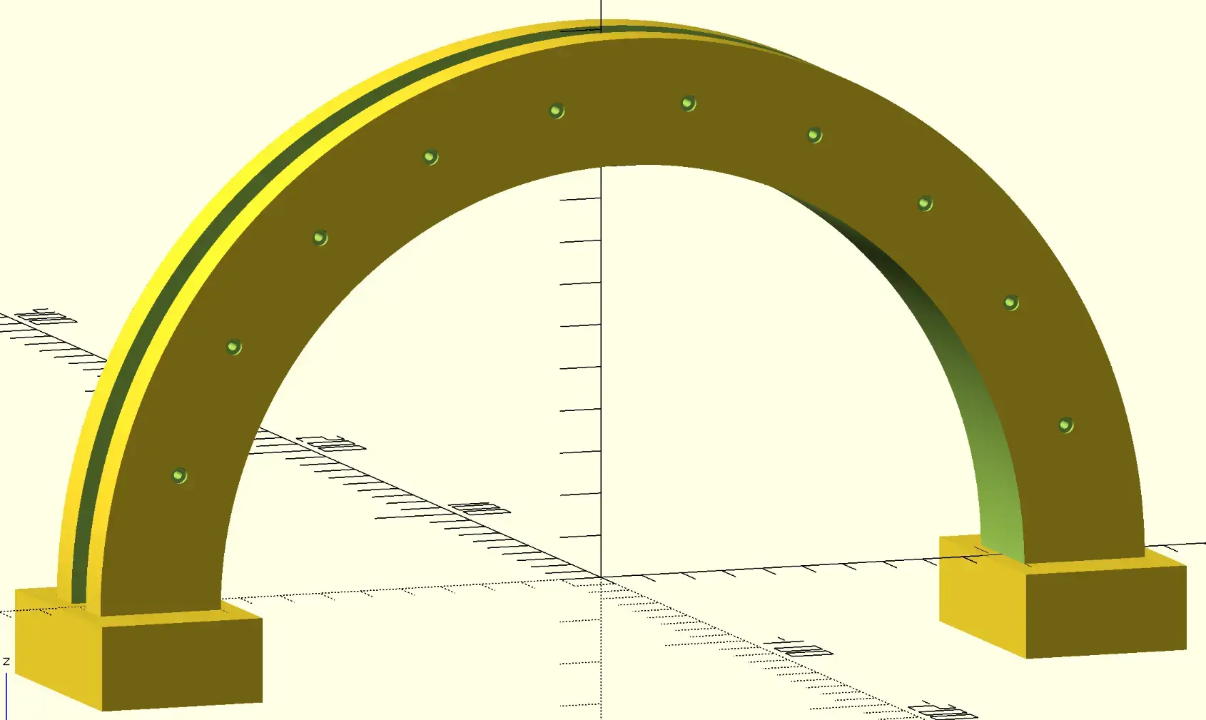
Nuts and bolts pockets
Finally, I’d like to have some openings for nuts and bolts, so I create the shape:
module boltnut(){
    br = 1; // bolt radius
    nh = 1; // nut height
    nr = 2; // nut radius
    cylinder(h+1,br,br,center = true);
    translate([0,0,h/2-nh+1])
        cylinder(nh+1,nr,nr,center = true);
    z = h/2-nh+1;
    translate([0,0,z])
        cylinder(nh+1,nr,nr,center = true);
    translate([0,0,-z])
        cylinder(nh+1,nr,nr,center = true);
}

and subtract it along the arch radius by using a loop and a rotation:
difference(){
    // main arch here
    x = r+t/2;
    num_bolts = 10;
    for (i = [1 : num_bolts ]) {
        rotate([90,i*180/(num_bolts+1),0])
        translate([-x,0,0])
        boltnut();
    }
}
And I get the result I wanted. Before the final render, I increase the the $fn internal variable to 360 to have finer curves. Since OpenSCAD is mesh based, it means curves are actually approximated to small segments. Setting this variable to a higher number makes curves look smoother, but also more computationally expensive.
FreeCAD
In the FOSS world, FreeCAD seems to be the prime contender. It has lots of workbenches with plenty tools including for CAM (Computer Aided Manufacturing), and it even has a OpenSCAD workbench.
To test this out, I opened the OpenSCAD workbench, and imported the previous design, and it was able to render it, even though if froze for a few minutes 😅
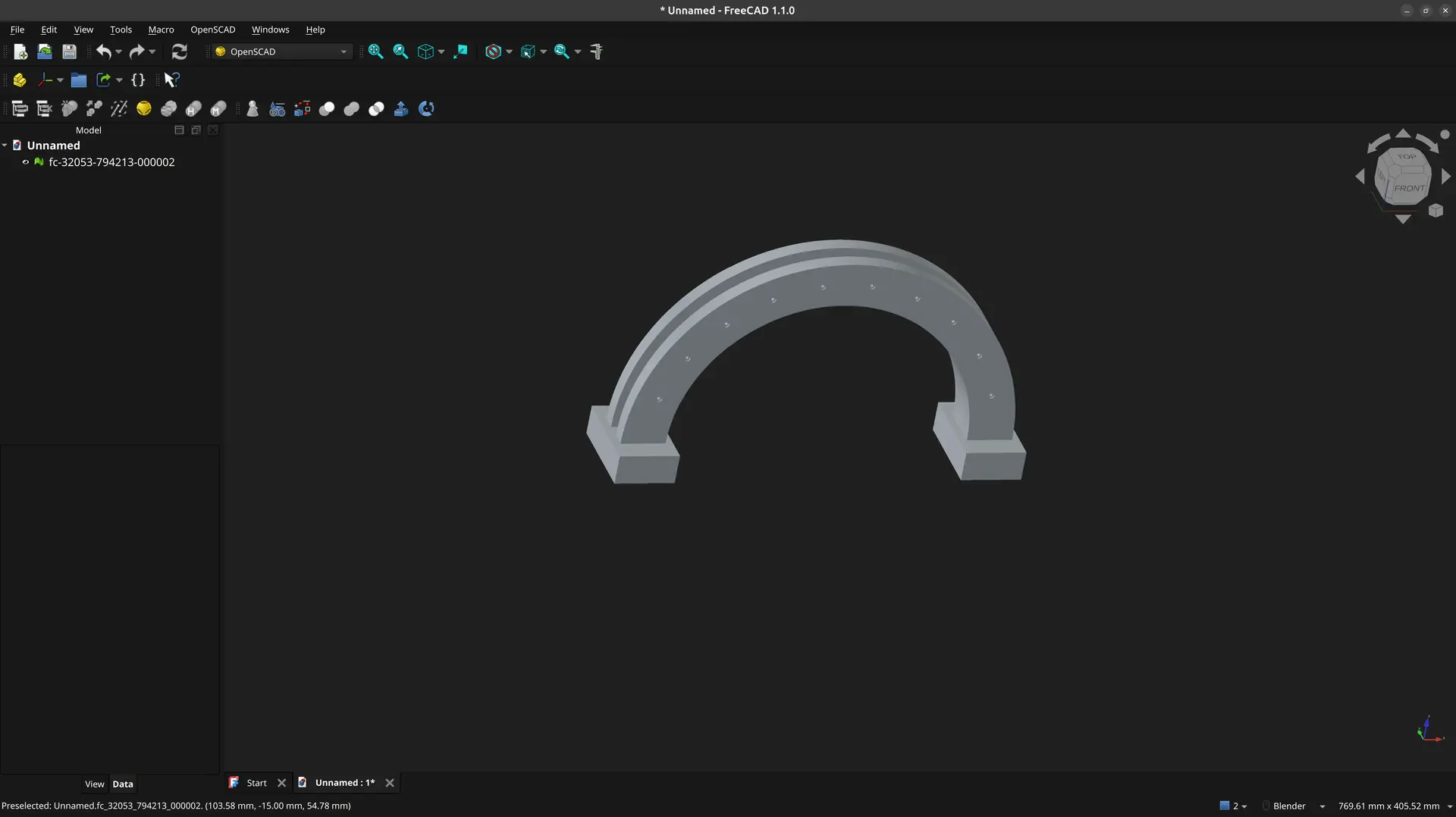
The way the design is usually approached though, is different. Instead of thinking about solids, the recommended way is to think in 2D and then extrude or carve those shapes into other solids.
So, let’s try to do the design in the recommended approach.
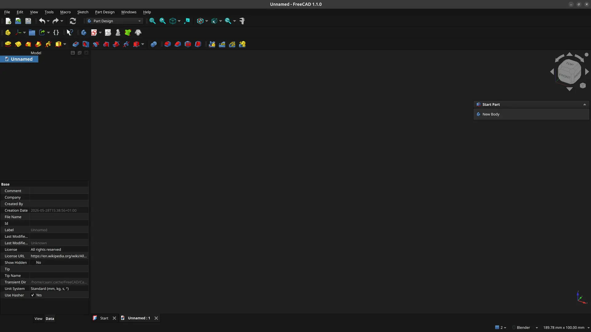
The arch
I start with an empty file, pick the Part Design workbench and click New Body under the Start Part tab
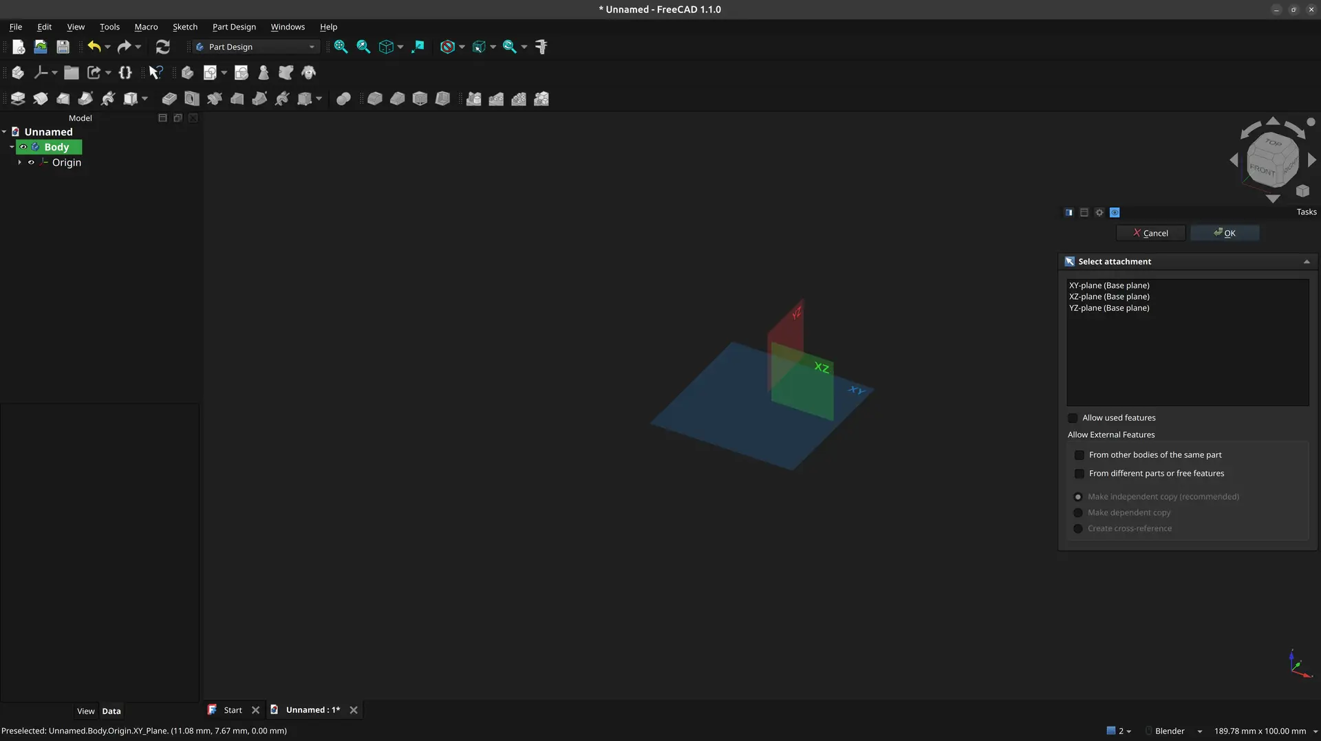
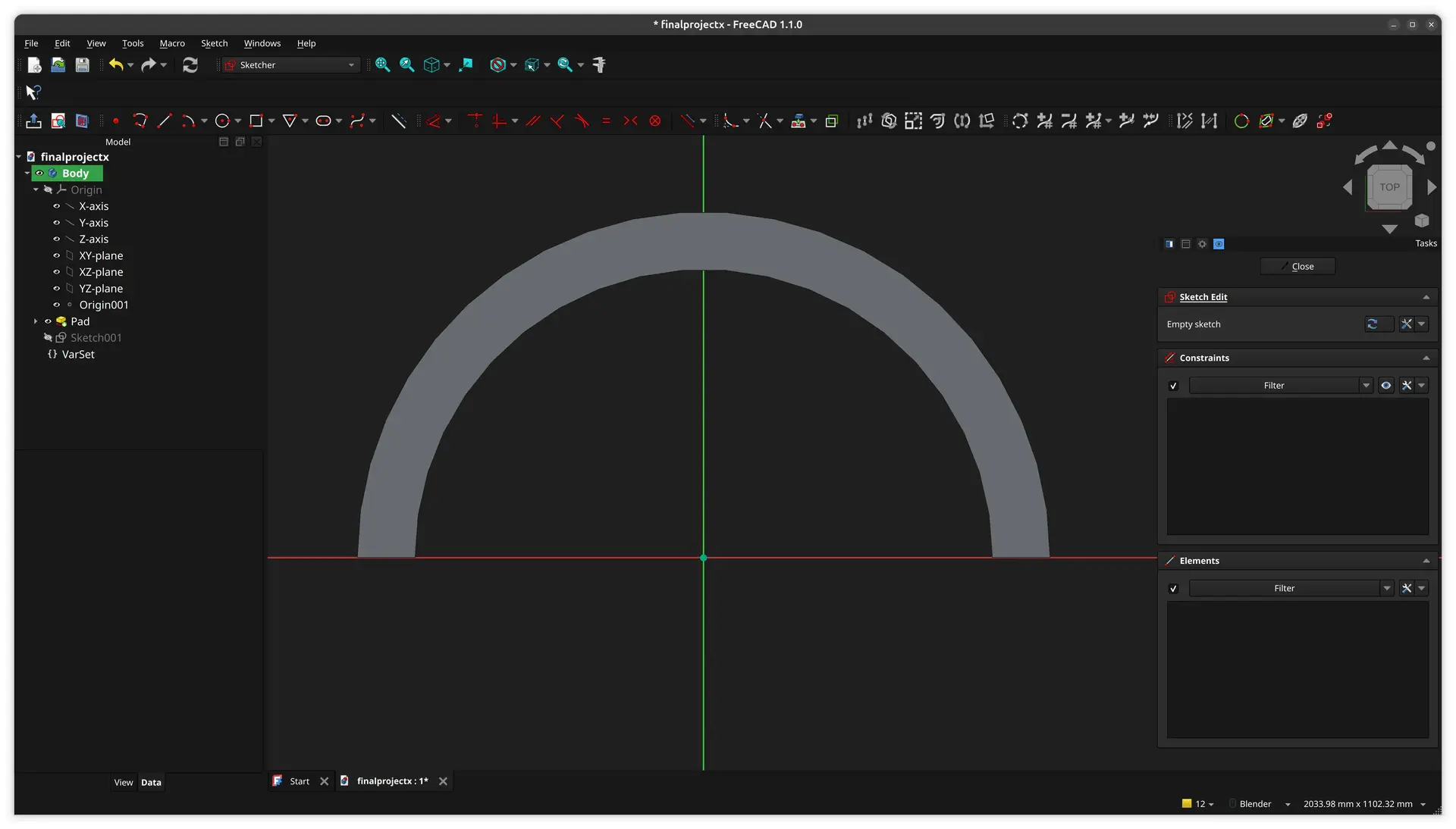
I then click New Sketch and pick the XY plane to start drawing
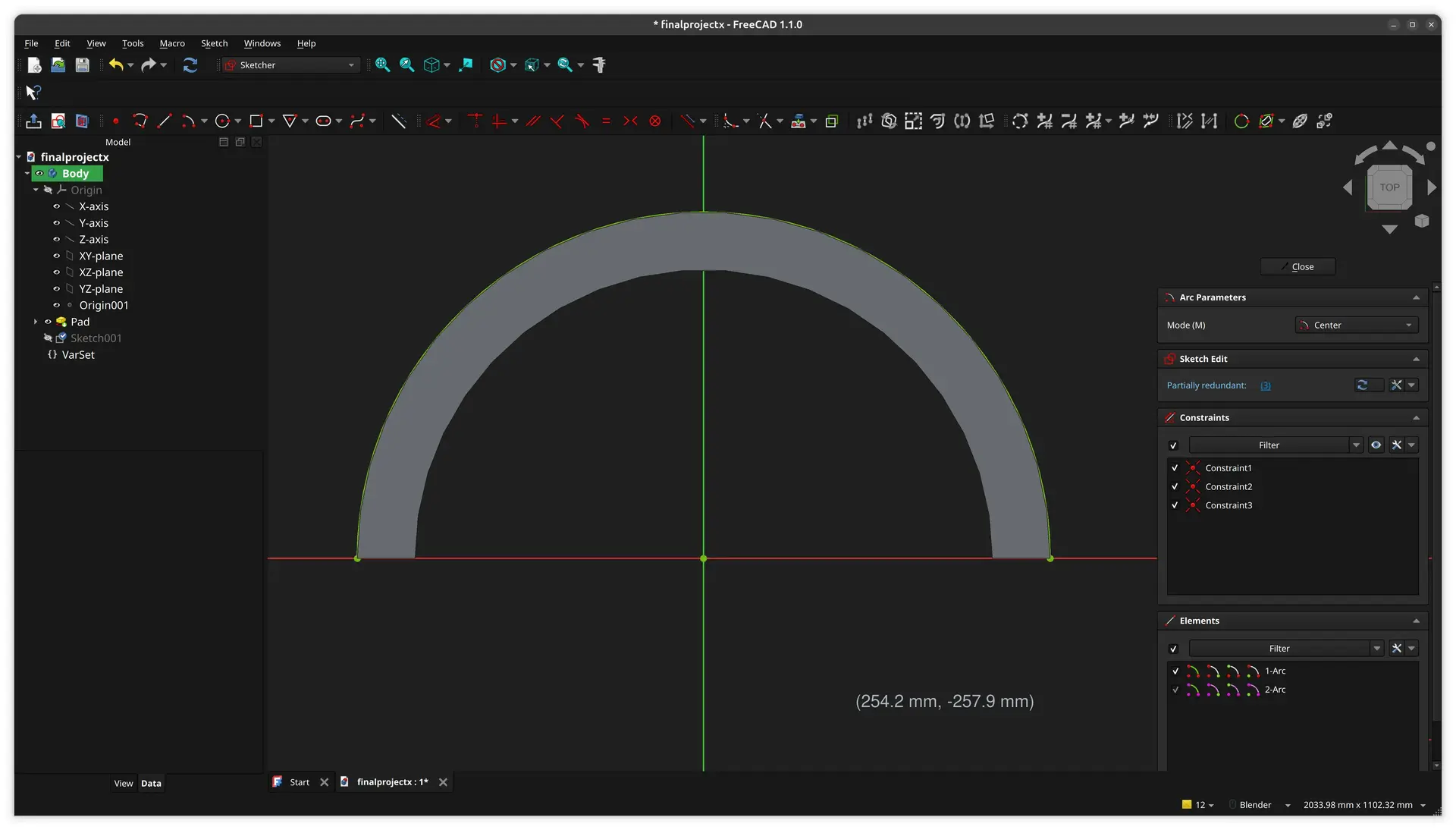
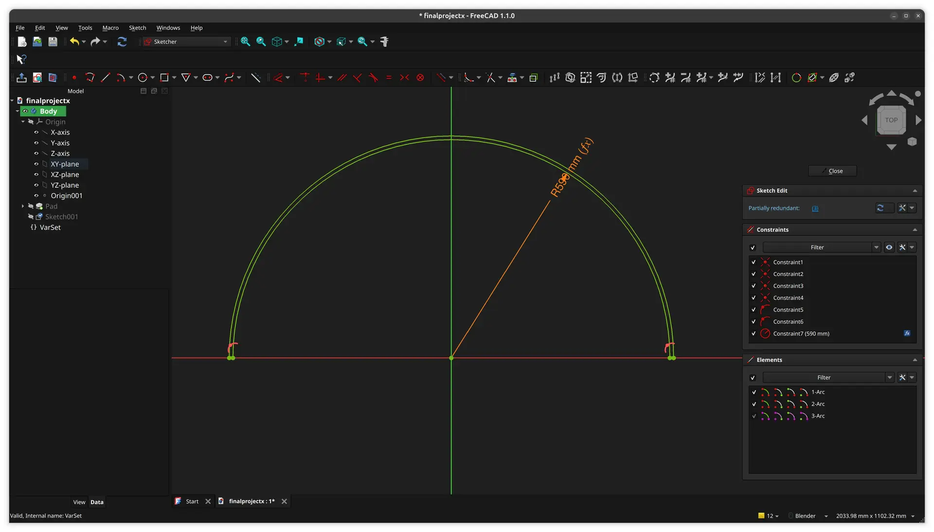
I pick the tool Arc from Center
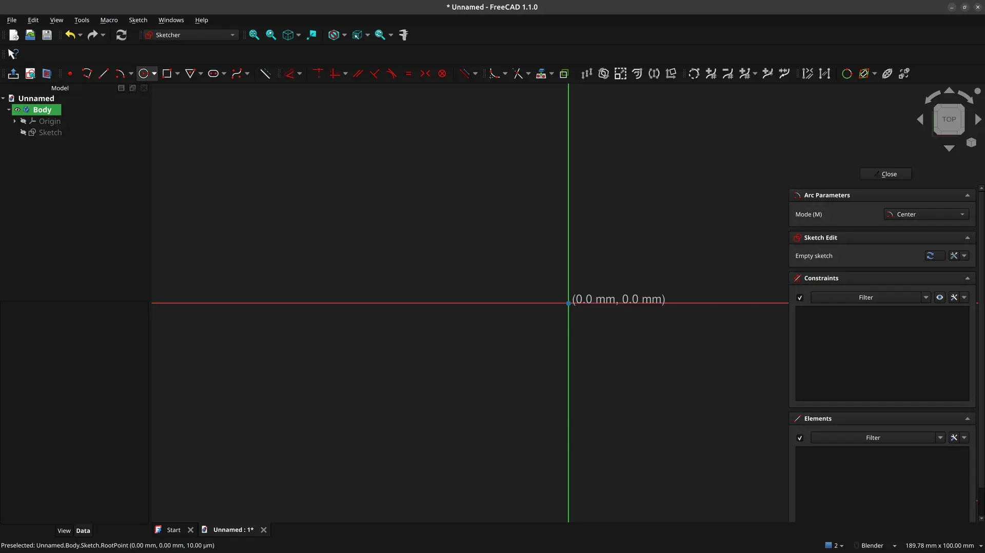
I have to click precisely the center of the sketch (the cursor changes when it’s at the exact spot), then type the dimension, click on one side of the plane, then the other. These also have to be very precise (again, the mouse cursor changes when it’s at the right spot). By doing so, FreeCAD assumes some default constraints, and the image should look like this:
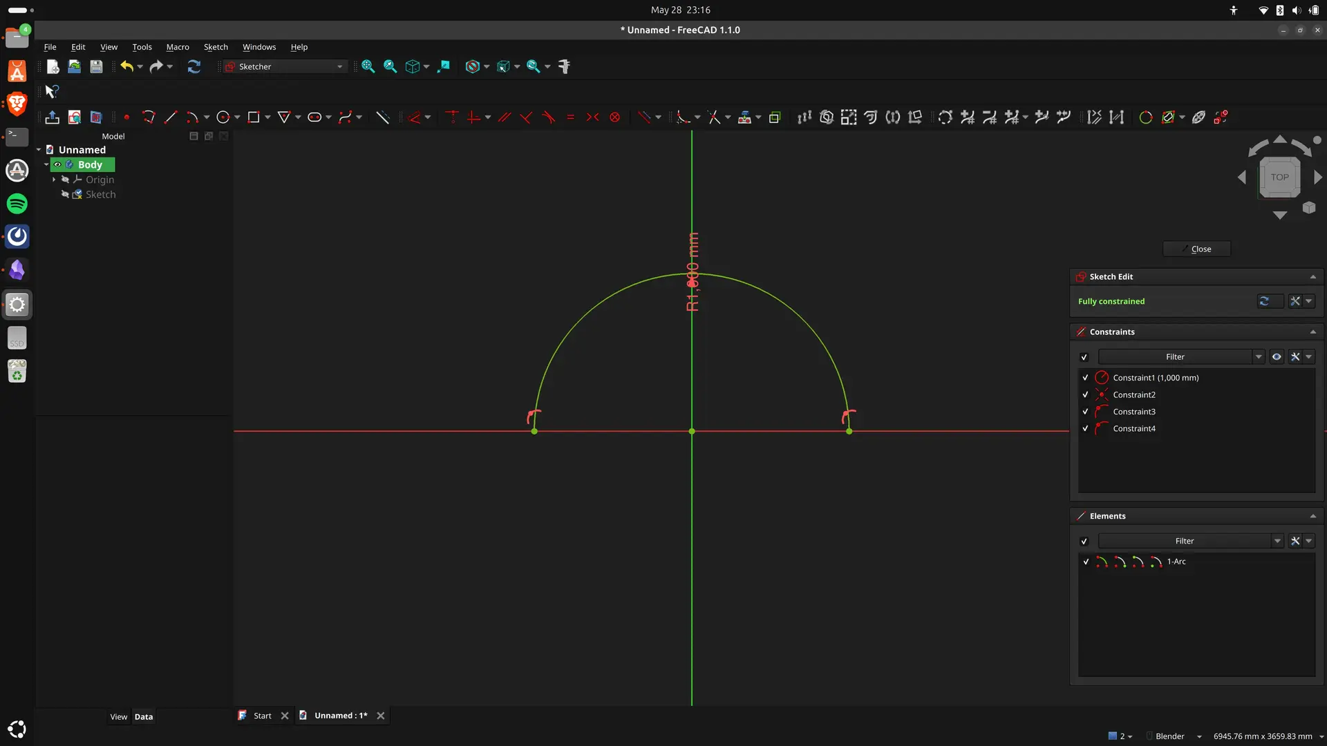
It shows as green, indicating that the sketch is fully constrained. Failing to be precise, implies that one must go afterwards and select points and lines and apply constraints manually.
Unlike OpenSCAD, where basically you just tell the coordinates and sizes where everything is, FreeCAD operates one the notion of defining relationships between lines and curves.
So you replace absolutes with sometimes an annoyingly high number of constraints and relationships. On the other hand, you avoid doing math to make things be in the right places. I’m not sure this is a trade I like 🤷♂
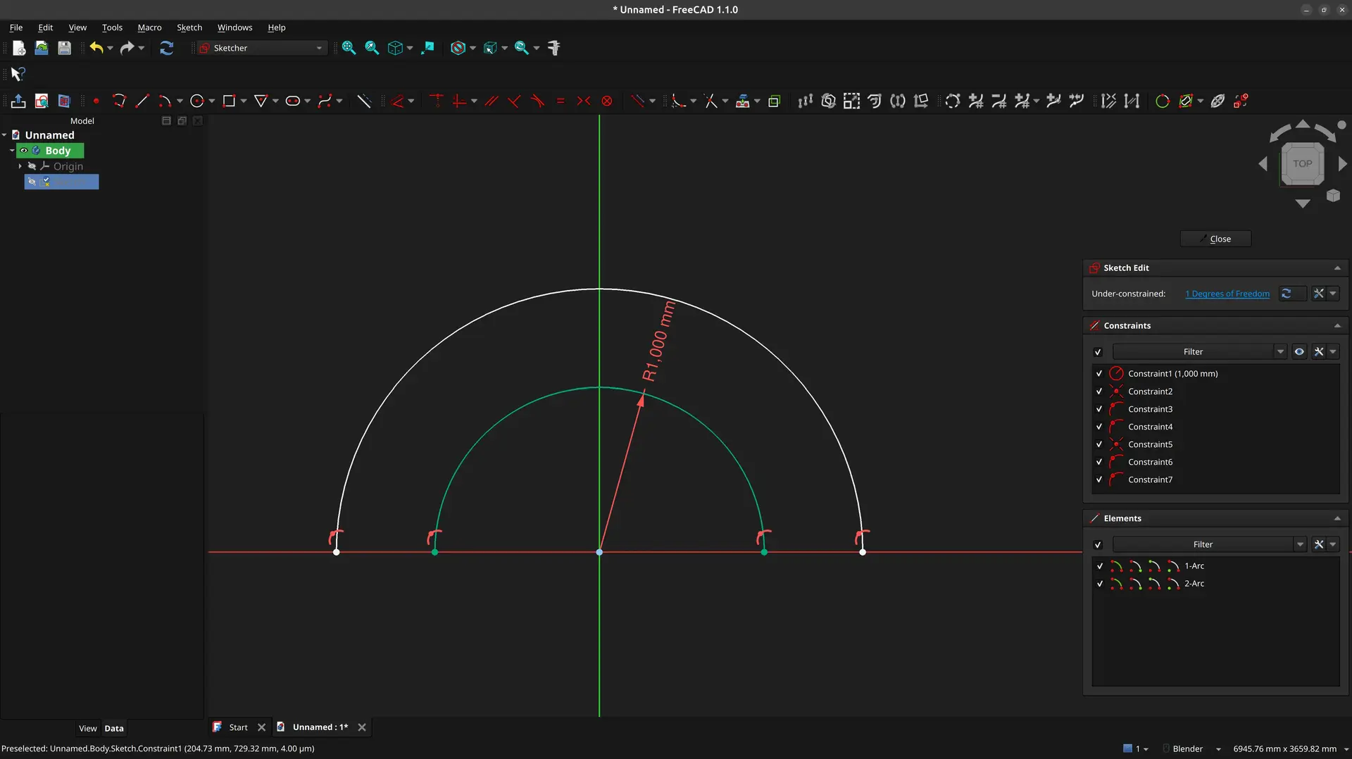
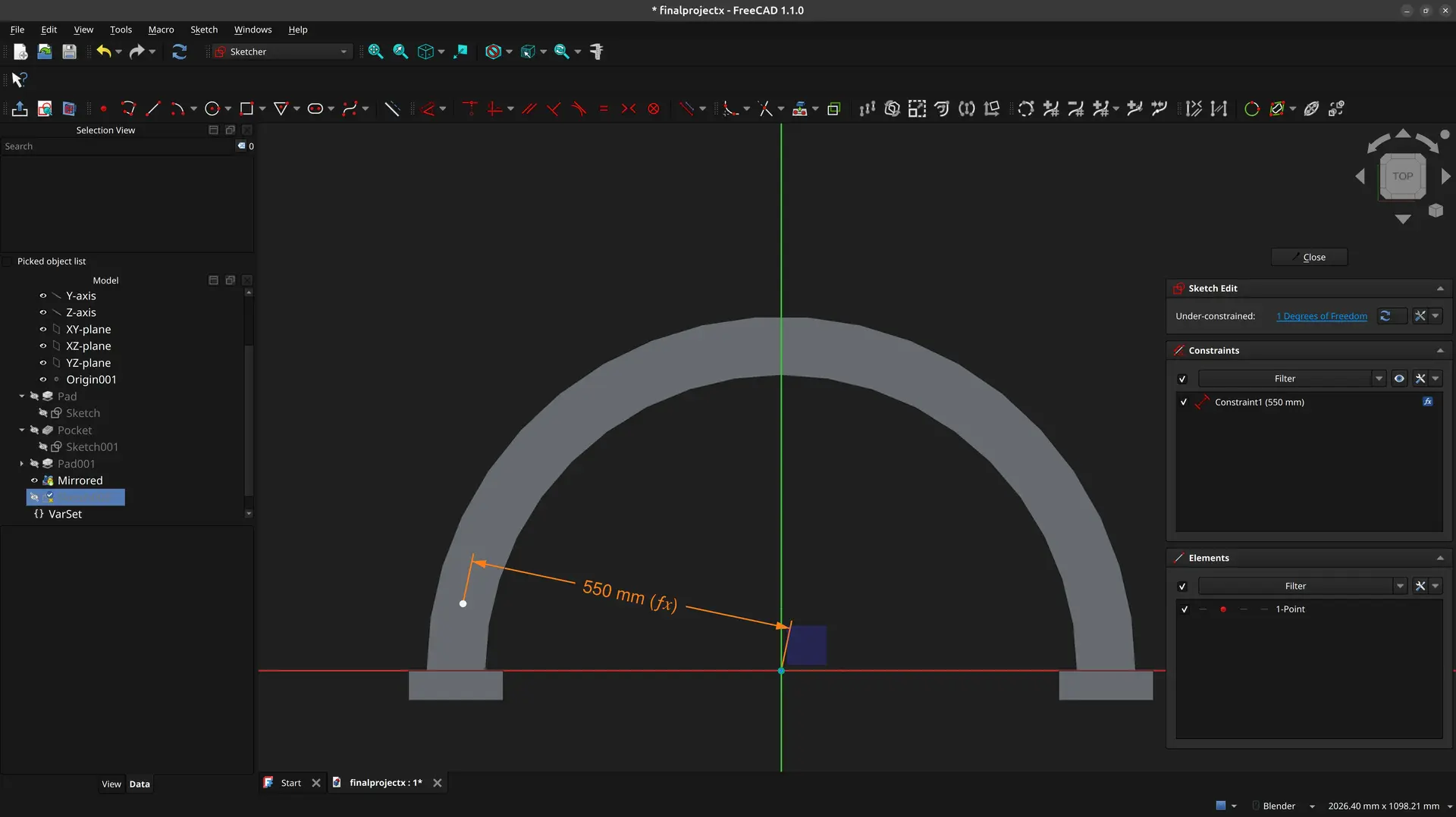
So I draw another arc, but this time I forget to type in the size. We can see that the sketch shows that it’s “under constrained”. If we click and drag the second arc, we can see that it moves.
Before we fix that, though, it’s time to make this parametric. Being parametric usually means that we can easily change some dimension numbers somewhere, and the whole design changes accordingly.
There’s a couple of ways of doing it. One way is to use the Spreadsheet workbench, and the other, more recent, is to use VarSet’s. I’ll show the later as I find it more straight forward.
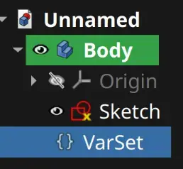
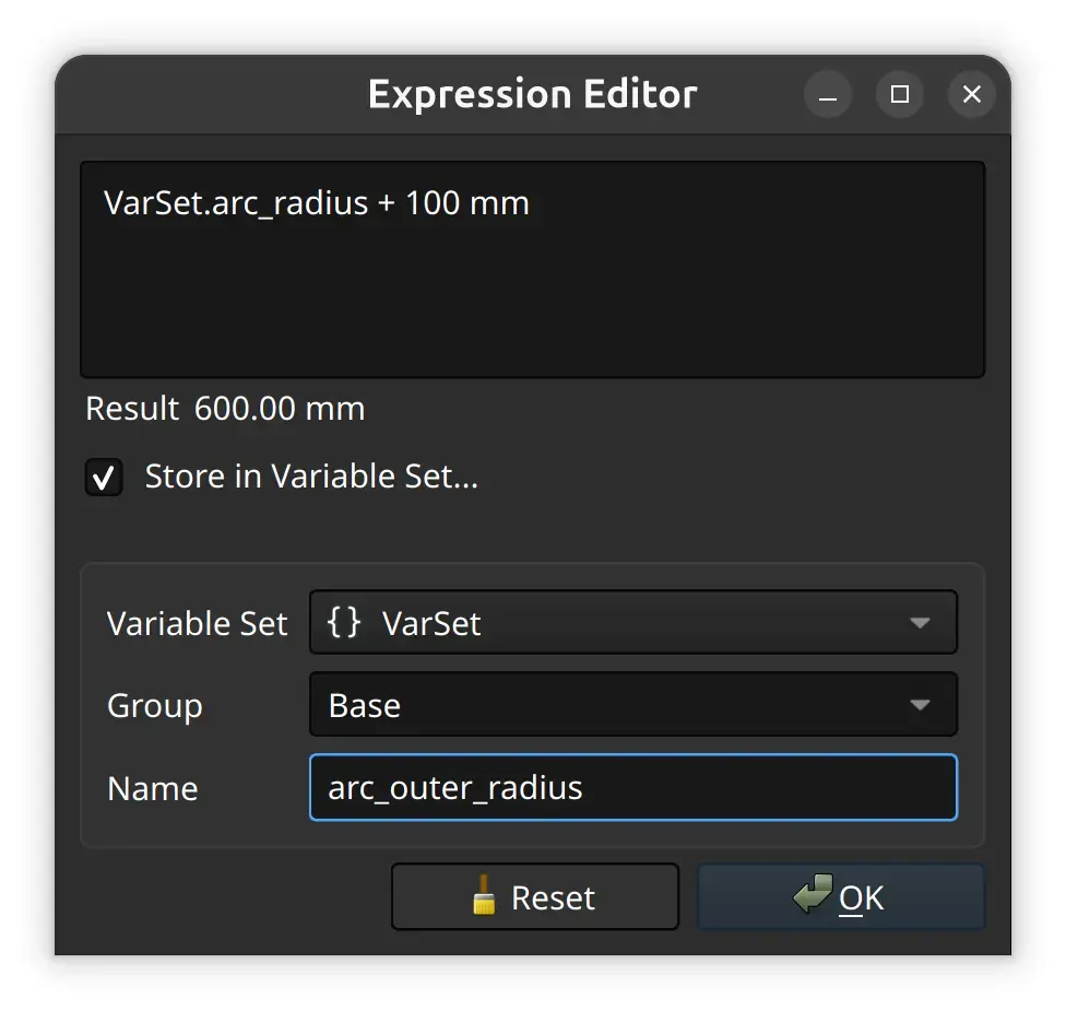
I first need to close the sketch 🤷♂ and click this icon:

A popup shows to add a variable, but we can close it.
We see in the object tree that a new VarSet item appears:
I double click the sketch again, and I’m back to editing it.
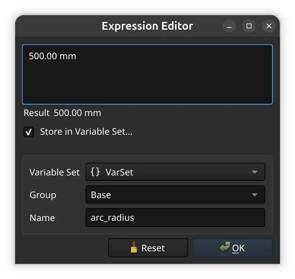
So, instead of setting the arc radius at 1000 mm, let’s turn it into a variable. I right click on the dimension in red, and click Edit value
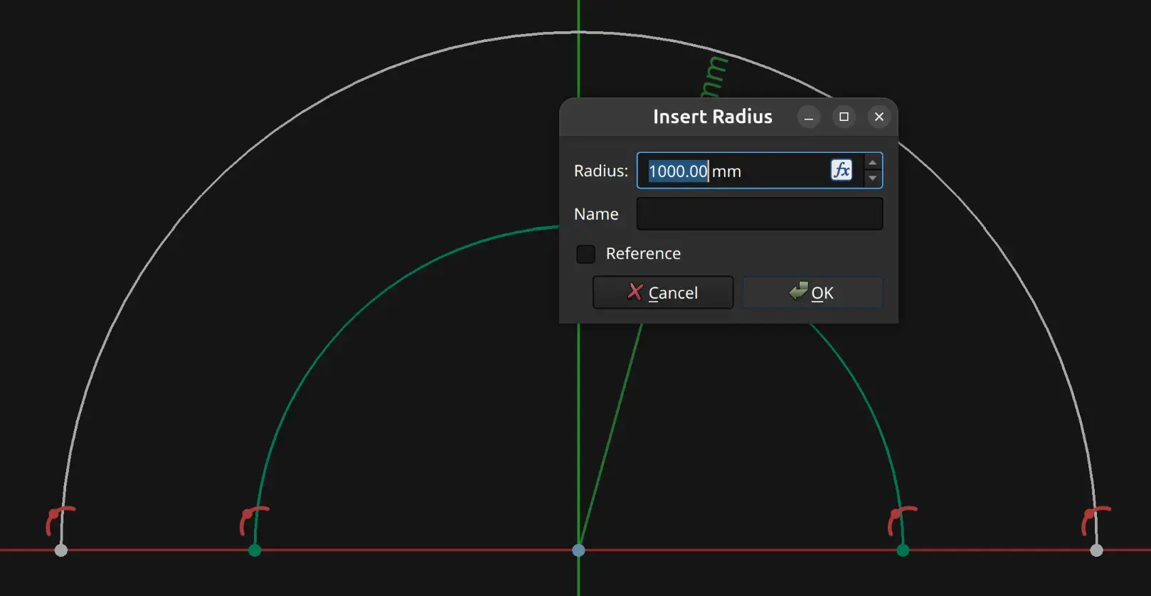
We see that next to the edit box, there’s a fx button. I click it , set a new value, enable the Store in Variable Set checkbox and name it arc_radius and click OK
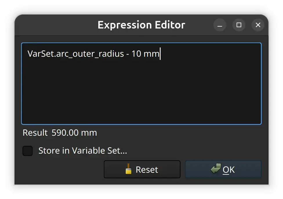
I then click on the outer arc, an then click the dimension tool:
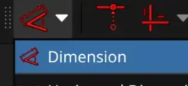
And click on the fx button again and fill this in.
Notice How I can now reference another named variable, and how it shows the current computed value.
Sadly, you’d expect this to work, but it doesn’t. It get’s confused and leaves it at 0 mm, and no property is added 🤦
So instead, I close the sketch again 🤷♂, double click the VarSet again, fill the values and click the fx button:
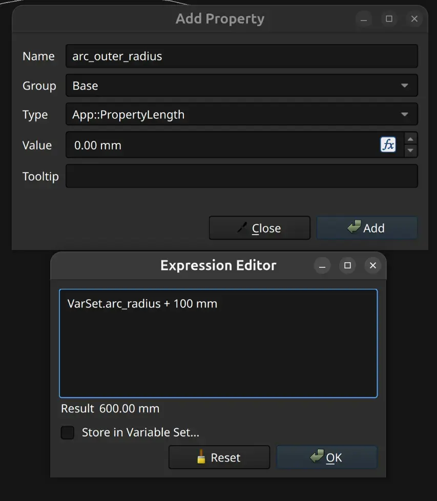
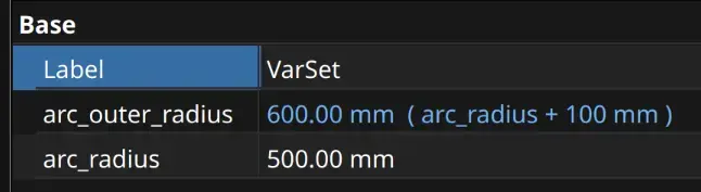
We can now see the 2 variables correctly defined:
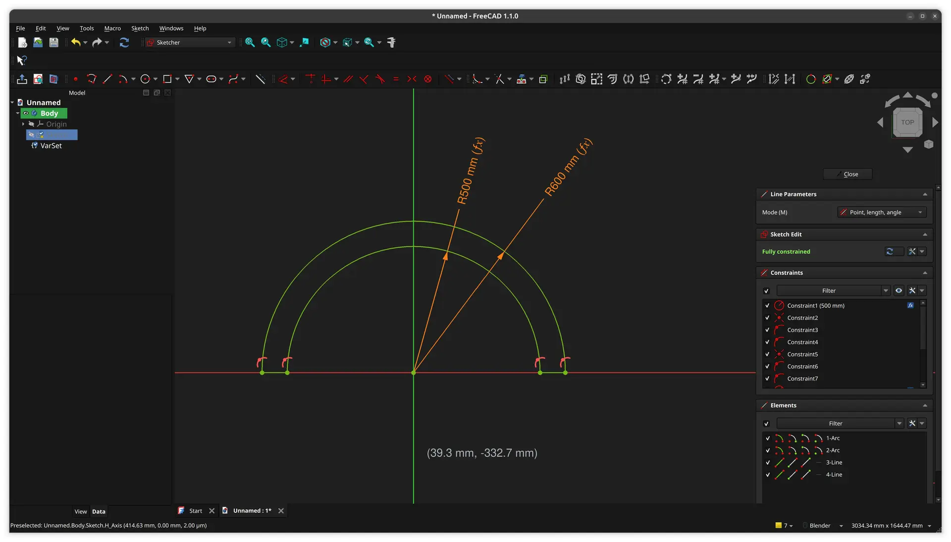
So, I now go back to editing the sketch, repeat the process of adding the dimension to the second arc, but this time I just type in the newly created variable name after I press the fx button, and now it correctly takes the new dimension.
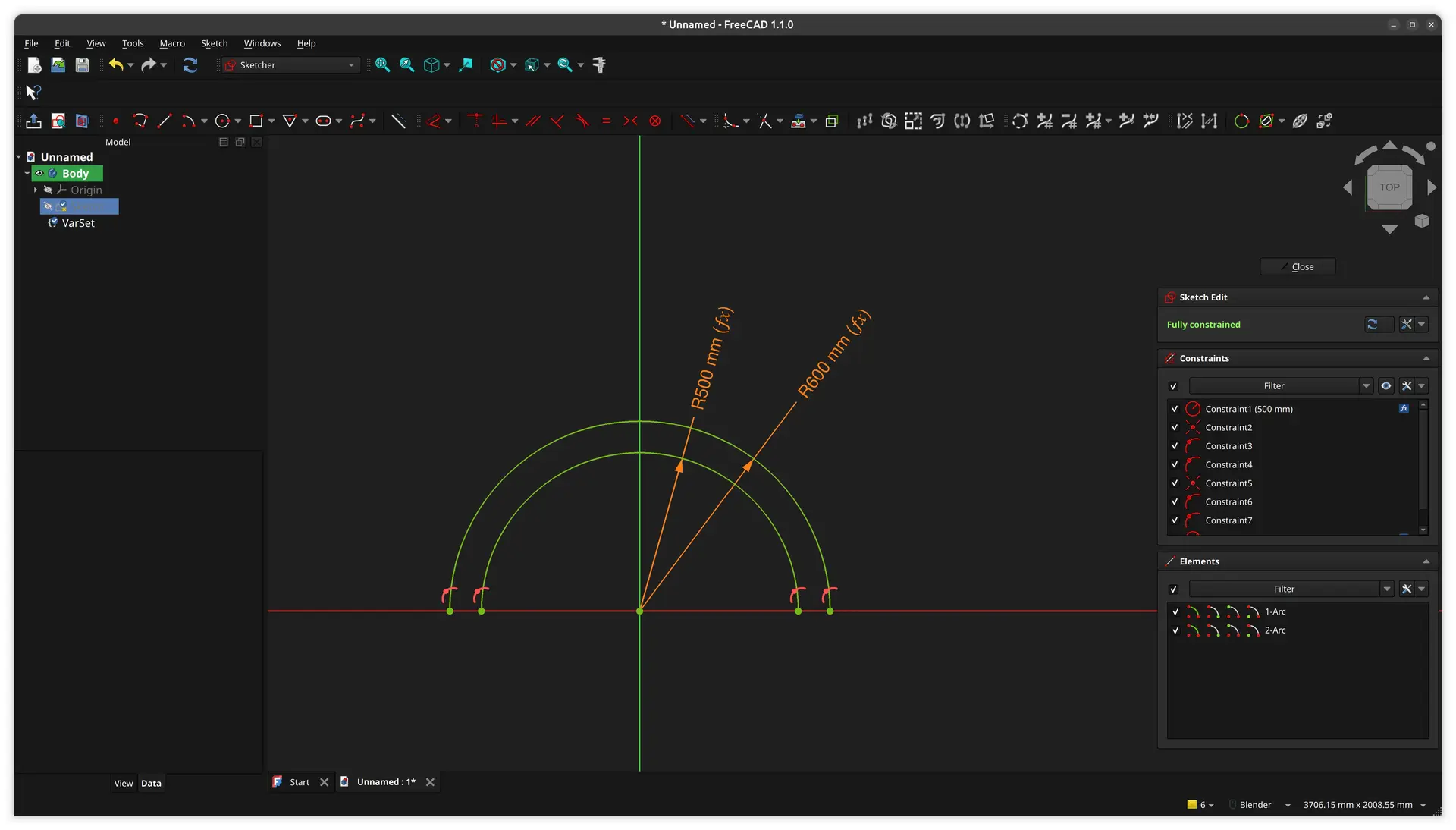
Everything is now fully constrained, but in order to extrude this into a solid, the shape must be closed, so I use the line tool to join both arcs.

Again, one must be very precise and only click the dots if it’s precisely over each vertex, at which point the mouse overlay changes and shows that the coincident constraint is being applied. Otherwise, it looks like it’s in the right place, but if you zoom a lot, you can see they’re not in the same spot. Then you would have to select both points and click the coincident constraint.

Hopefully if you have the fine motor skills of a clock worker or a surgeon, you can avoid the extra hassle by clicking the millimeter precision spots 🤷♂
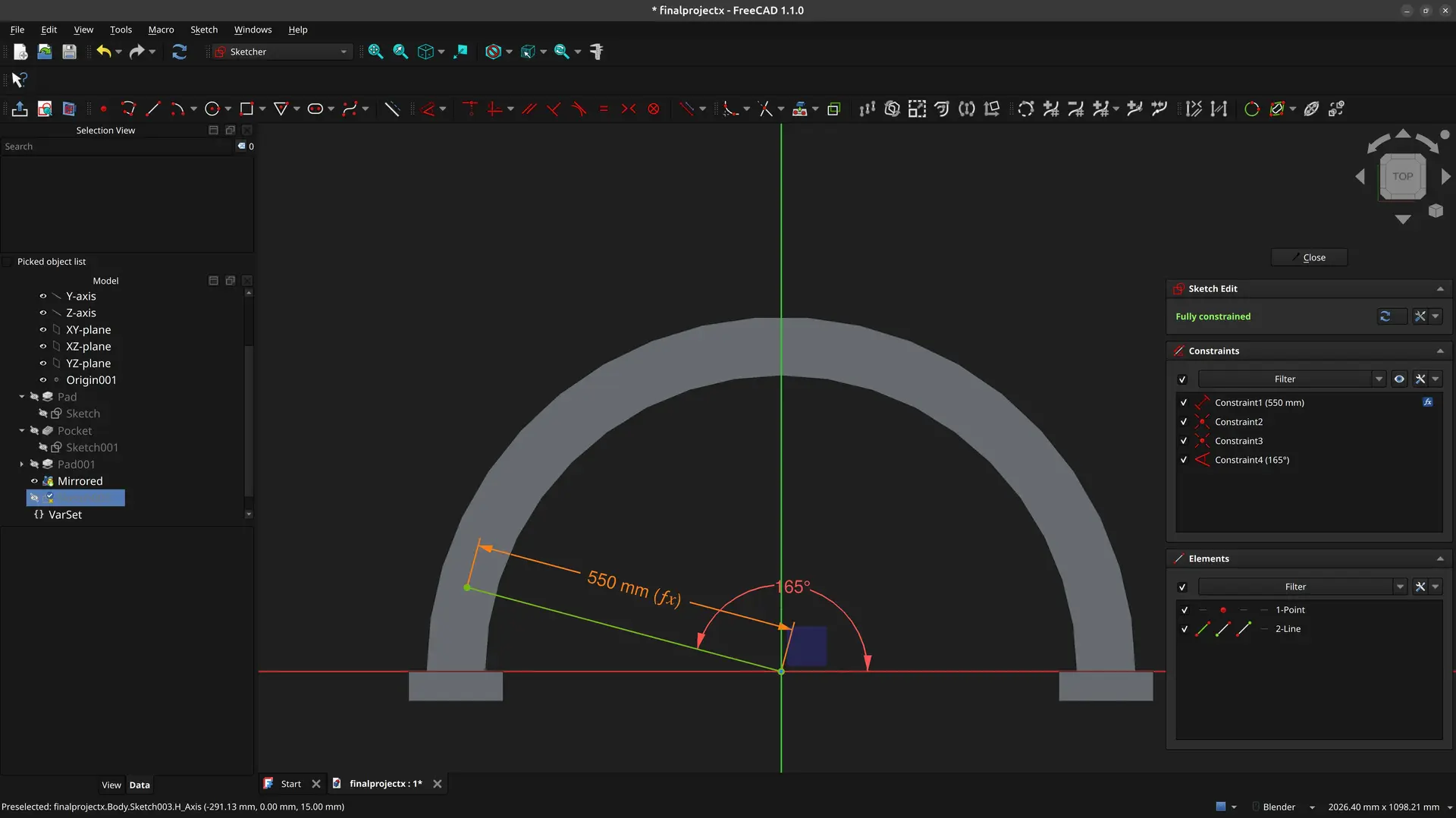
We now have everything green (fully constrained) and closed:
We are now ready do make this into a solid and extrude it.
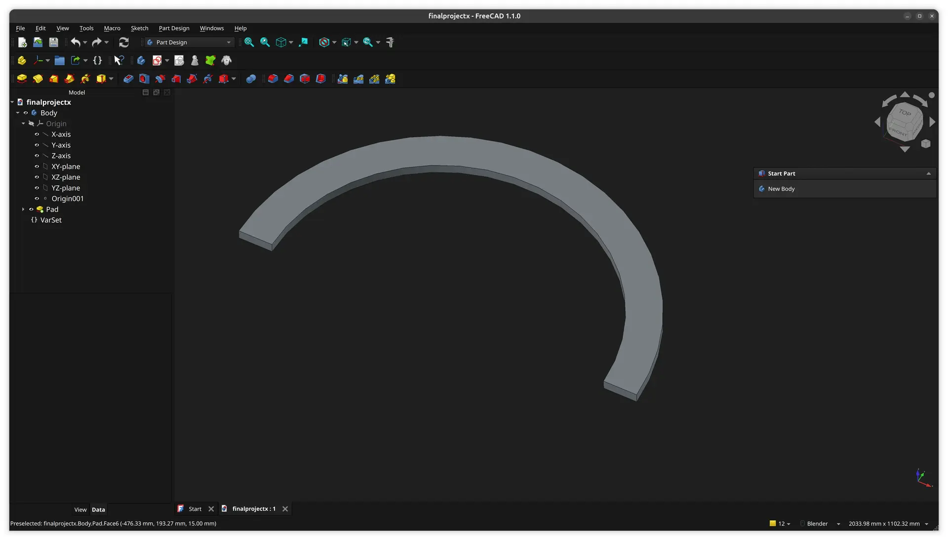
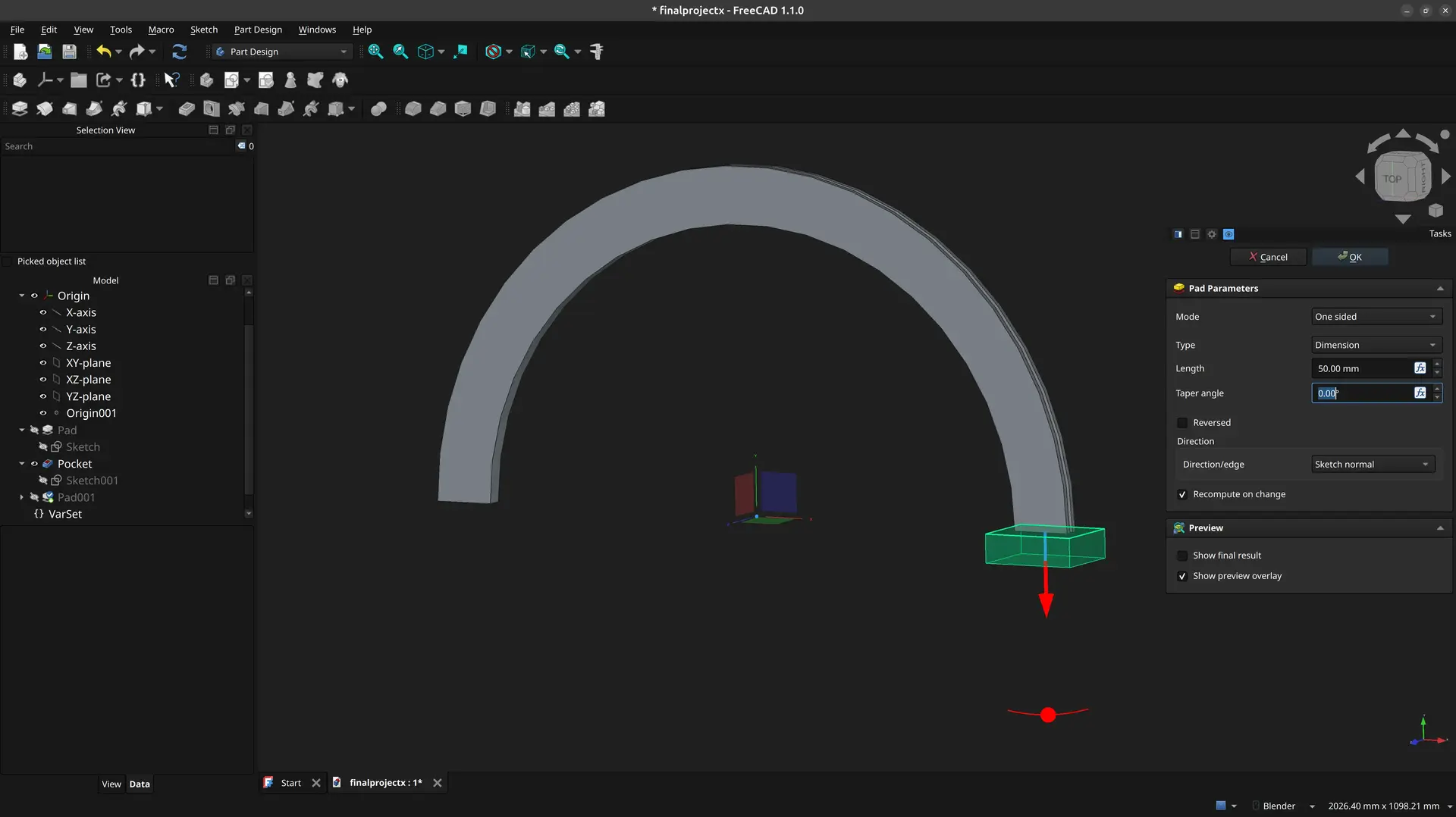
I close the sketch and pick the Pad option.
I choose the Symmetric option and also add the dimension to the VarSet.
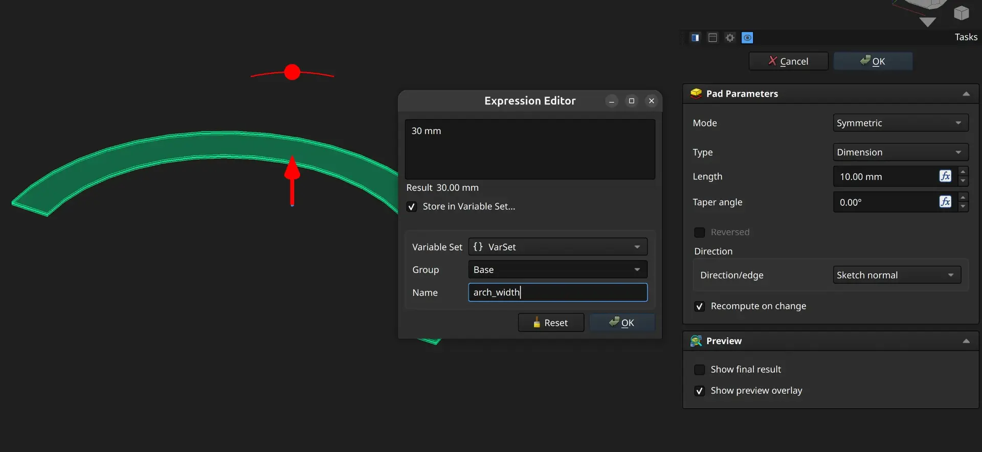
We get this:
The Slot
So, now I’ll cut the slot in the outer edge of the arch.
Because I made the padding symmetric, now just have to draw a smaller arch in the XY plane and apply the reverse operation, which is a Pocket
So, I don’t select any surface, but rather select the XY plane to start another sketch.
The outer part of the arch, should match the existing arch, so we have to “pull” that reference into the current sketch with the external geometry tool:

The arch turns purple, and we can now draw an arch over it similar to before. I click the center, then precisely both end vertices of the arch. I don’t have to specify the radius, because it matches the previous arch.
Now I draw a smaller arch by clicking center and then somewhere along the horizontal line.
I then click the dimension tool and then the arc, and click the fx button to add an expression.
The new arch get’s partially hidden by the existing solid, but if we press the visibility icon on the existing shape:

We can see it:
Now we just just join both arches with the line tool as before, and we can close the sketch.
We now apply the Pocket operation and make it symmetric as before
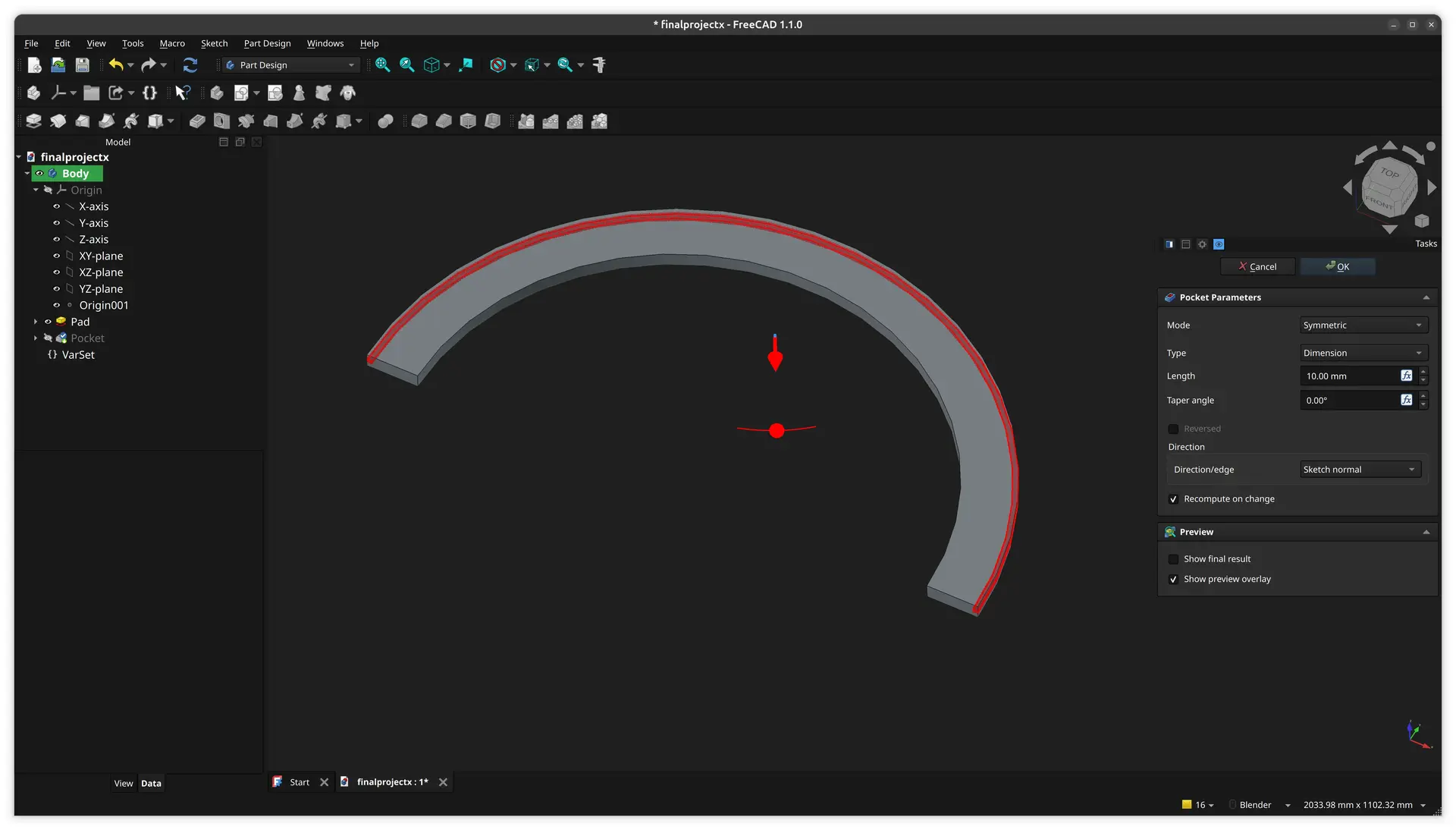
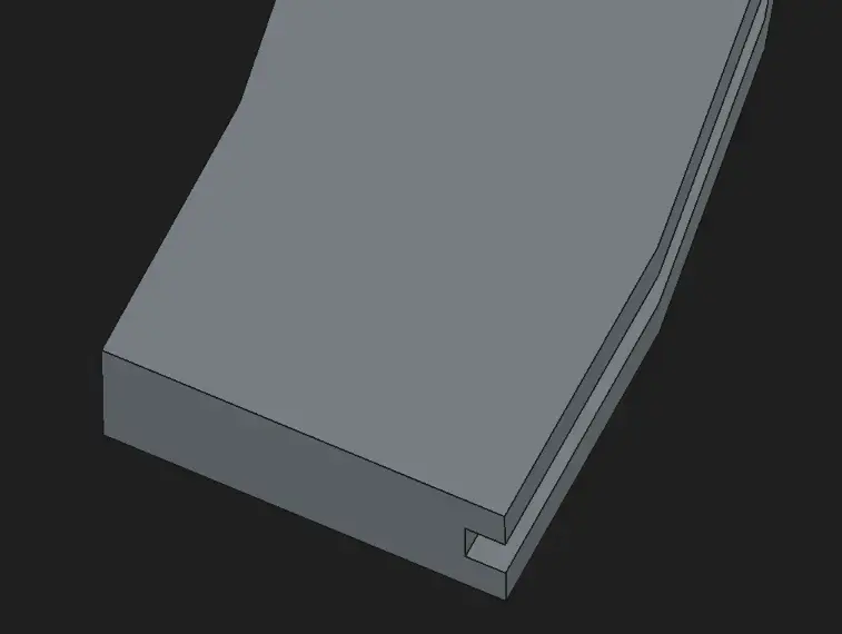
We can see that we now have slot all along the outer edge:
The Supports
I select the XY Plane again, and pull one of the edges as external geometry:
And draw a rectangle around it ithout bothering to set the dimension:
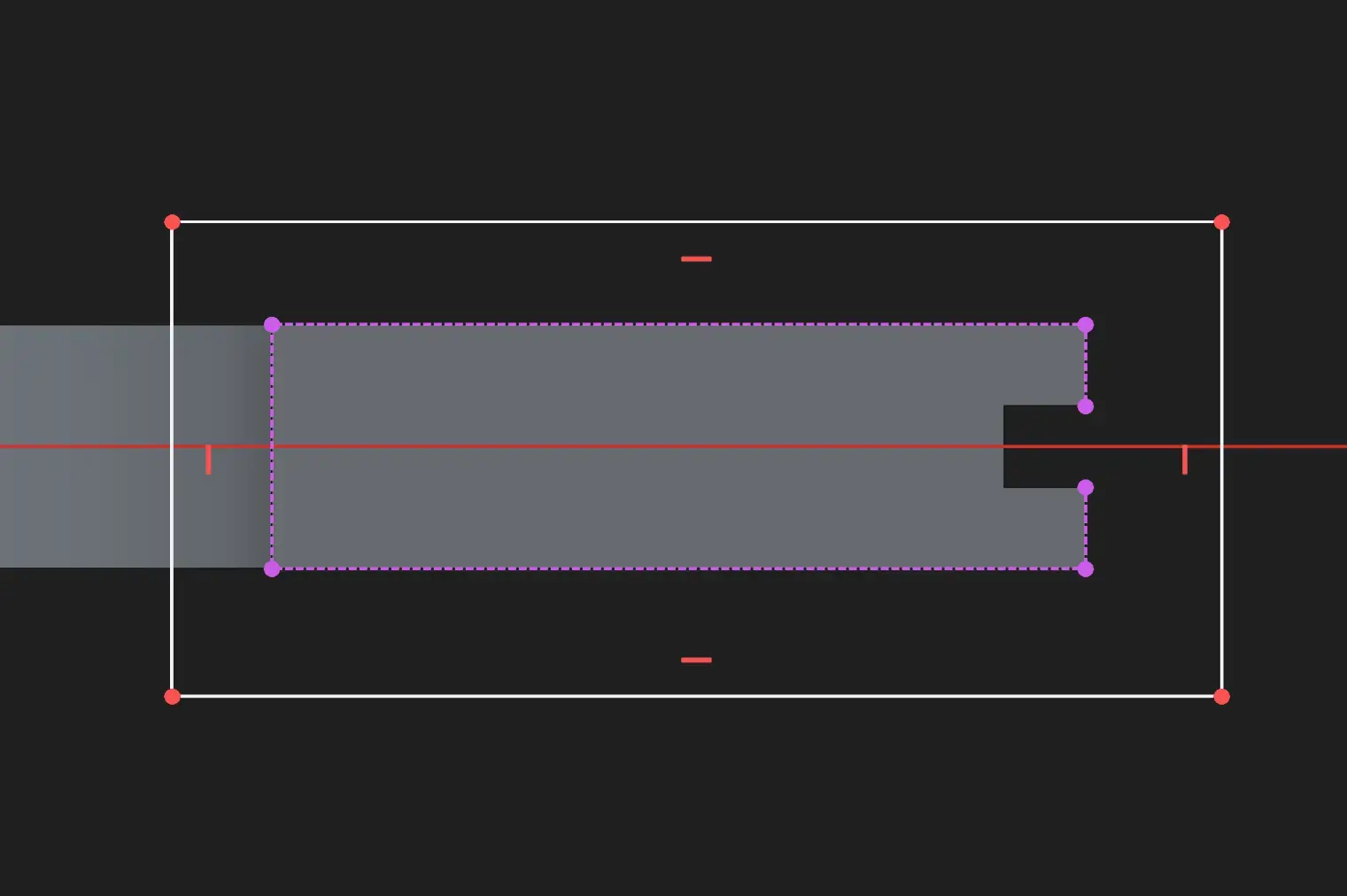
I click the top of the external geometry, then the top of the rectangle, then the vertical distance tool and insert 50 mm. FreeCAD can be very picky about the order how you select objects and tools 🙄
I try doing the same for the bottom distance, but for whatever reason it doesn’t work. After wasting some time, I close the project and open again and now it works 🤷♂
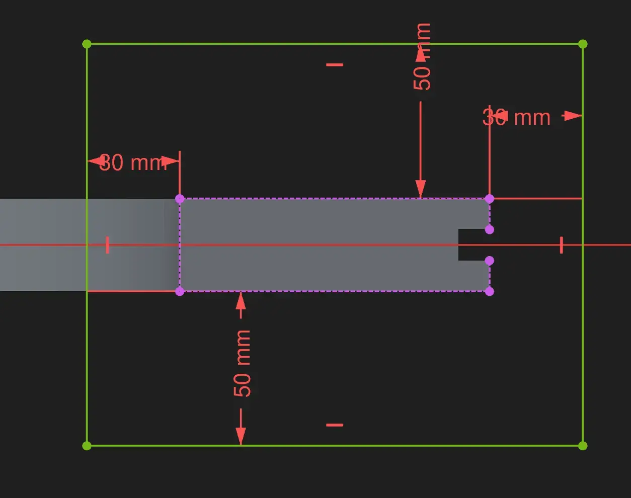
So, I try doing the same for the horizontal distances, but I don’t manage to, even after closing and opening again. So after consulting with Gemini, it suggests selecting the edges instead. I try that and it works 🤦This is so NOT intuitive. 😵
This is what it looks like:
I now exit the sketch and pick he Pad operation
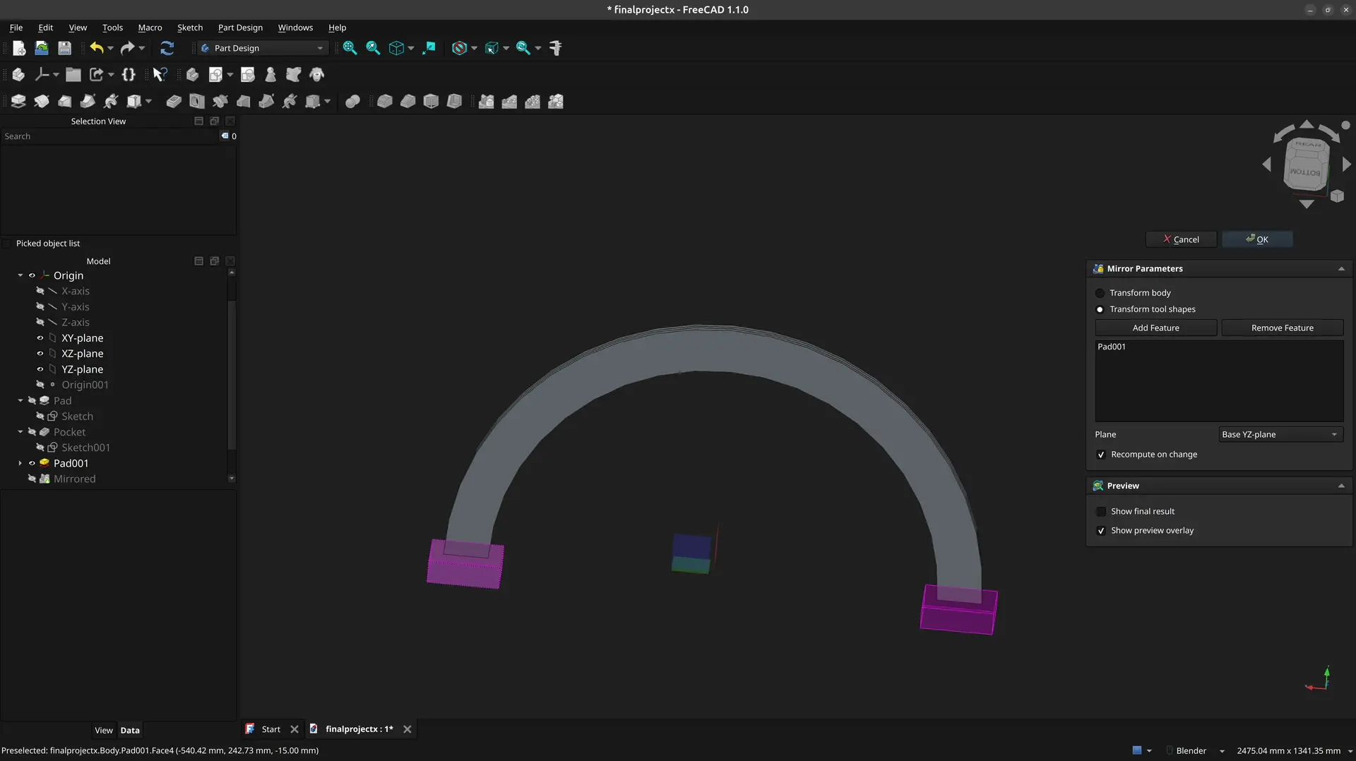
Now, instead of repeating everything again for the other side, I’ll use the mirror feature.
I move around the new part, and Ctrl click every face of it to have it all selected:
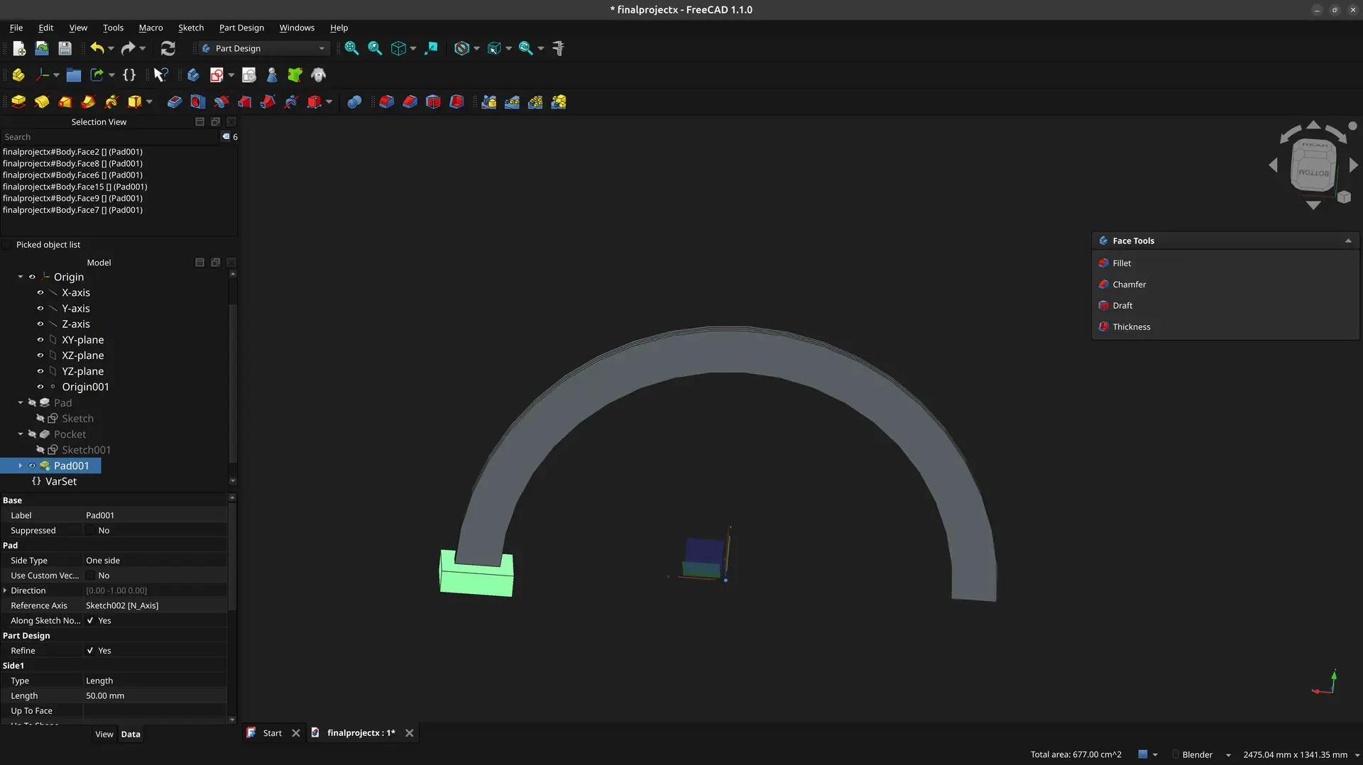
and pick the mirror tool:

It seemed to have guessed the correct mirror axis as the Base YZ-plane, but we could change it if it’s not what is wanted.
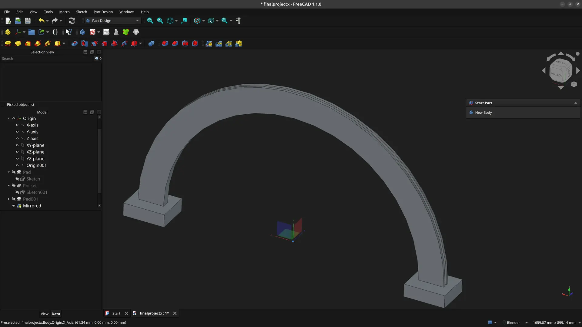
This part is now complete
Nuts and bolts pockets
There’s a hole tool in FreeCAD so let’s try to use it.
I need to create a point on the arch, so I eyeball it and then apply the distance constraint to the origin using an expression.
Next, want to set it at a specific angle, but it can’t be done directly. I need the help of construction lines. These lines are ignored when creating 3D shapes, they exist purely for math and constraints.
I toggle the construction geometry.:

An the join the point and origin with the line, so I can finally add the angle constraint.
I exit the sketch and pick the Hole feature and select one of the available bolts (it’s not important which) and select the depth as Through all
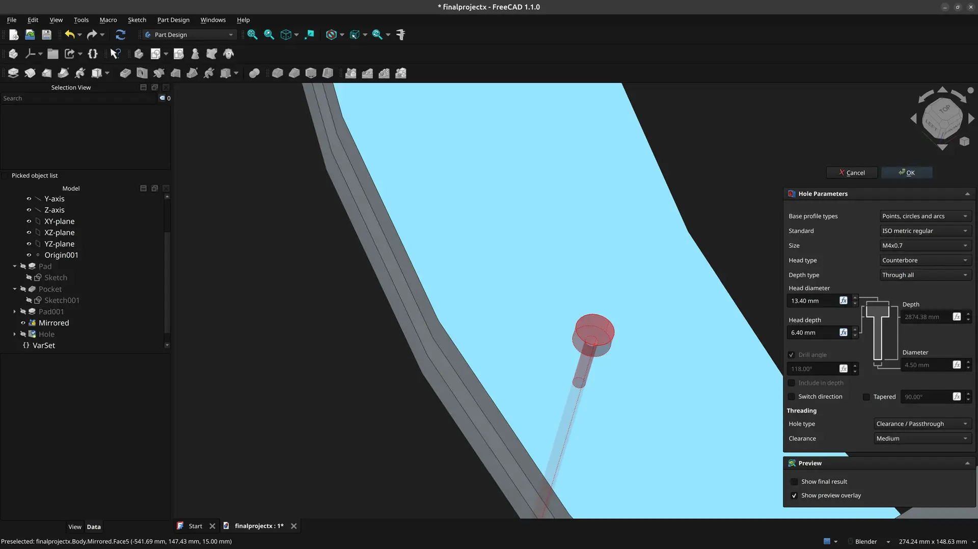
Sadly, this only works in one side, so I need to add the space for the nut on the other side.
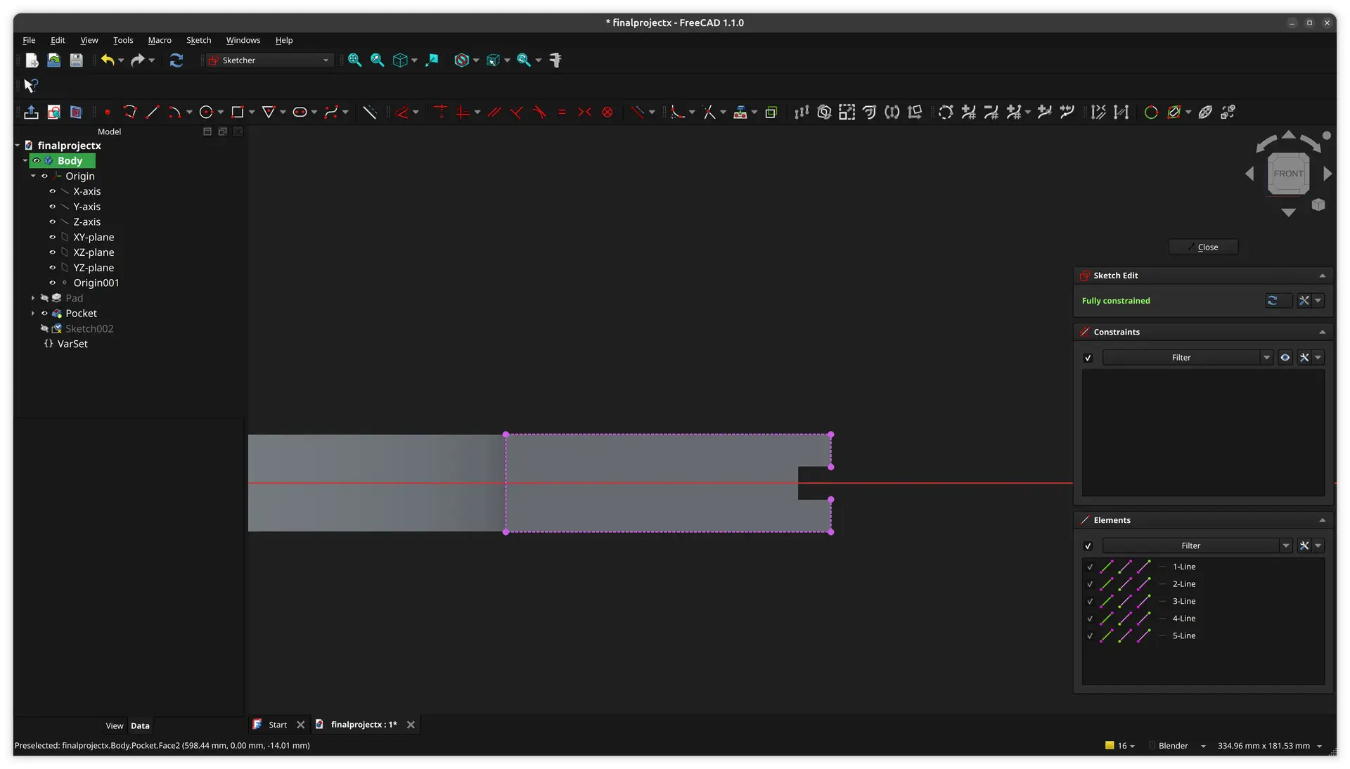
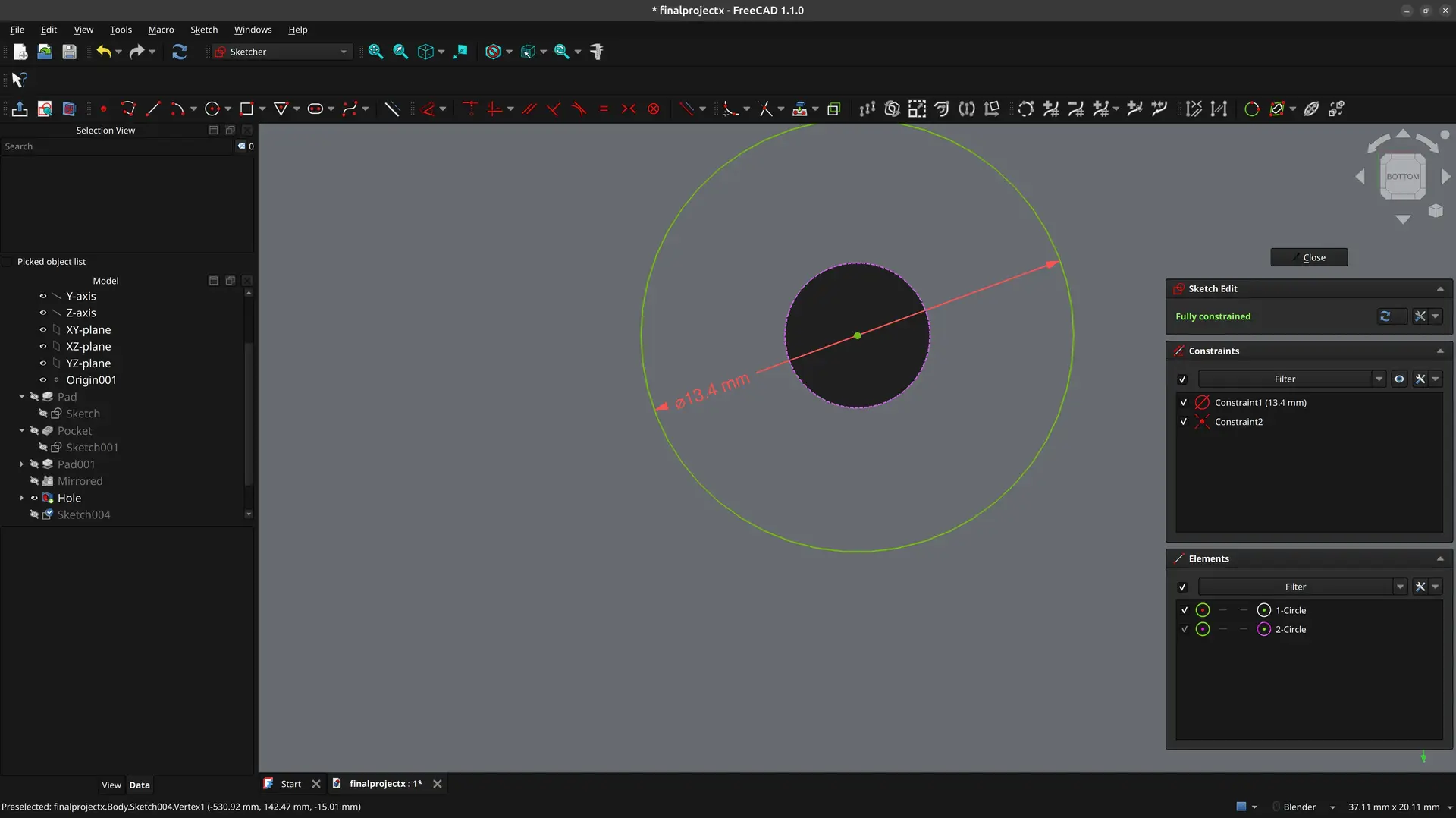
I rotate to the other side, select the face of the arch and create another sketch. Then I pull the hole with the external geometry, so I can fit a circle with the same center.
I define the same diameter as on the other side.
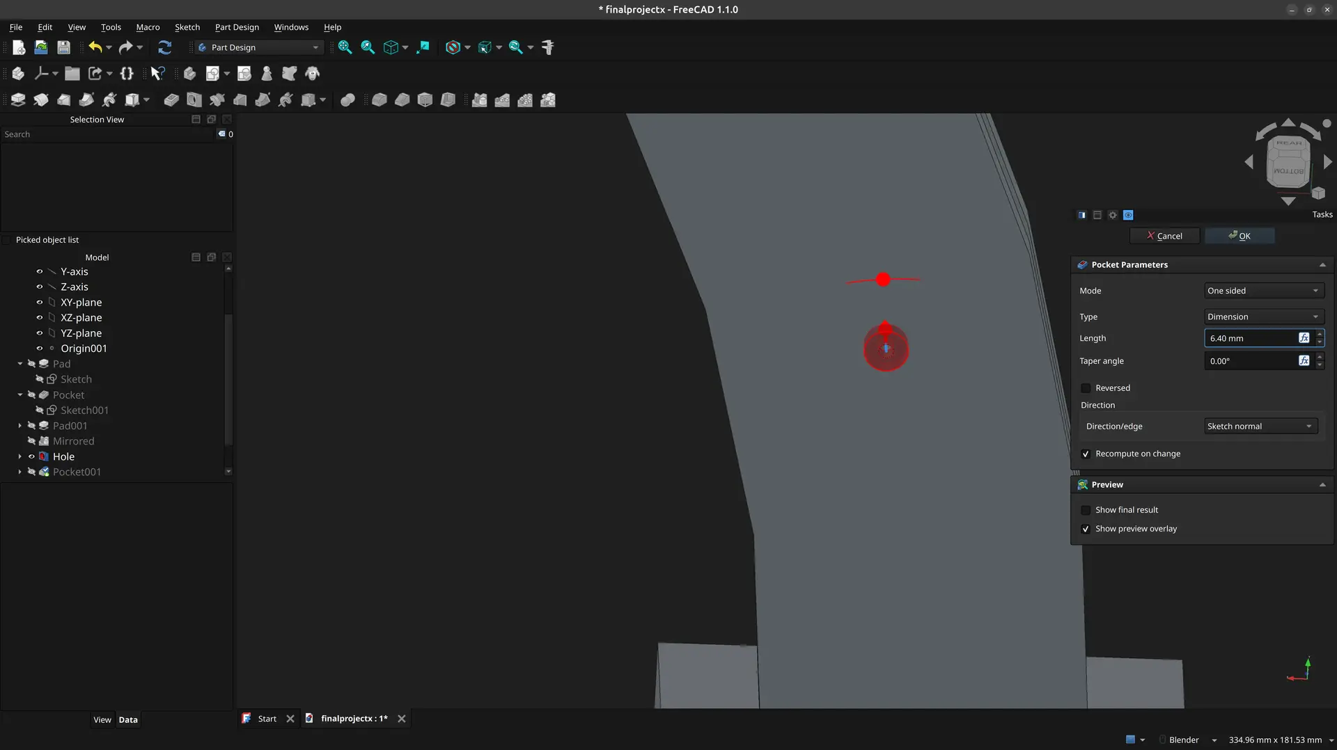
I exit the sketch, click the Pocket tool and set the same depth as the other side.
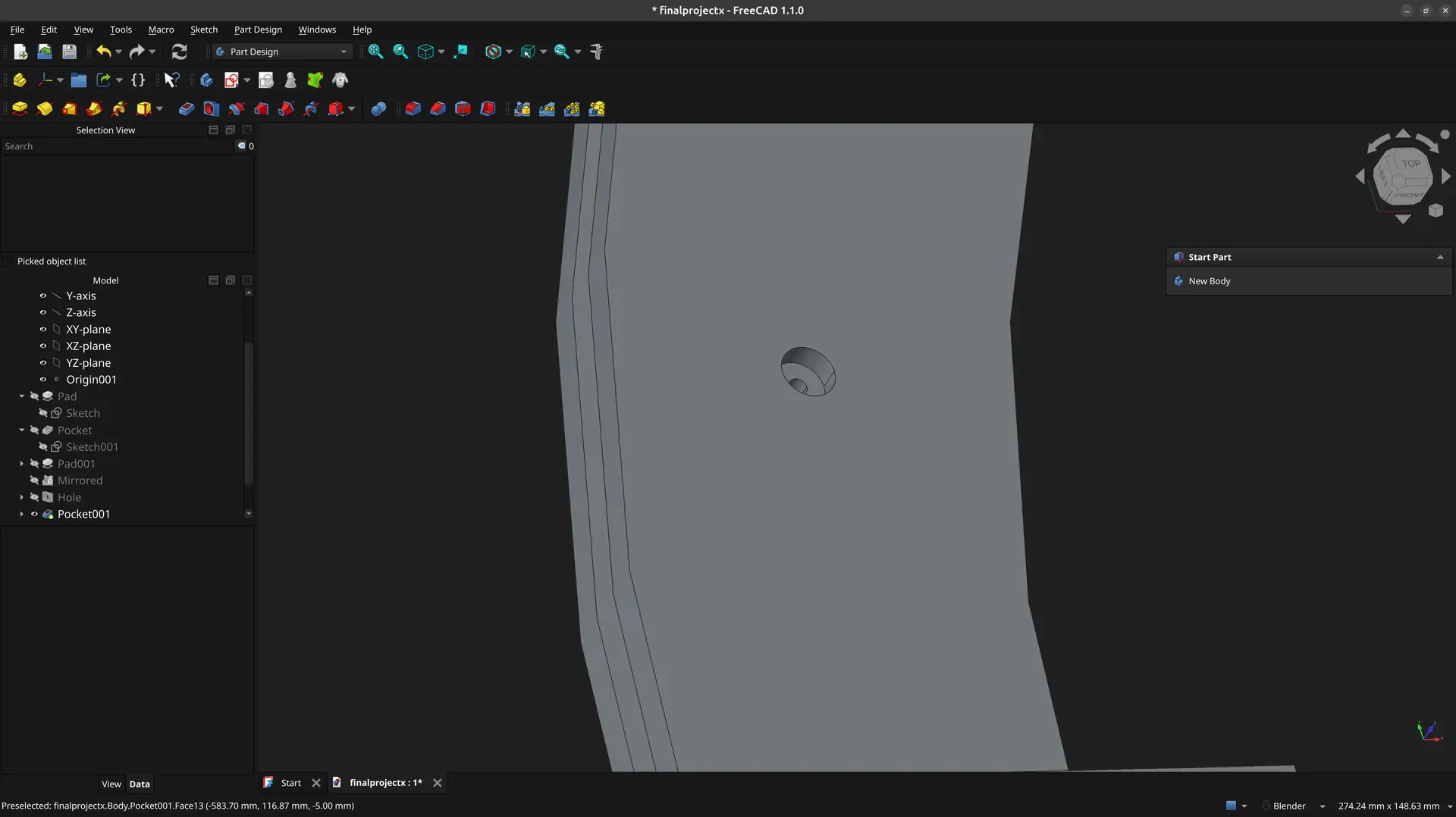
I now have the openings for the nut and bolt on both sides.
I need 10 more of these, so instead of repeating this 10 times, I’ll use the polar pattern.
I select the hole and he pocket in the tree view:
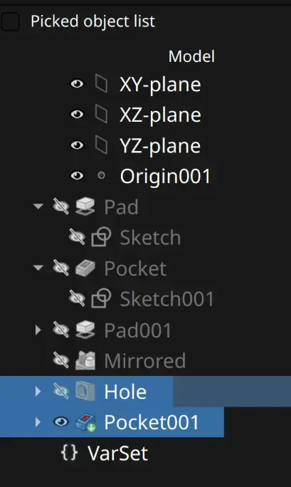
and click the Polar pattern tool

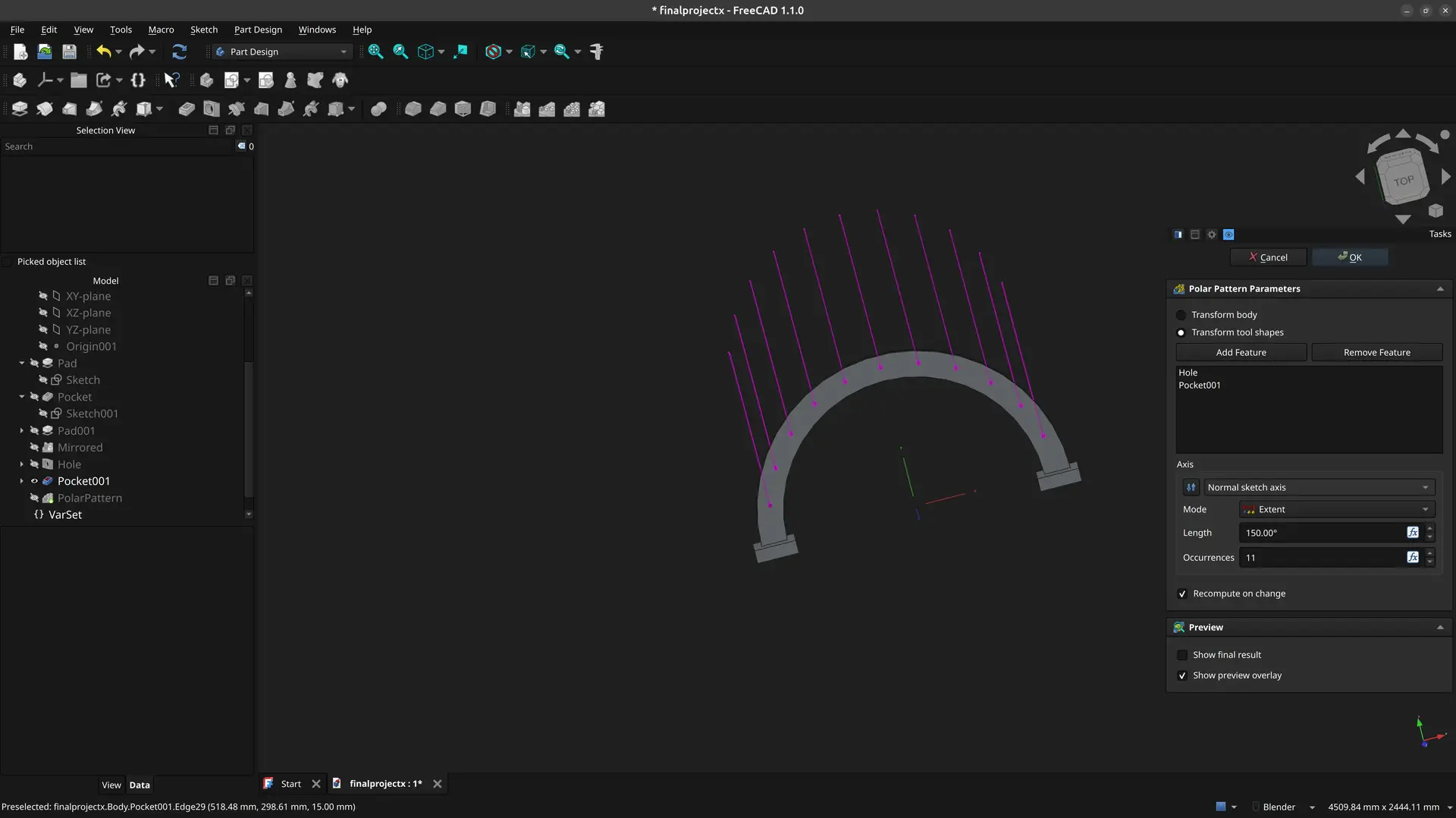
I choose 150º for length as I want to have a 15º margin on both ends, pick 11 occurrences total (it makes the angle between each to be 15º) click the reverse direction (it was going the wrong way):
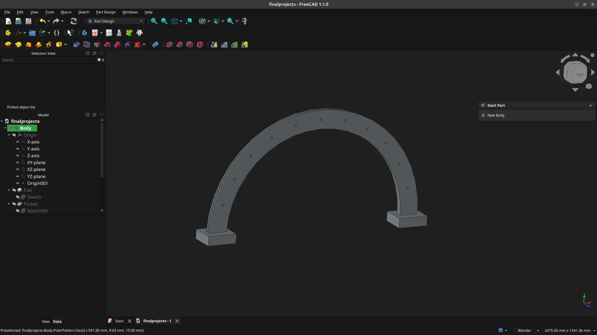
And finally 🙏 I have my object !
Conclusions
Compare the sheer amount of steps done in FreeCAD, with the simplicity of a single page of OpenSCAD !
I find that the code approach is far superior for me. Also when looking at the result, I find it much more understandable how one got to the final result and what needs to change.
Replacing the absolutes of OpenSCAD with a bunch of constraints in FreeCAD to avoid doing some math is generally a poor trade off.
Being text based, one can also see the evolution of a design in several versions of source control which you cannot do with a binary format.
In this exercise I just show FreeCAD’s Part Design workbench, but when exploring other workbenches, a lot of functionality seems repeated, but operating in a slightly different ways. It feels like there were several CAD programs and someone decided to put them all under one roof without trying to have a cohesive experience.
Things are often not very intuitive, which Gemini captured in this response when I was learning about mirror tools: «Ah, the FreeCAD Mirror tool strikes again. What you are experiencing is actually its default, highly annoying behavior: the standard Mirror tool only copies the geometry, not the constraints.» 🤷♂
It’s not all bad though. The number of tools available is comprehensive and there is community support for plugins and within FreeCAD one can also go beyond CAD and into CAM, and everyone is saying it’s getting better over the years.
One thing that’s way easier in FreeCAD (that I didn’t explore here) is applying chamfers and fillets as an afterthought, once the main design is done. In OpenSCAD that is usually more complex and has to be thought of from the beginning.
On the other hand OpenSCAD community also references some libraries to deal with these and other issues, but I didn’t yet explore these.
Finally there’s the debate on the engines these 2 use: FreeCAD uses OpenCascade which is B-Rep type, whereas OpenSCAD uses CGAL/OpenCSG which is CSG (Constructive solid Geometry) and is mesh based.
While mesh based approaches are fine for 3D printing, B-Rep is preferable for CAM where you have to set toolpaths, for example.
Ideally I would want the best of both worlds - a code base approach but that is good for CNC also.
Gemini pointed to a few code based OpenCascade alternatives:
- build123d (python based)
- CadQuery (python based)
- CascadeStudio (javascript based, can transpile OpenSCAD)
Too many options, too little time 😅, but I’d like to explore some of these alternatives at some point.