Laser Cutting
In this document I describe the steps of the construction kit I designed.
First try
Apparently I missed the note that one should not use Inkscpape’s clone tool to the parametric design because “it is not a real parametric software.” 😬
In any case, that was precisely what I used and it worked quite well for my objective. In the future I plan to use “real” parametric design in a tool like FreeCAD.
The basic shapes
I designed a rectangle and circle.
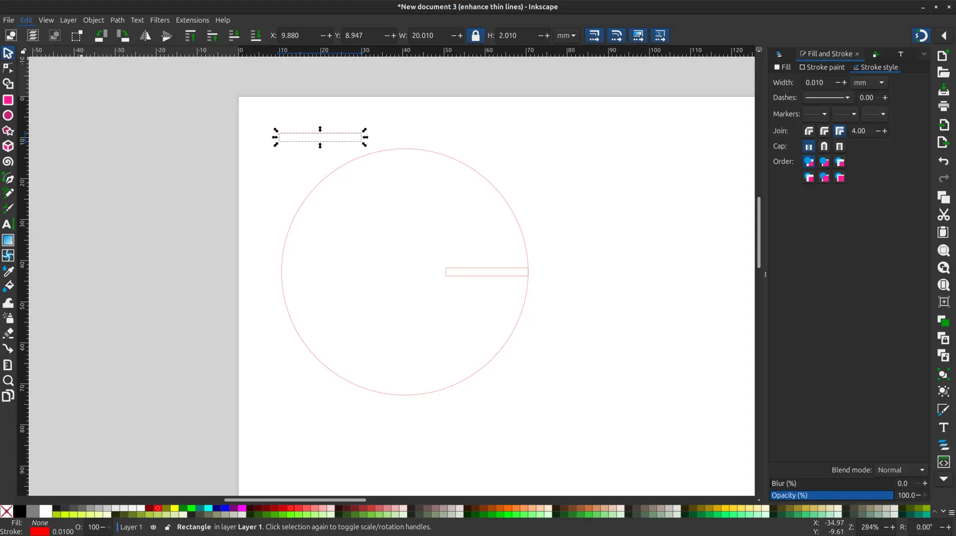
The clone hack
I used the Edit -> Clone -> Create clone tool to make a clone of the rectangle and aligned it with outer edge of the circle.
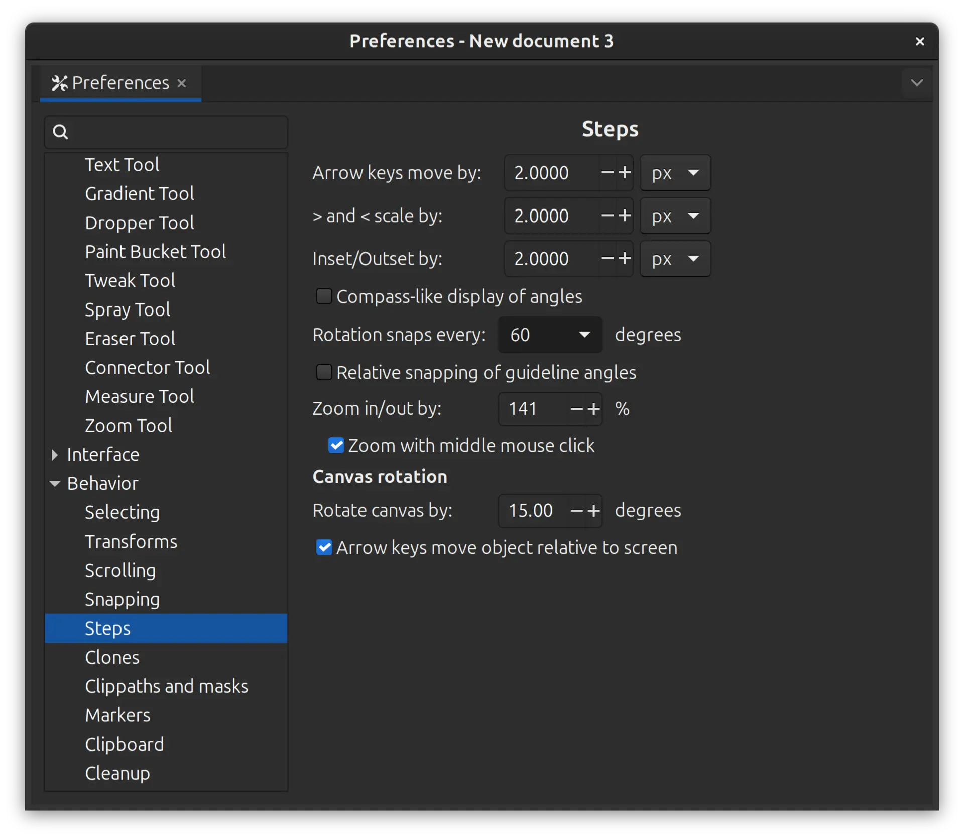
I then went into Edit -> Preferences -> Behavior -> Steps and changed the setting for Rotation snaps every __ degrees and changed it to the desired angle
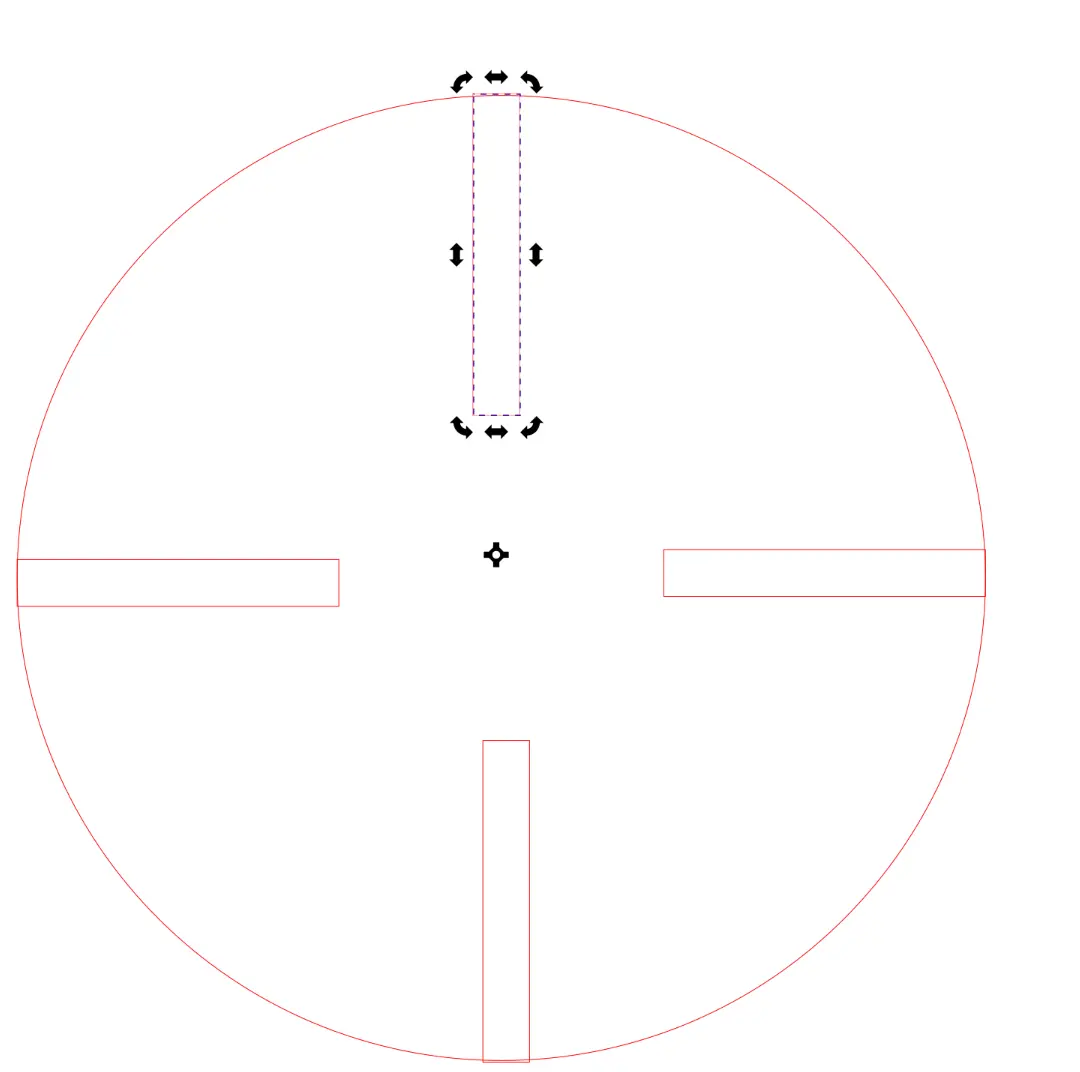
I cloned the object again, and double clicked the cloned object, and shifted the rotation point to match the circle center. While holding down the control key (to snap) I rotated the cloned object, which snaps to the previously defined angles, and repeated the process to have a complete object
I also experimented with one of the shapes to subtract the rectangle from the circle to achieve a clean cut. This can be done by selecting the circle and the rectangle, and then selecting Path -> Difference as seen here:
However, when doing so, the cuttings are no longer a clone, and if one changes the size of the original object, the clones changes shapes, but the unified path doesn’t, as seen here:
More shapes
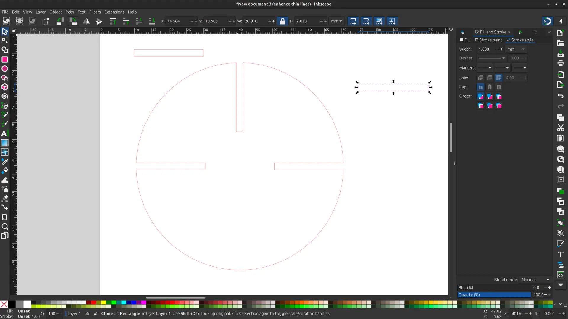
I copied the basic shape applying the previous pattern an added a couple more basic shapes.
Here is the final result:

The size of the cutting took into account the Kerf determined in the in the group assignment.
Hero shot
And here’s the end result:
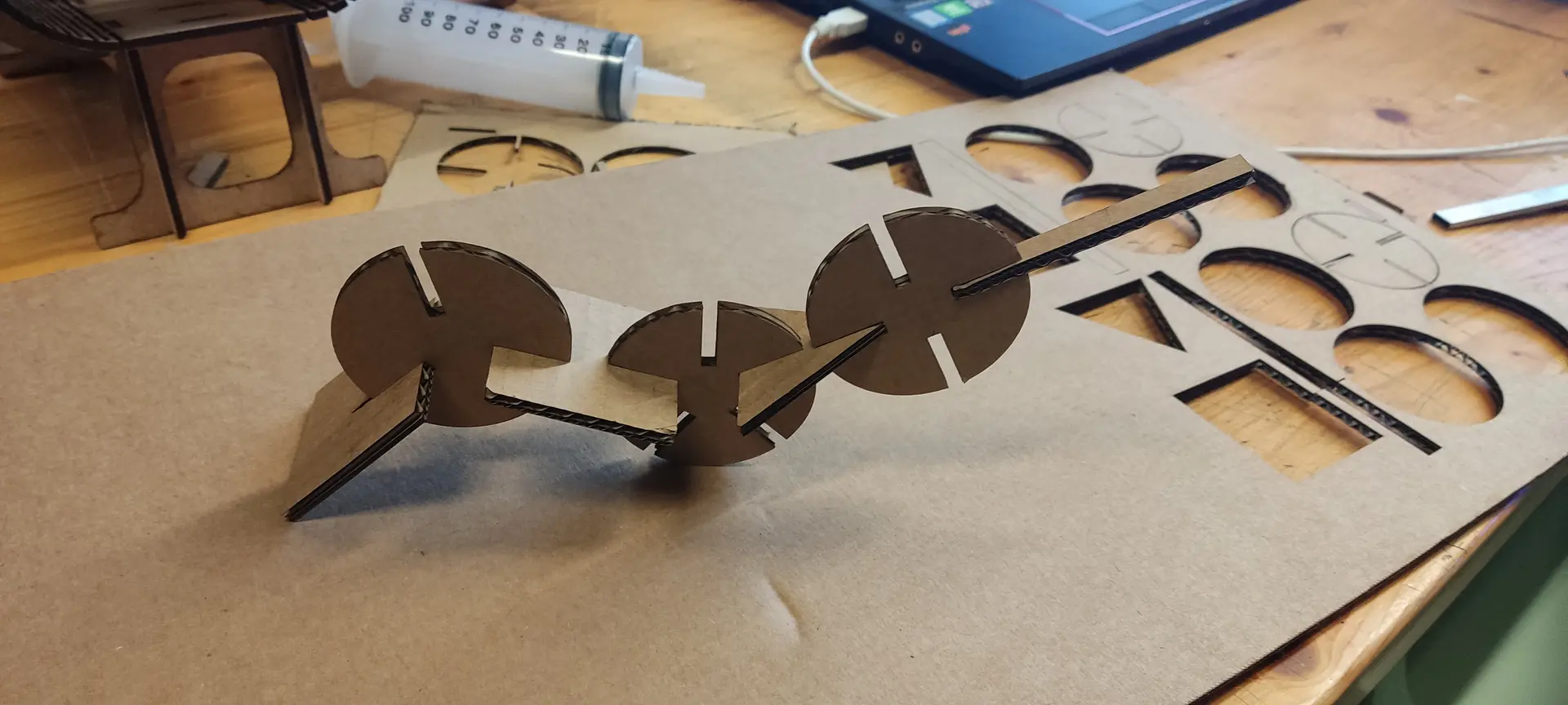
And here’s a video of it holding together:
All in all, I learned quite a bit about vector drawing and concepts I didn’t know previously
Second try
Because we weren’t supposed to use the clone tool, I had to redesign the pieces in a parametric way.
Since there is some repetition and the concept felt a bit “mathematical” in nature, and I like the predictability of code, I chose to redesign it using OpenSCAD.
Here’s a useful cheatsheet.
Designing the cut
One thing I noticed when I laser cutted my pieces is that having a bit of a chamfer would have been helpful to better fit the pieces together, so I designed the cut to include it.
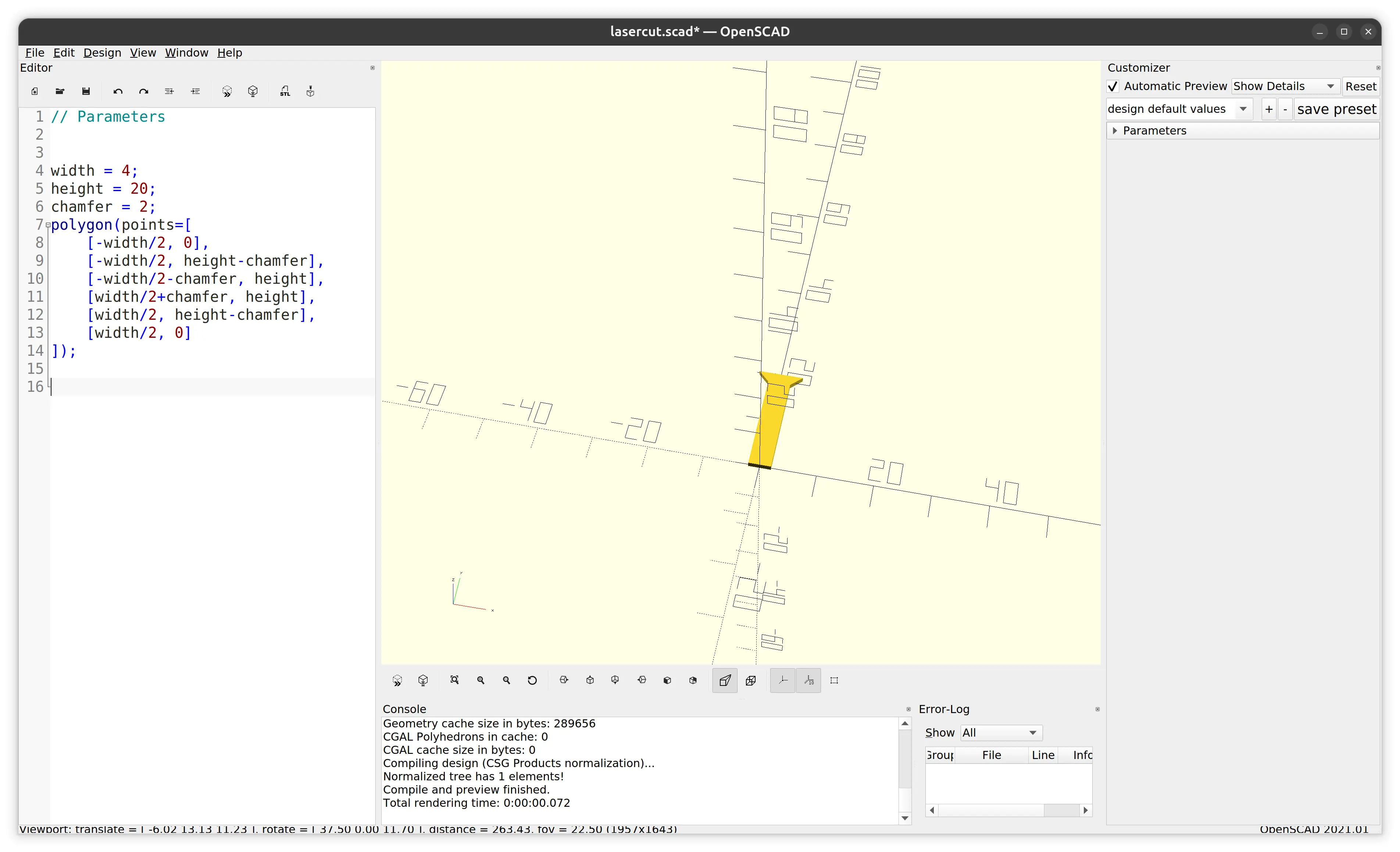
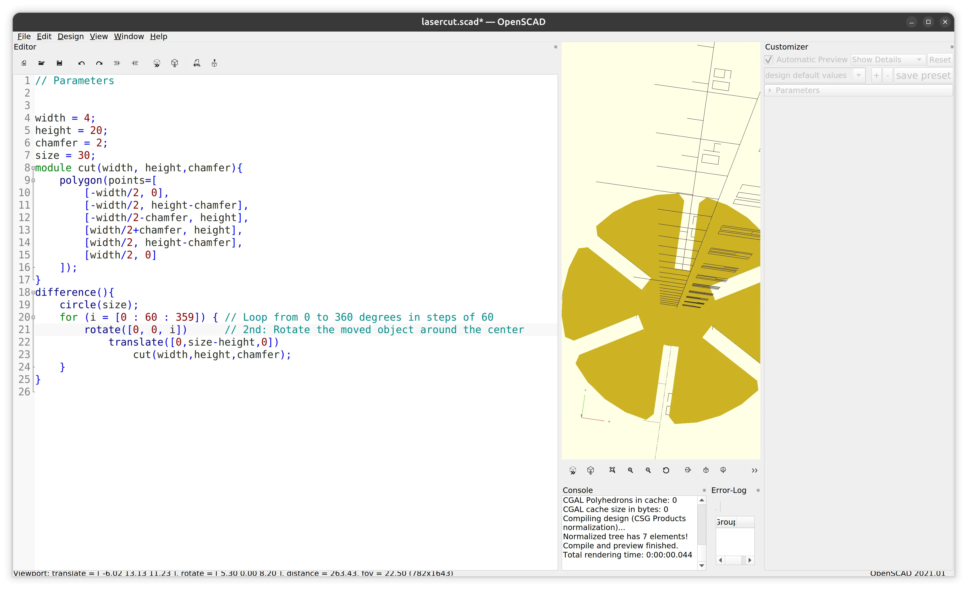
Designing the shape
Once I got the basic shape right, I modularized the cut so that it could be applied multiple times, and tried it out on a circle by applying rotation and a difference:
More shapes
Once I got that right, I also modularize the piece so that I could apply it multiple times, and I added a few more shapes around the plane:
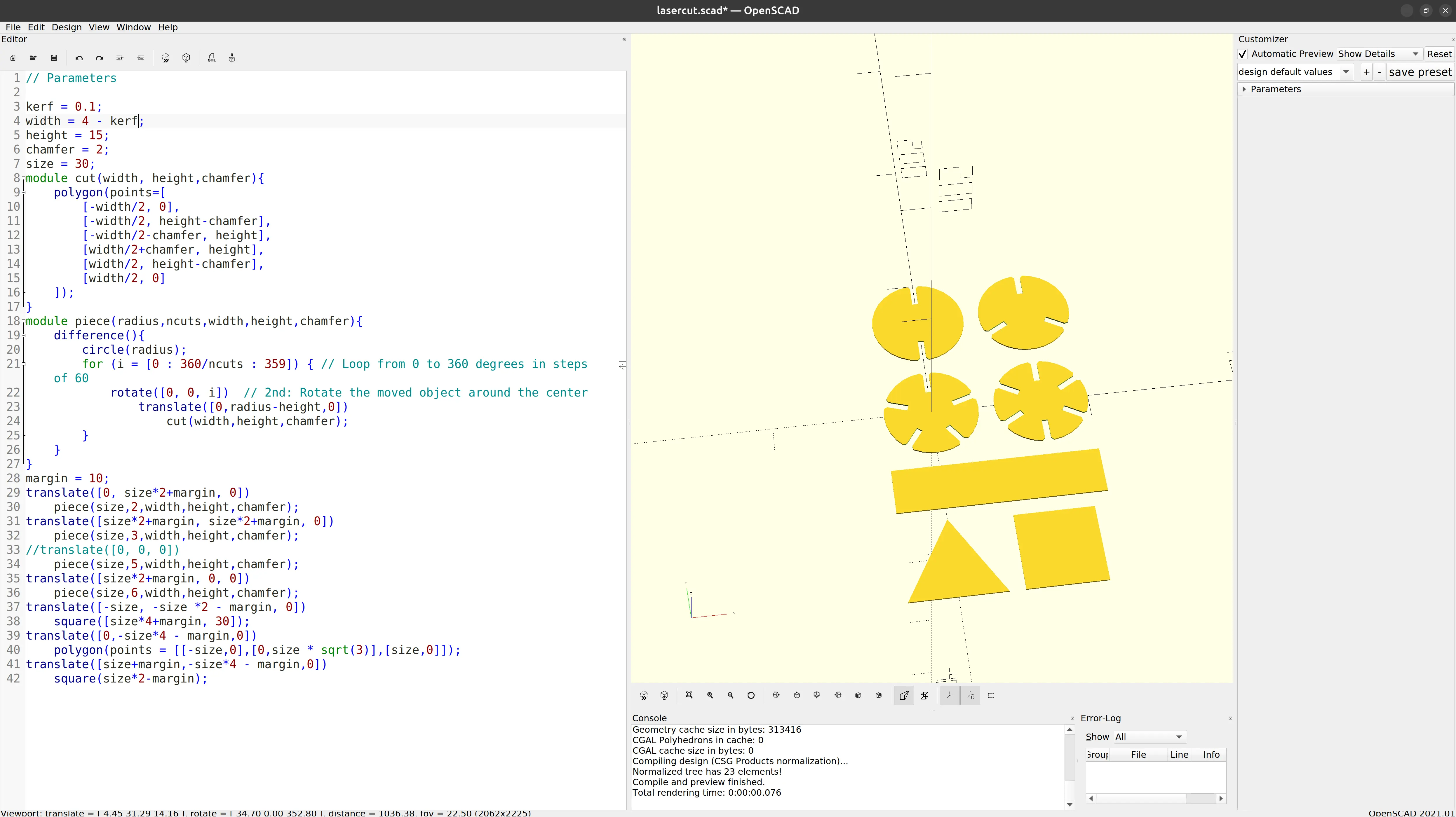
Testing with different parameters
We can see that the model is parametric, and I just have to change the kerf variable. For illustration purposes only, I change the width variable just so that the difference is visible to the naked eye:
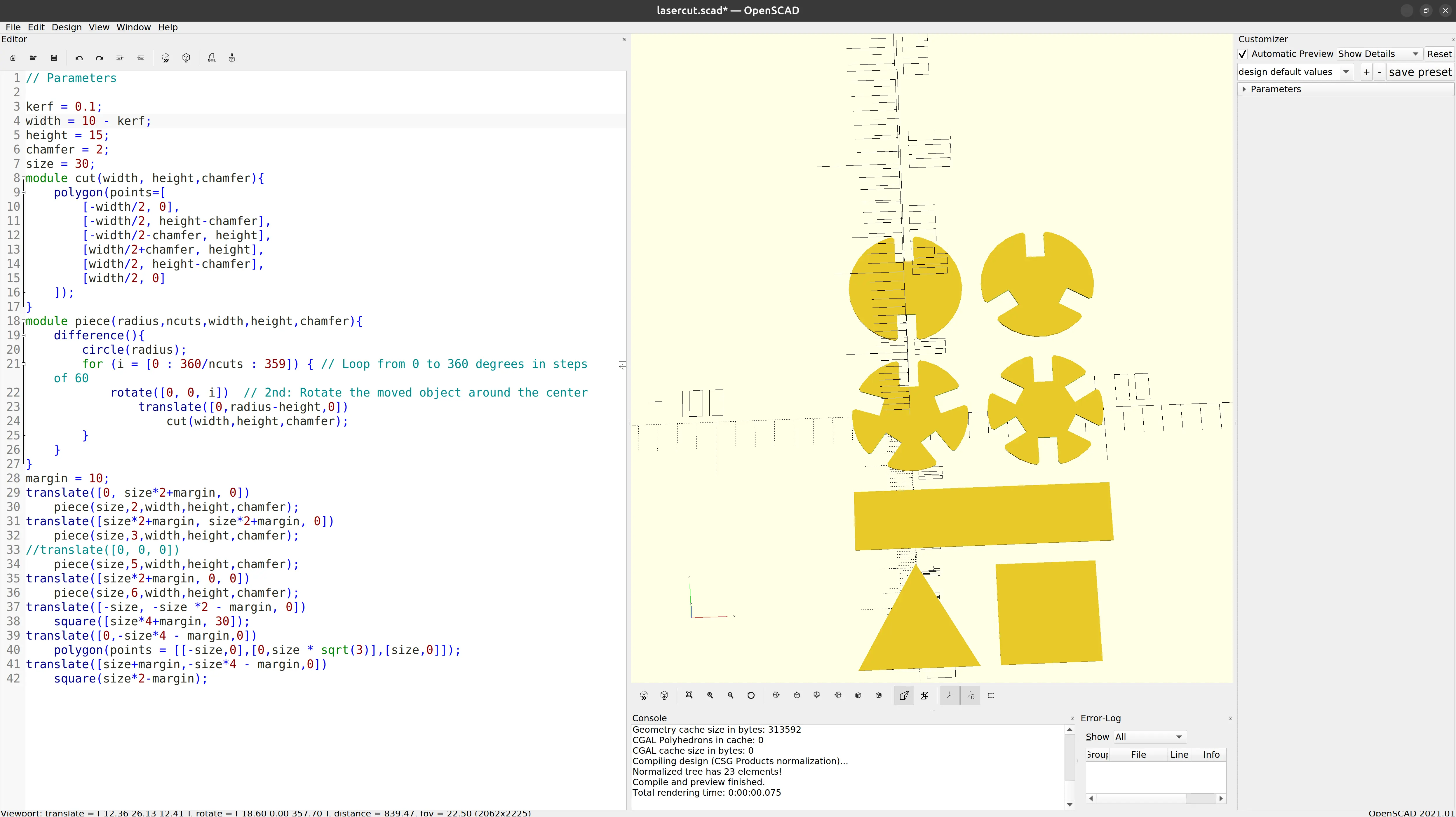
I move it back to 4 mm, which is the width of the cardboard material I was using, and leave the kerf at 0.1 mm.
Improving precision
One detail is that the OpenSCAD’s default “fragments variable” value is set for fast rendering, but we want smoother curves before exporting the final SVG. Here’s what it looks before, if we zoom in:
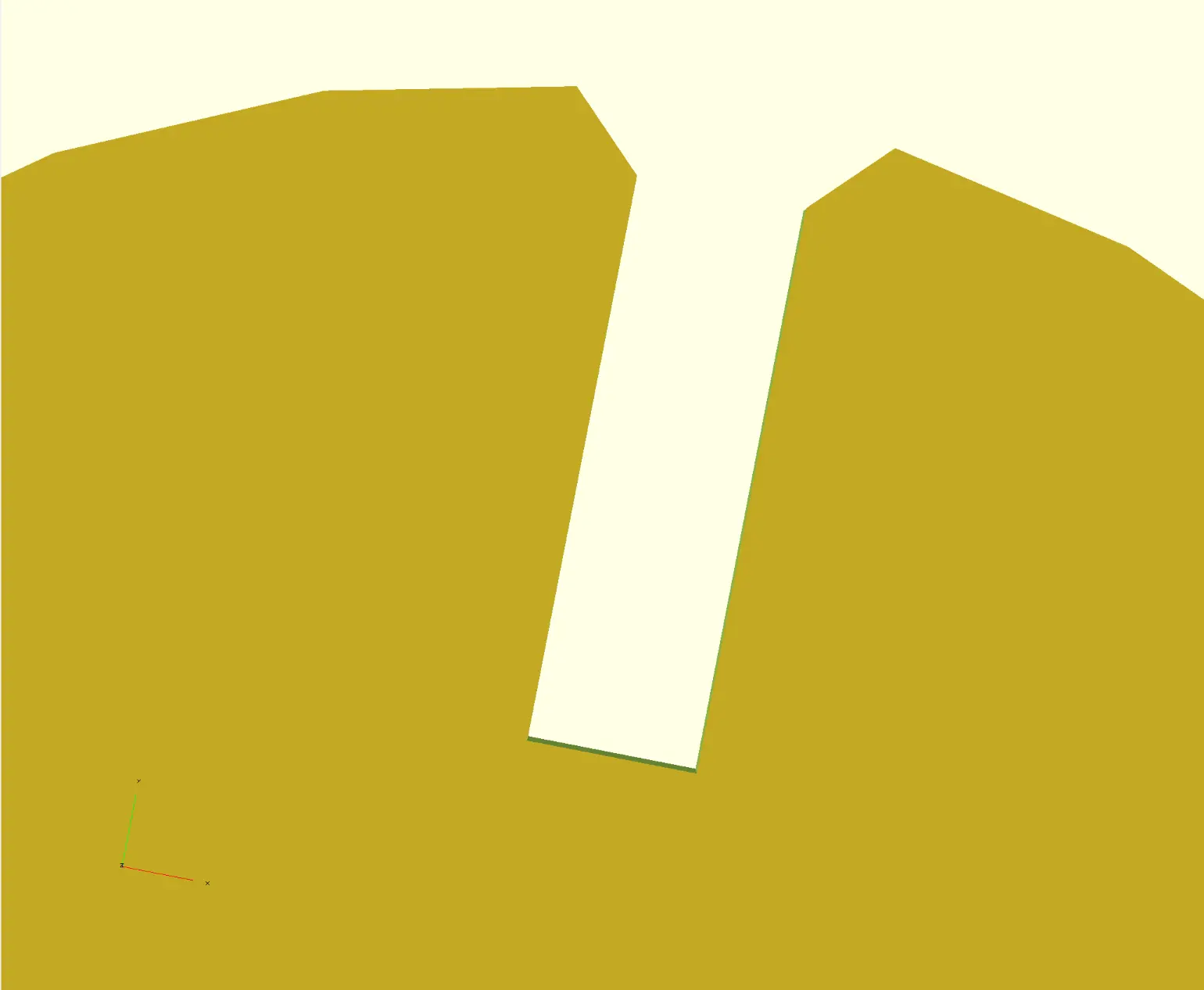
And if we make $fn = 360:

I then exported to SVG.
Cleanup
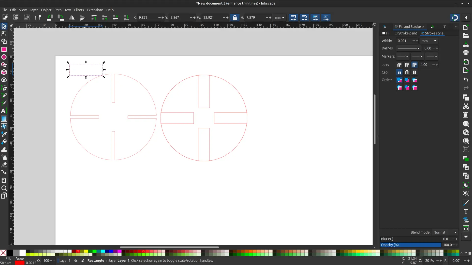
The SVG could be used directly by the laser cutter, but to make it easier with the default configuration, I open it in Inkscape, to do a basic cleanup.
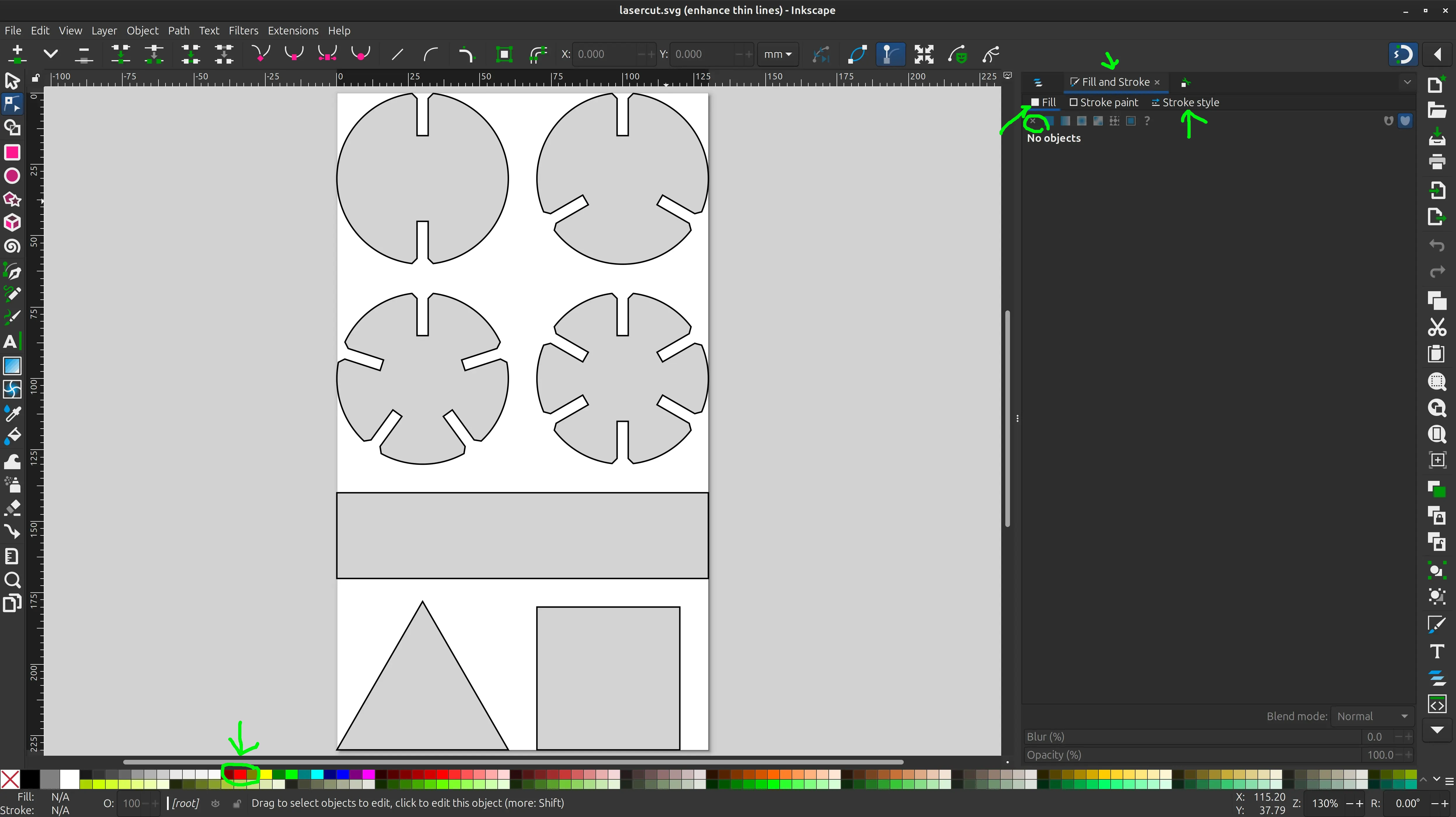
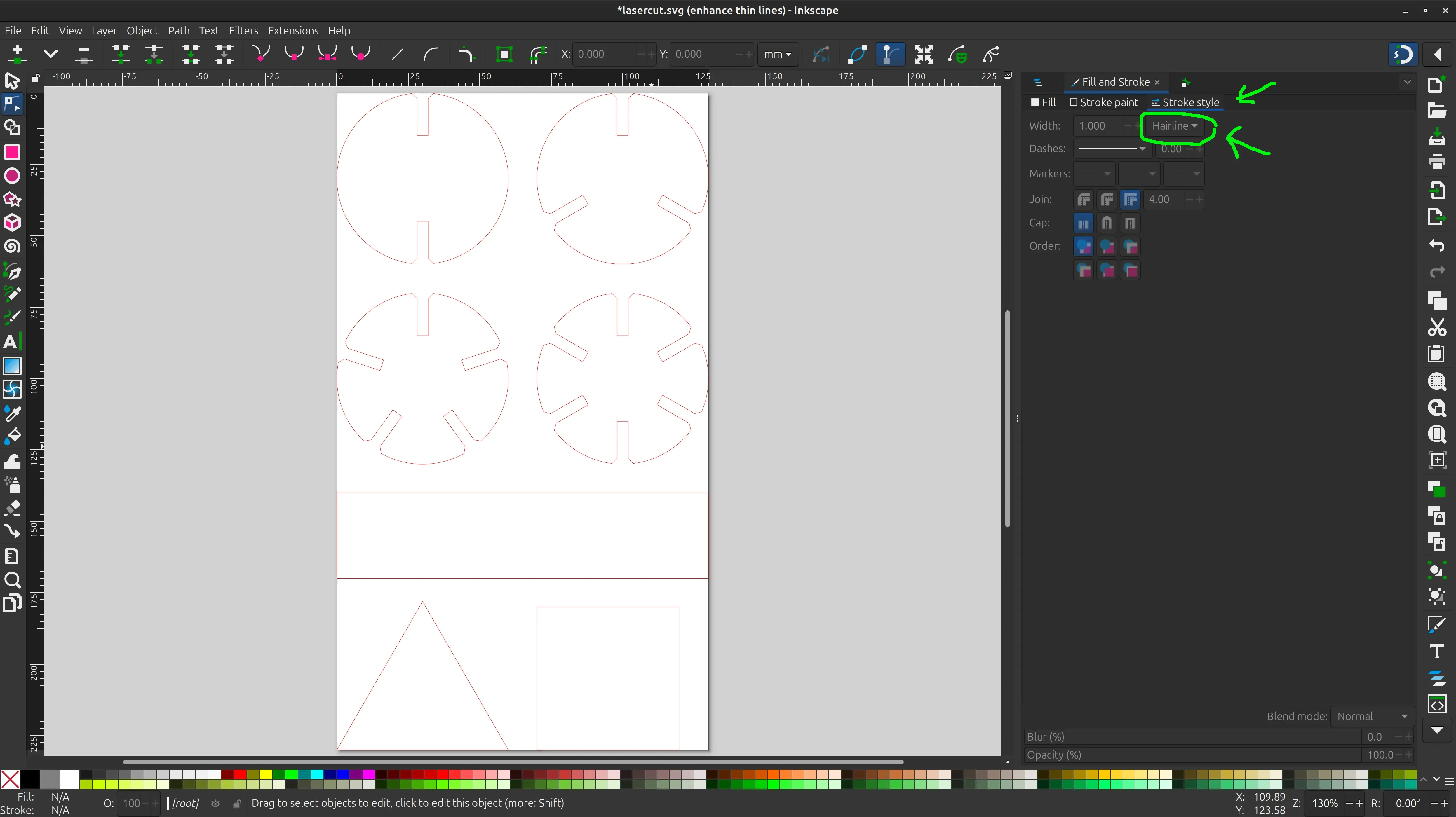
I click on the shape, select “No paint” in the “Fill” tab, select “Hairline” in the “Stroke style” tab, and shift click on red at the bottom to set the red color that the laser cutter sofware expects.
And here’s what it looks like:
Finally I click “Save as” and pick “Plain SVG”. It’s now ready to cut.
Files
1st try with inkscape
openscad file
openscad svg output
openscad svg clean