3D Printing
3D Printing Group Assignment
The group assignment can be seen here
Learnings from testing 3D printers
- printers vary in sizes, print quality and speed
- different filaments produce different results
- Some brands are more open source (like Prusa), while others seem to move more to closed source (like Bambu). Luckily there’s still some community effort to support closed source ones
- There are many, many parameters that can be tweaked, and figuring out why print quality is not great is a challenge.
- Most 3D printers, can’t print “int the air” and need to have supports when angles exceed a certain angle (hangovers) or both edged of a piece are too far apart (bridging)
- Whereas in laser cutting Kerf accounted for extra material removed, in 3D printing the opposite occurs and we he have to take into account horizontal expansion
3D Printing Individual Assignment
Fidget ring
While browsing other peoples designs, I found this Hyper fidget ring
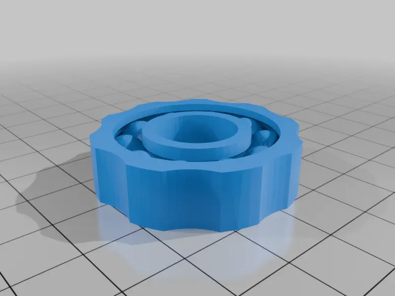
This is something that could not be easily made subtractively because the empty spaces between each spheres are not easily reachable.
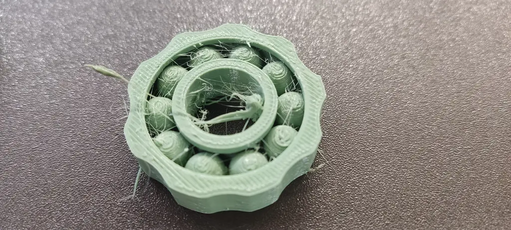
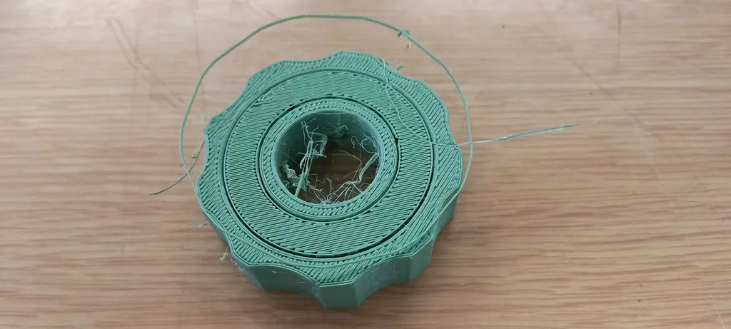
I tried printing on the Prusa, but the results were quite unsatisfactory.
This is the print without supports.
The top view:
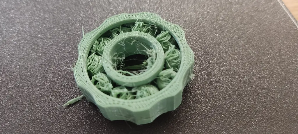
Bottom view: 😱
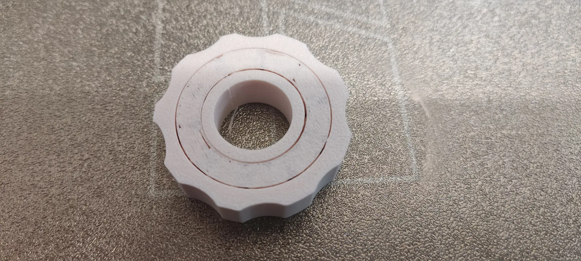
I tried a second run, where I increased the object size by 50% and added bottom support.
The top view:
The bottom view.
The results were unsatisfactory and the bottom support was impossible to remove 😞
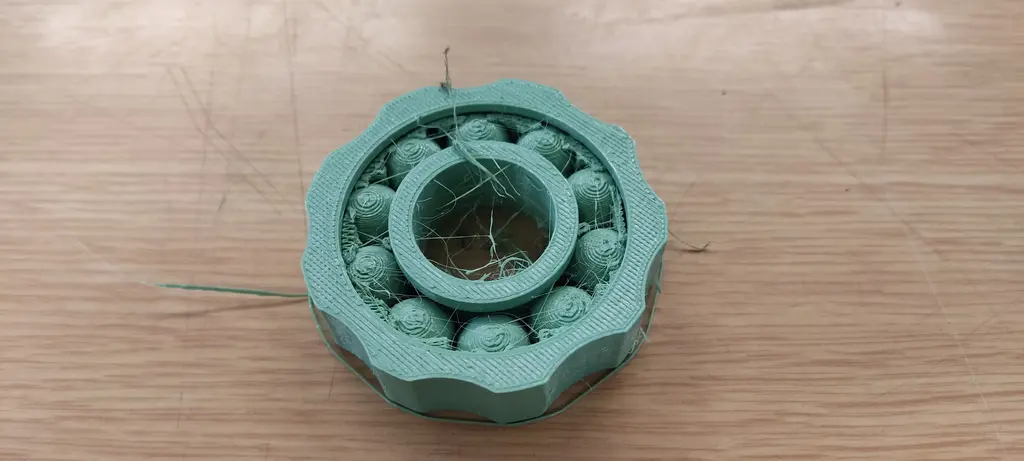
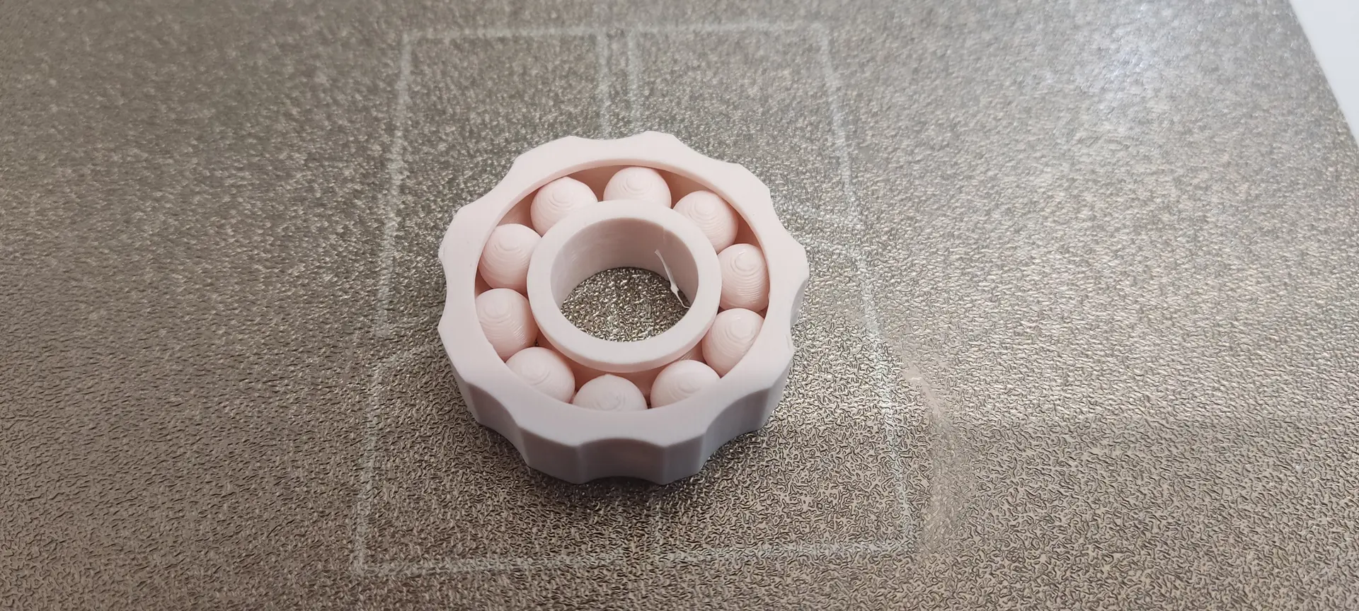
I did one last try with the Bambu, at the original size, and here are the results.
Top view:
Bottom view, with support.
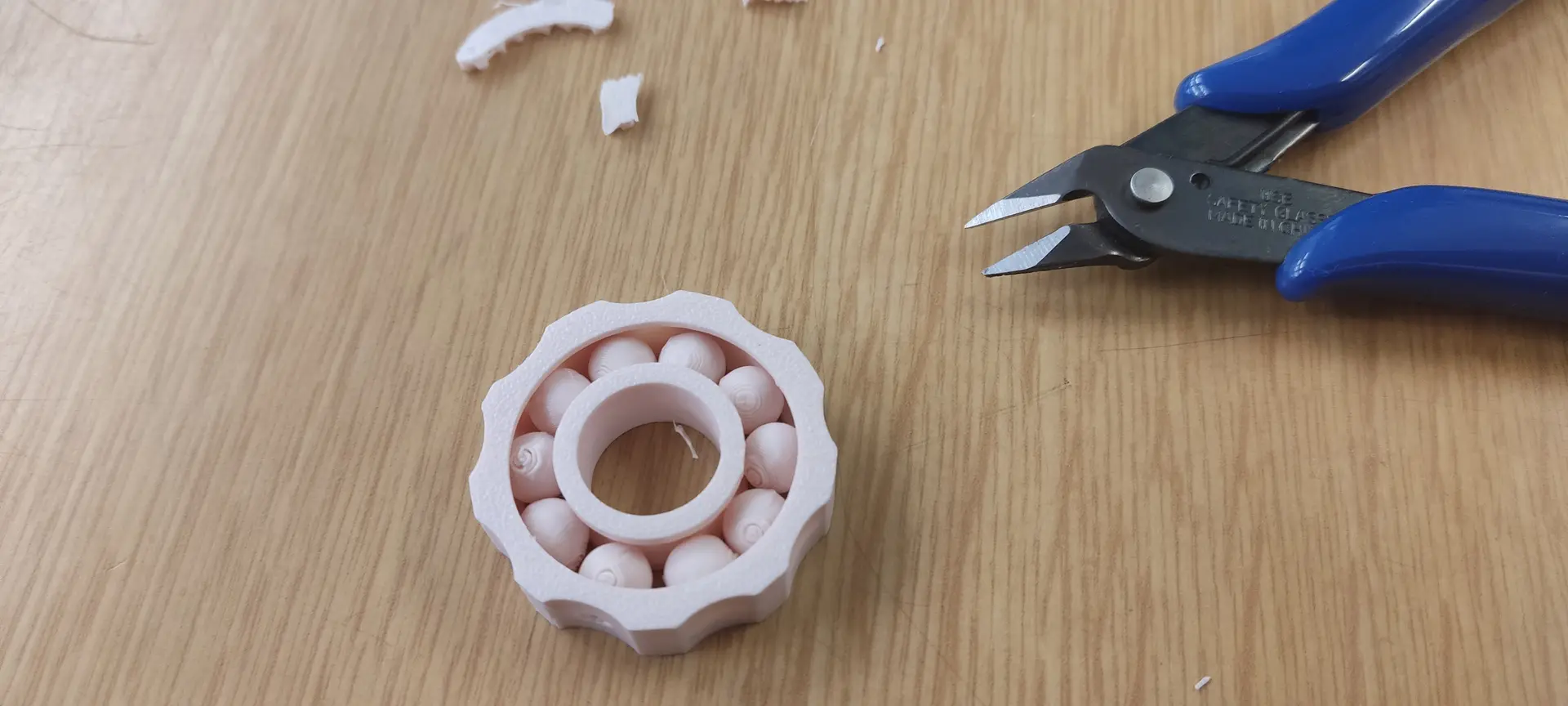
Bottom view, without support. The quality was good, and although the support was tricky to remove, it eventually snapped in a couple of sections, and the spheres could move freely.
GEB solid
For my second piece I want to replicate something similar to the cover image of the book Gödel, Escher, Bach: an Eternal Golden Braid

Given that one can use the python console of FreeCAD to execute operations, I decided to experiment with having the code generated by an AI, which is something they are good at.
I used ChatGPT for this.
In FreeCAD I enabled View -> Panels -> Python Console and In each interaction I copied the code generated into the console, executed and visually inspected the result.
After a few interactions to fix the right projections and “ghost” artifacts, we finally reached a satisfactory result.
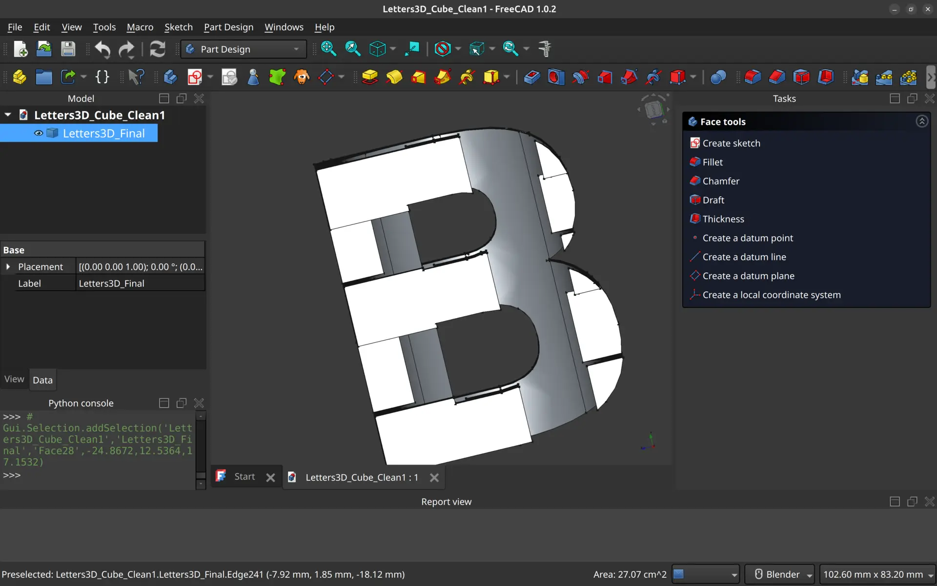
Here’s what it looks like.
View from the front:
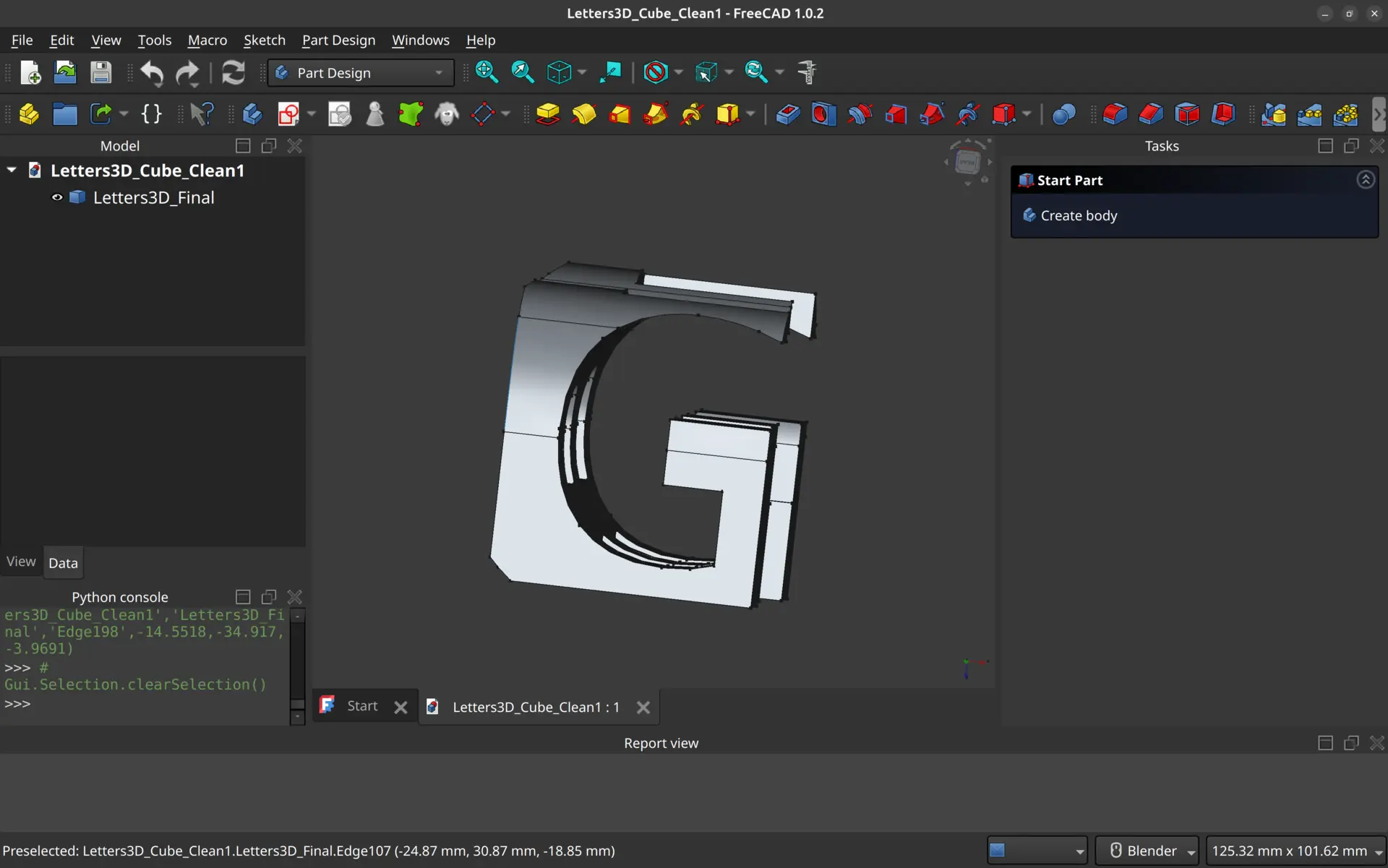
View from the side:
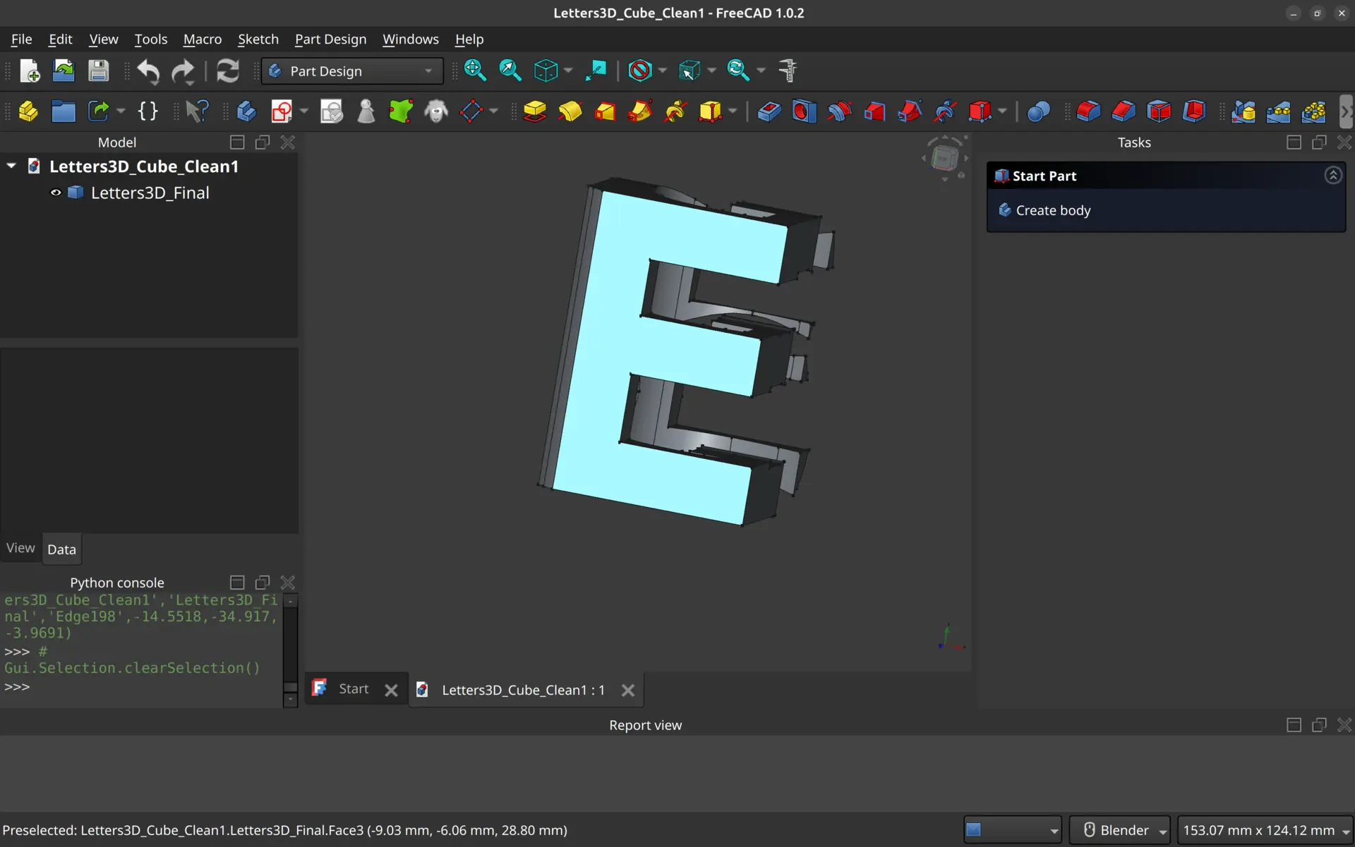
View from the top:
Here’s the final code that generated the object. This code is parametric, meaning you can tweak the letters, but obviously, not all letter intersections will produce good, printable results.
import FreeCAD as App
import Draft
import Part

# --------------------------
# PARAMETERS (adjust here)
# --------------------------
cube_size = 100             # Cube size in mm
font_path = "/usr/share/fonts/truetype/dejavu/DejaVuSans-Bold.ttf"
font_size = 70              # Base font size; will auto-scale slightly
letter_top = "E"            # Top view (XY)
letter_front = "G"          # Front view (XZ)
letter_side = "B"           # Side view (YZ) - only its holes will be carved

# --------------------------
# CREATE DOCUMENT
# --------------------------
doc = App.newDocument("Letters3D_Parametric")

# --------------------------
# CREATE CENTERED CUBE
# --------------------------
cube = Part.makeBox(cube_size, cube_size, cube_size)
cube.translate(App.Vector(-cube_size/2, -cube_size/2, -cube_size/2))

# --------------------------
# HELPER: CREATE LETTER VOLUME
# --------------------------
def letter_volume(letter, plane):
    # create Draft ShapeString
    txt = Draft.makeShapeString(String=letter, FontFile=font_path, Size=font_size)
    App.ActiveDocument.recompute()
    shape = txt.Shape.copy()

    # remove ShapeString object
    App.ActiveDocument.removeObject(txt.Name)

    # outer face only (holes handled separately if needed)
    outer_face = Part.Face(shape.Wires[0:1])

    # center face on origin
    bbox = outer_face.BoundBox
    center = bbox.Center
    outer_face.translate(App.Vector(-center.x, -center.y, -center.z))

    depth = cube_size * 2

    # rotate/place for each plane
    if plane == "XY":      # Top
        outer_face.translate(App.Vector(0,0,-cube_size/2))
        extrude_dir = App.Vector(0,0,depth)
    elif plane == "XZ":    # Front
        outer_face.rotate(App.Vector(0,0,0), App.Vector(1,0,0), -90)
        outer_face.translate(App.Vector(0,-cube_size/2,0))
        extrude_dir = App.Vector(0,depth,0)
    elif plane == "YZ":    # Side
        outer_face.rotate(App.Vector(0,0,0), App.Vector(0,1,0), 90)
        outer_face.translate(App.Vector(-cube_size/2,0,0))
        extrude_dir = App.Vector(depth,0,0)

    vol = outer_face.extrude(extrude_dir)
    return vol, shape

# --------------------------
# CREATE MAIN LETTER VOLUMES
# --------------------------
vol_top, _ = letter_volume(letter_top, "XY")
vol_front, _ = letter_volume(letter_front, "XZ")
vol_side, shape_side = letter_volume(letter_side, "YZ")

# --------------------------
# INTERSECT WITH CUBE
# --------------------------
main_cube = cube.common(vol_top).common(vol_front).common(vol_side)

# --------------------------
# CARVE ONLY THE HOLES OF SIDE LETTER
# --------------------------
if len(shape_side.Wires) > 1:
    holes = shape_side.Wires[1:]
    faces = [Part.Face(w) for w in holes]
    cut_face = faces[0].fuse(faces[1:]) if len(faces) > 1 else faces[0]

    # center
    bbox = cut_face.BoundBox
    center = bbox.Center
    cut_face.translate(App.Vector(-center.x, -center.y, -center.z))

    # rotate & extrude along X (YZ plane)
    cut_face.rotate(App.Vector(0,0,0), App.Vector(0,1,0), 90)
    cut_face.translate(App.Vector(-cube_size/2,0,0))
    depth = cube_size * 2
    cut_vol = cut_face.extrude(App.Vector(depth,0,0))

    # subtract holes
    final_shape = main_cube.cut(cut_vol)
else:
    final_shape = main_cube

# --------------------------
# ADD FINAL OBJECT
# --------------------------
final_obj = doc.addObject("Part::Feature", "Letters3D_Final")
final_obj.Shape = final_shape
App.ActiveDocument.recompute()

print("Done! Letters carved with B holes removed properly.")
And after all the interactions to fine tune this code, here’s the prompt that should generate it:
Generate a fully parametric FreeCAD Python script that creates a solid cube and carves letters from orthogonal faces with these rules:

1. Cube size is adjustable via a parameter.

2. Letters are fully adjustable via parameters: `letter_top`, `letter_front`, `letter_side`.

3. Top face (XY) shows `letter_top`, front face (XZ) shows `letter_front`, side face (YZ) shows `letter_side`.

4. The cube remains thick and printable; only the inner holes of `letter_side` (side letter) are carved out.

5. Automatically scales letters to fit the cube while maintaining proportions.

6. Remove all Draft `ShapeString` objects so only the final solid remains.

7. Include clear comments for each step: creating letters, positioning, extruding, intersecting, carving holes, and final object creation.

8. Include a line to recompute the document and optionally export as STL."
Given the superior quality of the Bambu printer over the Prusa, I decided to use the first one.
Disappointingly, the Bambu Studio, which is the official software for the printer is not available for Linux, and the PrusaSlicer had no settings for this print either.
Luckily I learned about Orca Slicer which is opensource and available for Linux and supports this and other printers.
On the advice of our local instructor, we used all the default settings for the printer and filament (PLA in this case) and tweaked the support parameters as follows:
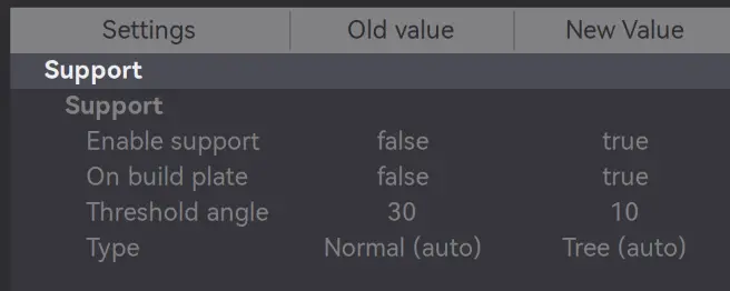
Here’s where we tweaked and what it looks like:
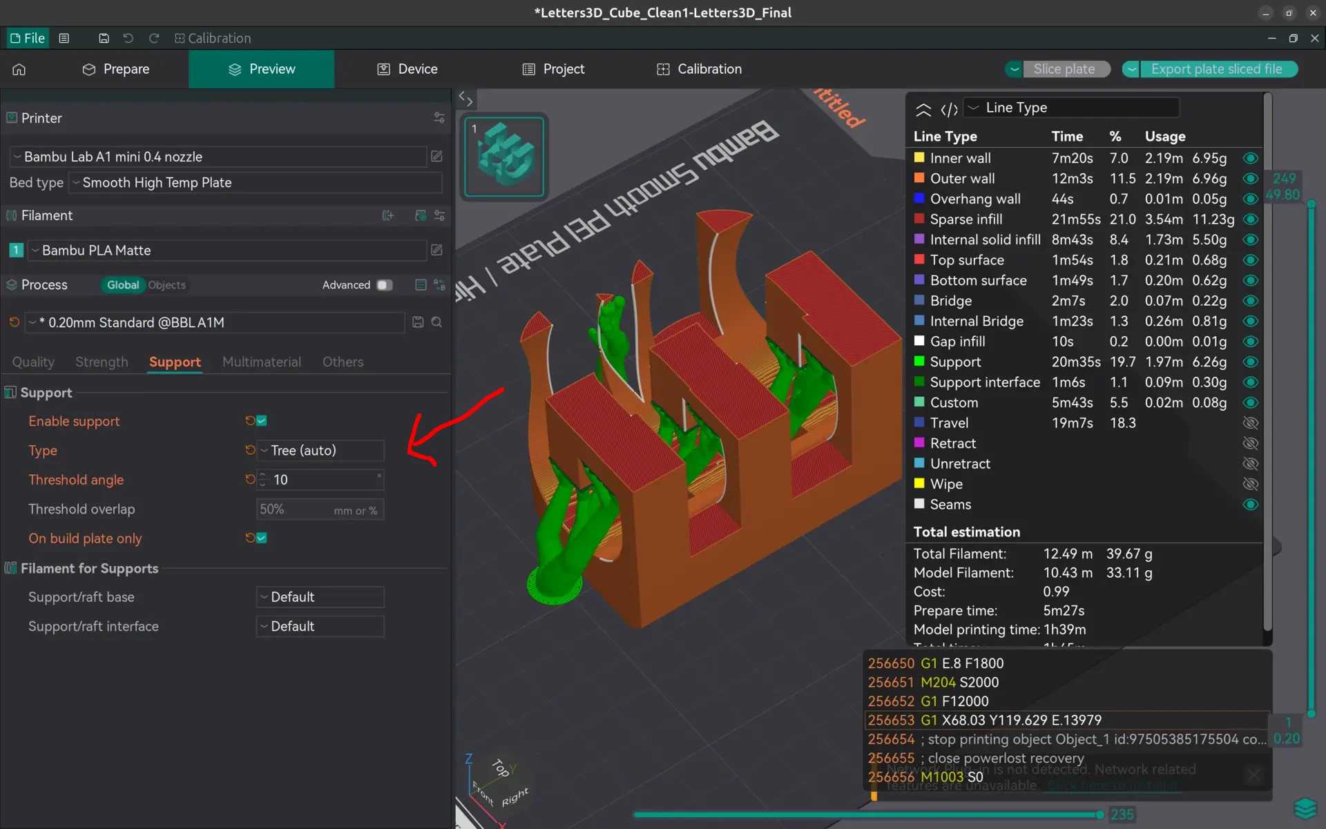
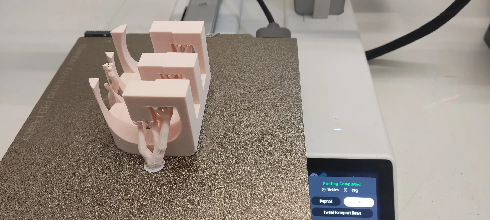
Here’s the final result, with supports:
And here’s the result without the support:
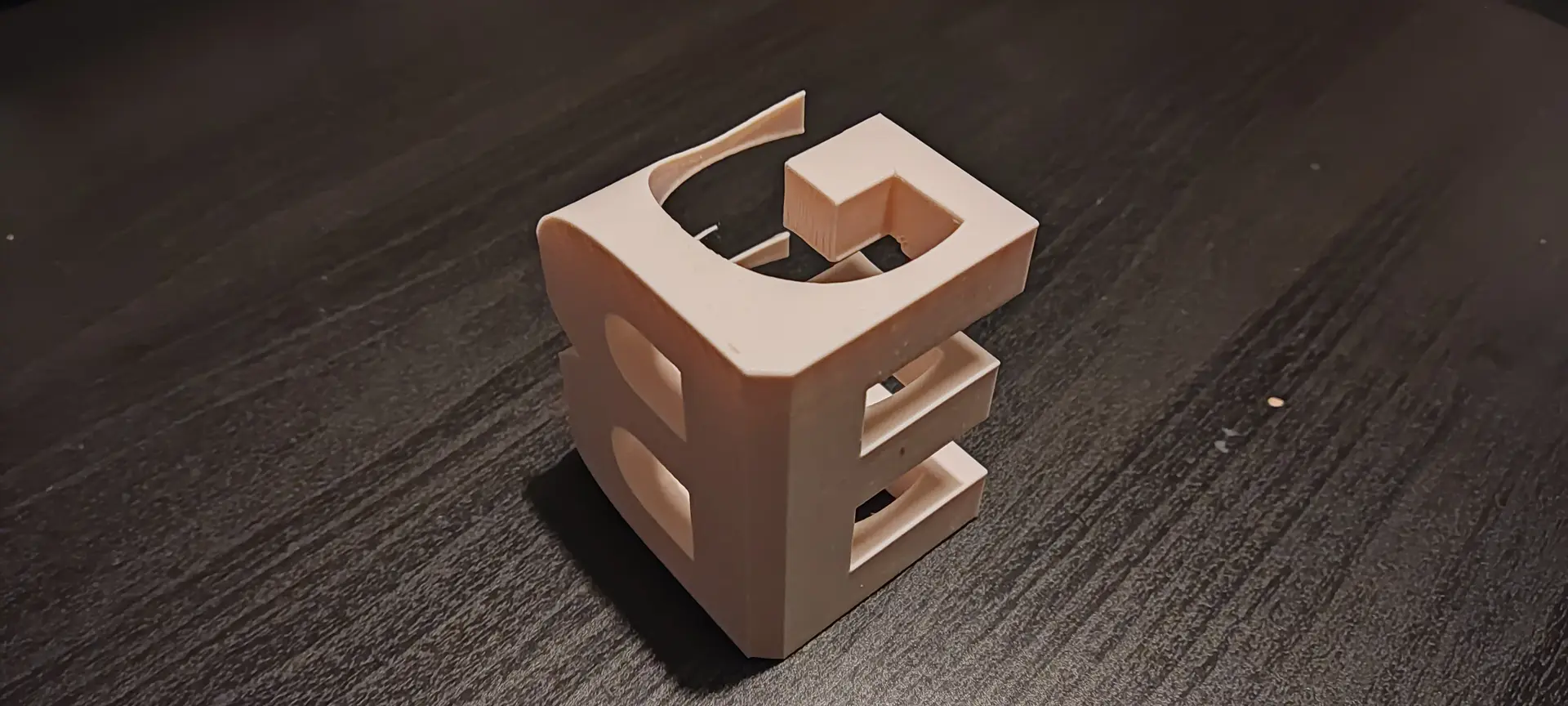
Although technically this could be done subtractively, the fact that the subtraction needs to happen in multiple orthogonal angles, makes it very difficult to do so without repositioning manually the piece in another angle and holding it appropriately.
I got featured in this week’s student review 🙌
Files
Checklist
- [x] Linked to the group assignment page
- [x] Explained what you learned from testing the 3D printers
- [x] Documented how you designed and 3D printed your object and explained why it could not be easily made subtractively
- [x] Documented how you scanned an object
- [x] Included your original design files for 3D printing
- [x] Included your hero shots