Individual assignment
Intro
After doing the class on networking week, and doing the board for the output week, I returned here to finish this assignment.
Here I describe the design of the board, but the production is documented in week 8. Also I’l just document the main steps of the design, since the generic detailed steps of designing a board is documented in week 6.
Since I already knew I wanted to use one board for communication, I designed a new one with I2C in mind. As for the input, since we used a digital rotary encoder in the group assignment, I decided to use an available analog potentiometer. I’ll also use a Xiao because it does not require the FTDI separate board or a programmer and is much more convenient.
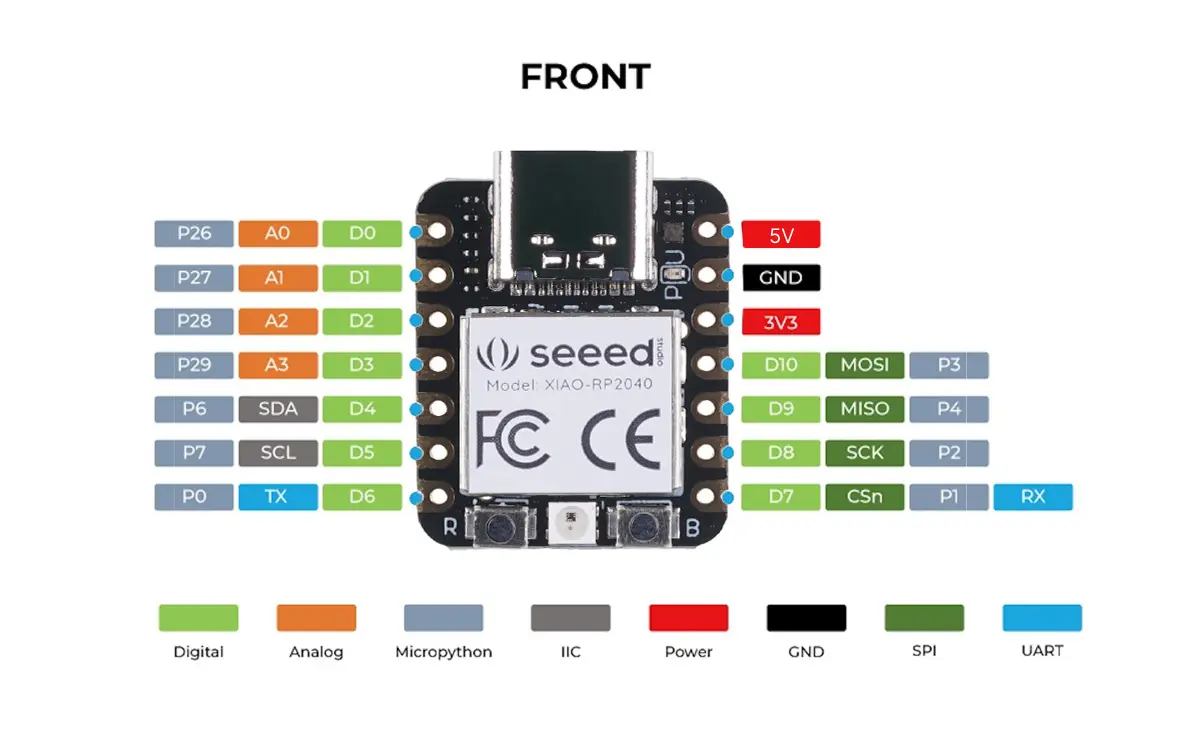
Here’s the main pins of the Xiao:
Testing the concept
Before we commit to making a permanent board I like to first test it out, to make sure I understand the components.
Since I didn’t have a datasheet for the potentiometer, I first test with the multimeter to assert what the resistance is and what the correct pins are:
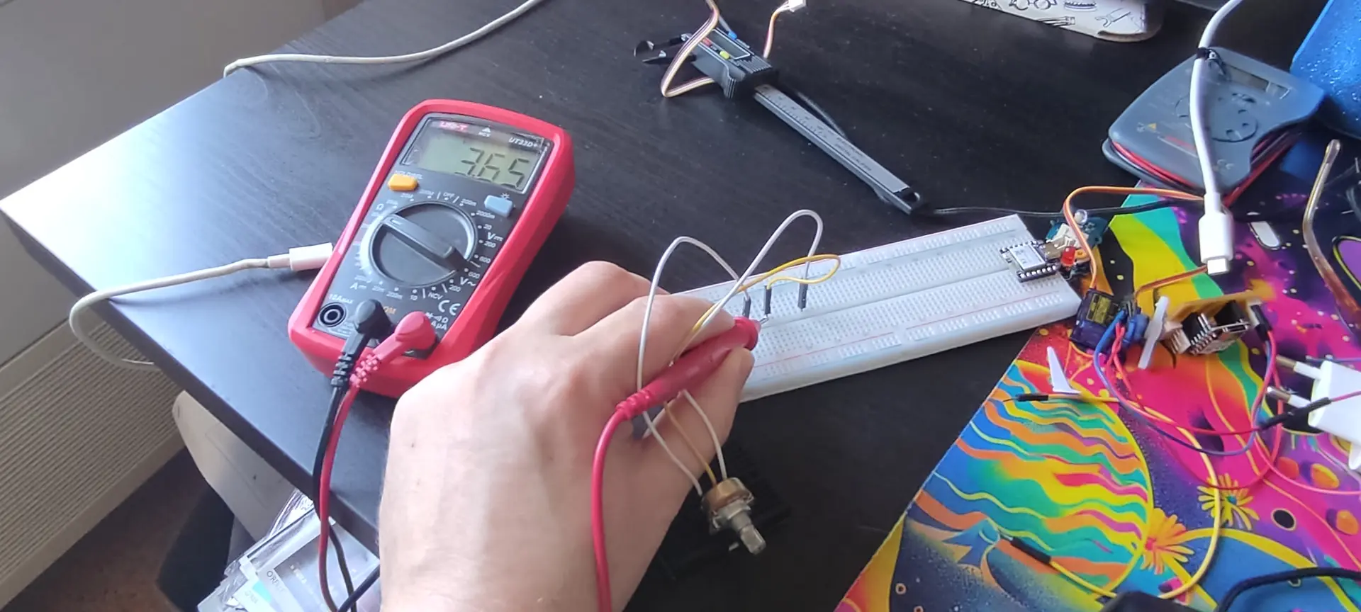
The potentiometer is 10 KΩ end to end and the middle pin is the signal one.
Then I connect the Xiao and test with the example AnalogReadSerial example sketch:
Once I understand that the resistance is adequate and I understand the correct pins, I proceed to design the board.
Potentiometer types
As pointed out by intructor Ricardo Marques, there are also logarithmic potentiometers where the response is logarithmic, rather than linear. The one I use, judging from the response, is of the linear kind.
Designing the board
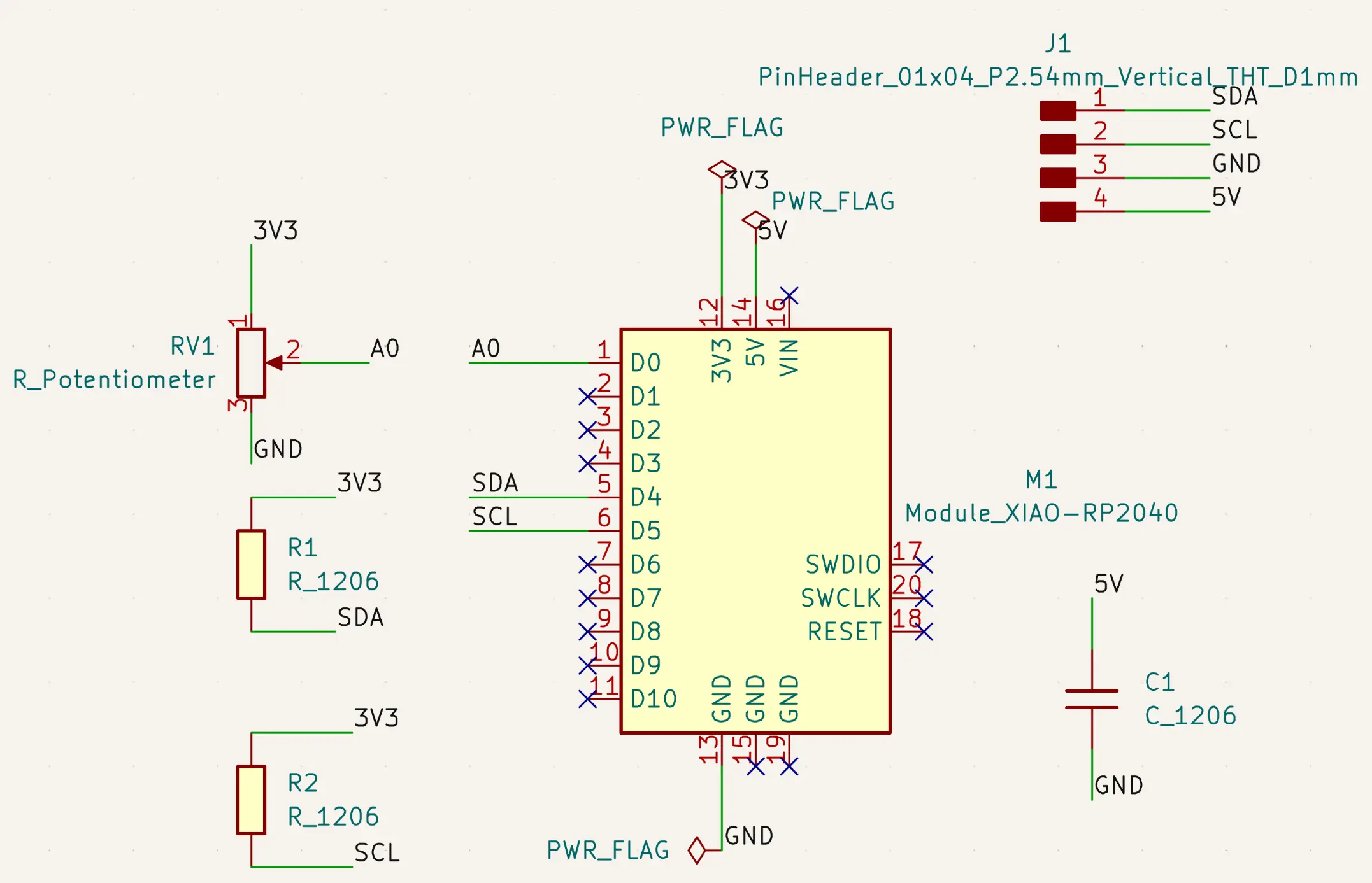
As mentioned, I already had the communication assignment in mind to use I2C, so I made connections for the I2C pins, namely the SDA and SCL, with pairing pull up resitors as recommended by the protocol.
I also included pins to share GND and 5V to have the possibility to share ground and possibly power another board.
So, Here’s what the schematic looks like, with all connections labeled:
The decoupling capacitor
I used the same 100 µF decoupling capacitor between 5V and GND that I used in my initial attempt at board design with the ATTiny412, but later, Ricardo noted that the Xiao already includes a decoupling capacitor. I checked the schematic, and a 10 µF is indeed already present. Since I added a larger 100 µF, the power should be even more stable, but the internal one is likely enough for most cases, making this redundant
Let’s move on to the PCB, and flip the through hole components, including the Xiao, because we want to plug it with female pins and through-hole pins are sturdier than SMD ones.
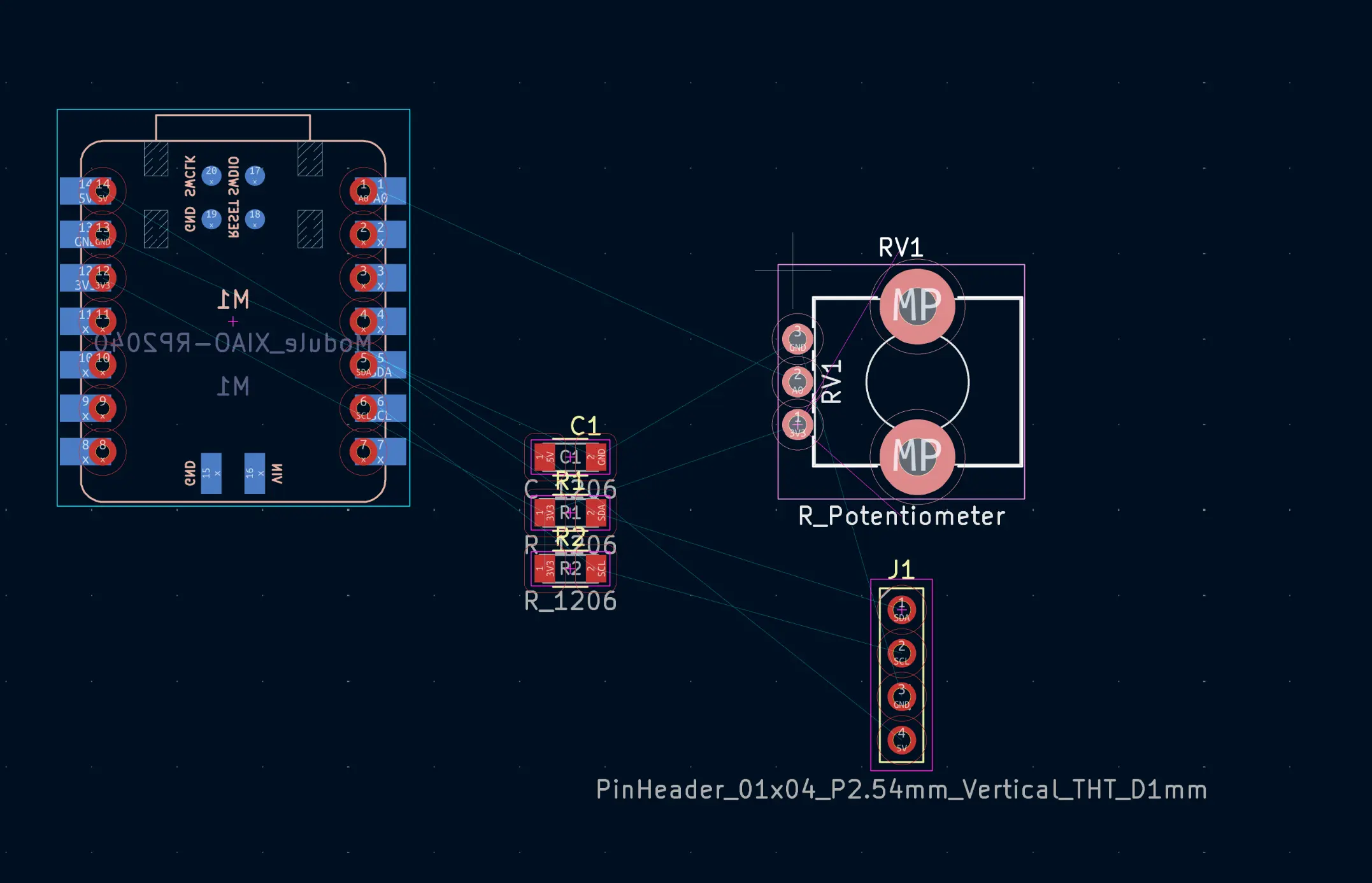
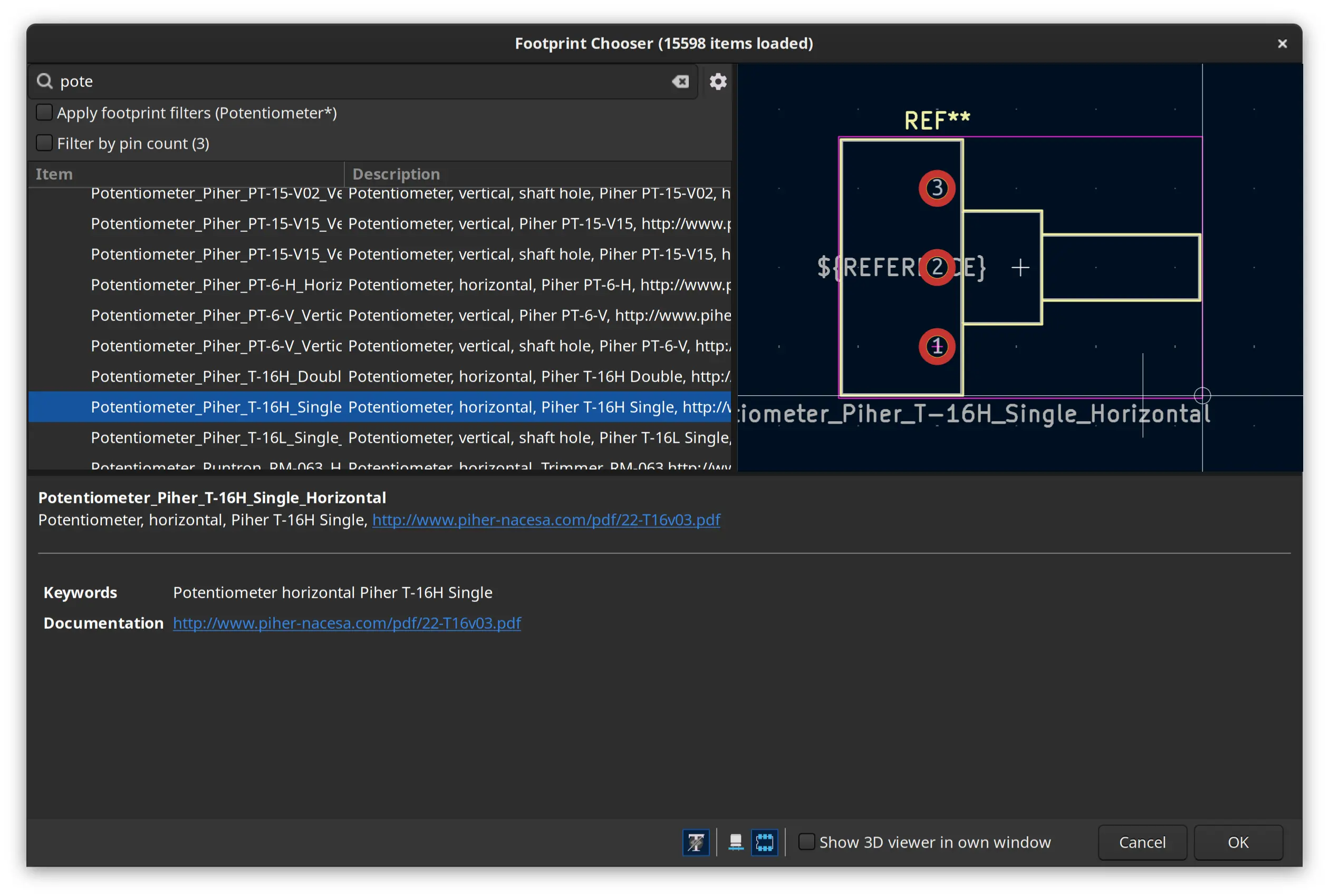
I notice that the footprint of the potentiometer does not match what I have, so let’s look for another. I right click and select “change footprint”
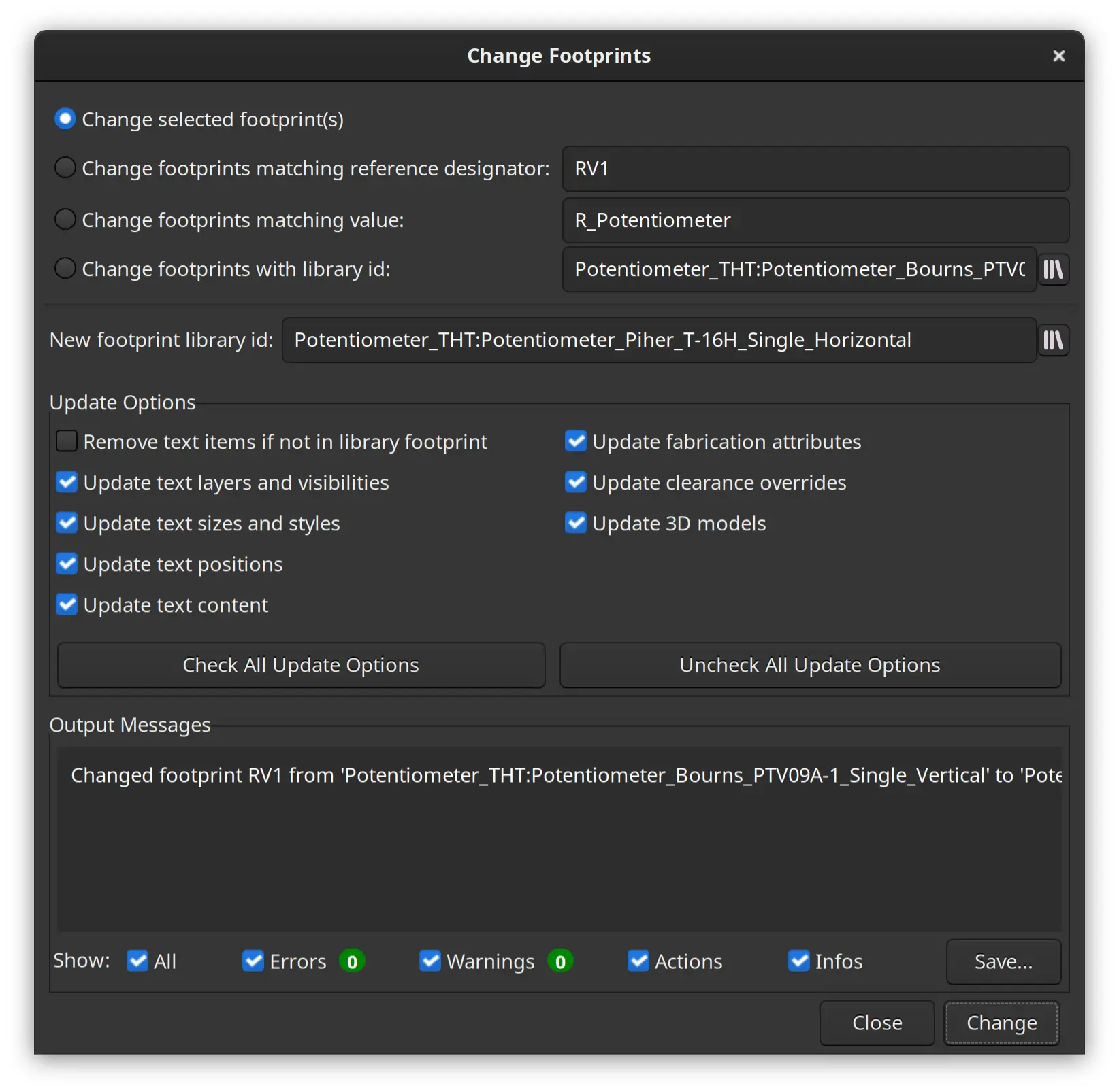
I browse through the available catalog and choose what seems to be the closest one:
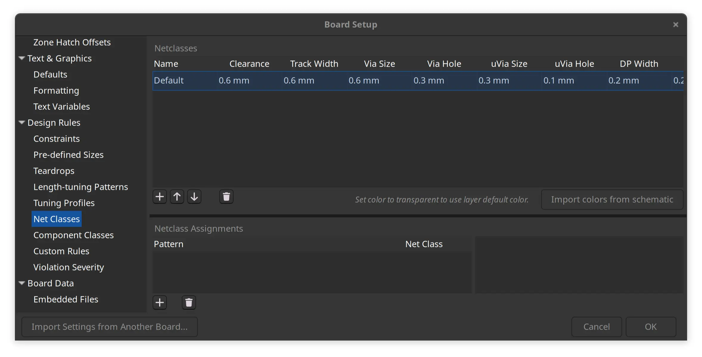
Before connecting the tracks, I went in to board setup and define track width and clearance as 0.6 mm
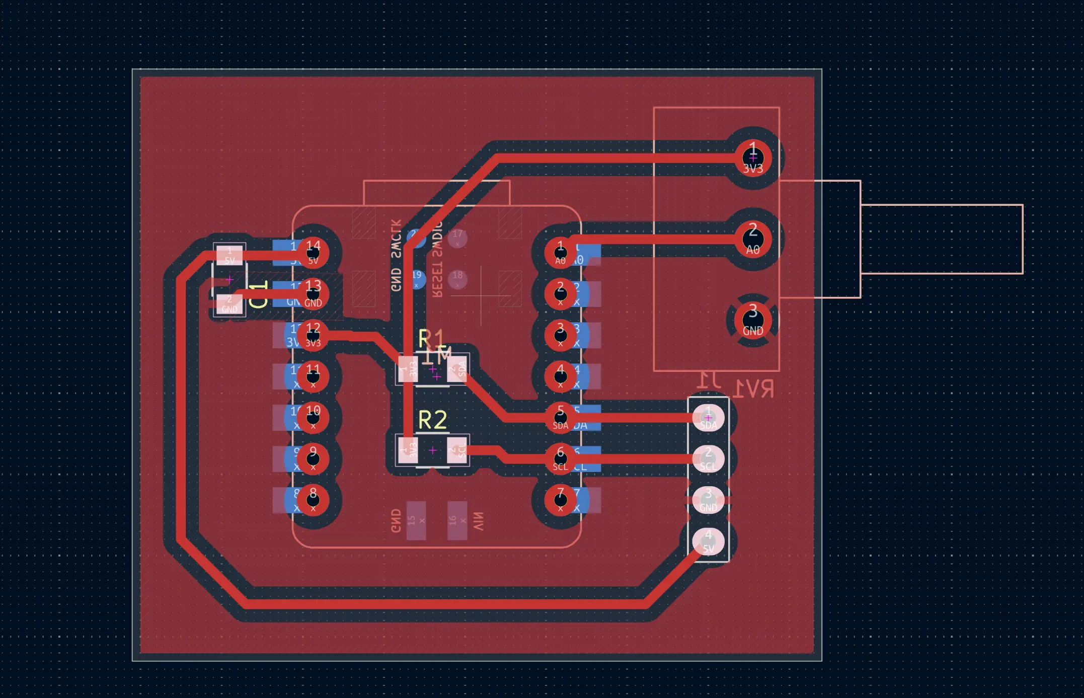
I connect the tracks, then select multiple pads and click the properties icon on the left:
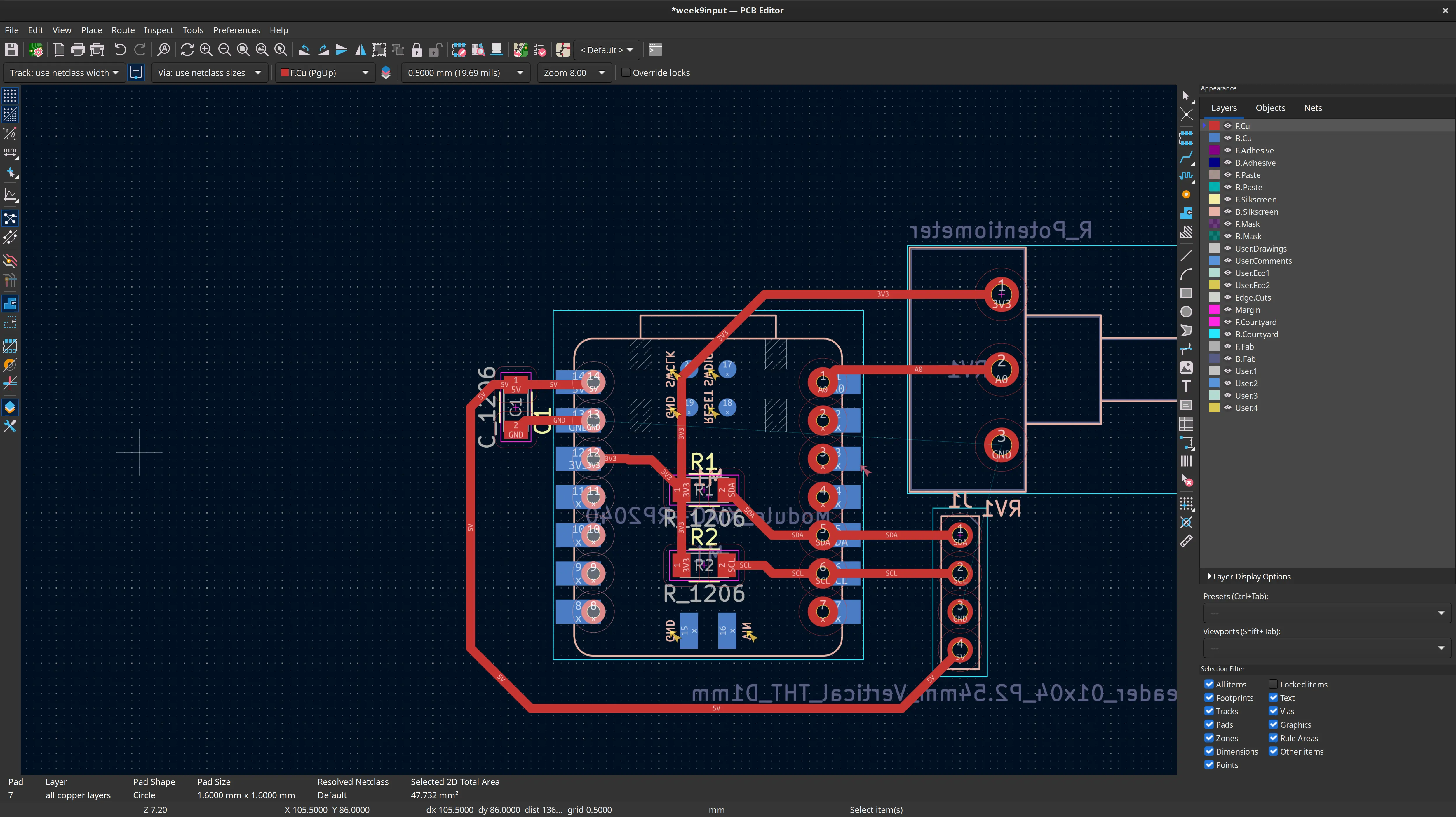
and change “Size X” to 2 mm to have bigger pads, since I know the smallest end mill cutter we have is 1 mm, and not the desired 0.8 mm.
Now it’s time to draw the limits of the board and the GND pour:
Producing the board
The details of the production of the board are in week 8.
Testing the board
I did a basic test of the board documented in the previous week, so let’s spice up little and make the analog readings also visible in the board itself, by controlling the NeoPixel:
#include <Adafruit_NeoPixel.h>

#define SAMPLES 50
#define PIN_NEOPIXEL_POWER 11   // Onboard NeoPixel power Pin
#define NUMPIXELS    1    // Just the one LED

// Initialize the NeoPixel object
Adafruit_NeoPixel pixels(NUMPIXELS, PIN_NEOPIXEL, NEO_GRB + NEO_KHZ800);

void setup() {

  // Requirement for some XIAO RP2040  neopixel versions: Power the internal rails
  pinMode(PIN_NEOPIXEL_POWER, OUTPUT);
  digitalWrite(PIN_NEOPIXEL_POWER, HIGH);
  pinMode(PIN_NEOPIXEL,OUTPUT);
  digitalWrite(PIN_NEOPIXEL, HIGH);

  pixels.begin();           // Start the NeoPixel
  pixels.setBrightness(30); // 0-255 range (30 is plenty for a desk)
  pixels.show();            // Initialize all pixels to 'off'
}

void loop() {
  float averageValue = 0;

  // Smoothing loop
  for (int i = 0; i < SAMPLES; i++) {
    averageValue += (float) analogRead(A0) / SAMPLES;
    delay(1);
  }
  Serial.println((int) averageValue);

  // Threshold logic
  if (averageValue <= 340) {
    // Set color to RED (Red=255, Green=0, Blue=0)
    pixels.setPixelColor(0, pixels.Color(255, 0, 0));
  }
  else if (averageValue >= 680){
    // Set color to GREEN (Red=0, Green=255, Blue=0)
    pixels.setPixelColor(0, pixels.Color(0, 255, 0));
  } else {
    // Set color to Yellow. Making green 255 would make it closer to white
    pixels.setPixelColor(0, pixels.Color(255, 130, 0));

  }

  pixels.show(); // Push the color to the hardware
  delay(30);
}
The values are read and averaged to smooth a bit some oscillations, and then the 1024 range is roughly divided into 3 parts, outputting red, green and yellow in each bracket respectively.
Here’s the result:
We can see that, as I turn the dial, the color moves from red to yellow to green as intended.
Dealing with oscillations
Ricardo pointed that we could also have smoothed the oscillations by adding a capacitor between signal and GND, although this could make the response a bit slower. In this case I prefer to do the smoothing by software as one can always easily change the response handling whereas with the capacitor, one would have to desolder and solder a new one.