Individual assignment
Intro
As Neil mentioned in class, molding and casting is one of the most underrated parts of Fab Academy.
I liked the molding and casting week where I did the master mold in the CNC machine, which I filled with a silicon based liquid to finally produce the tiles I wanted.
For this week I wanted to do molding again, but with different technique and materials.
So, I’m making molds in the resin printer, and and using injection molding with recycled plastic.
Also,the mold will more complex than before.
The equipment
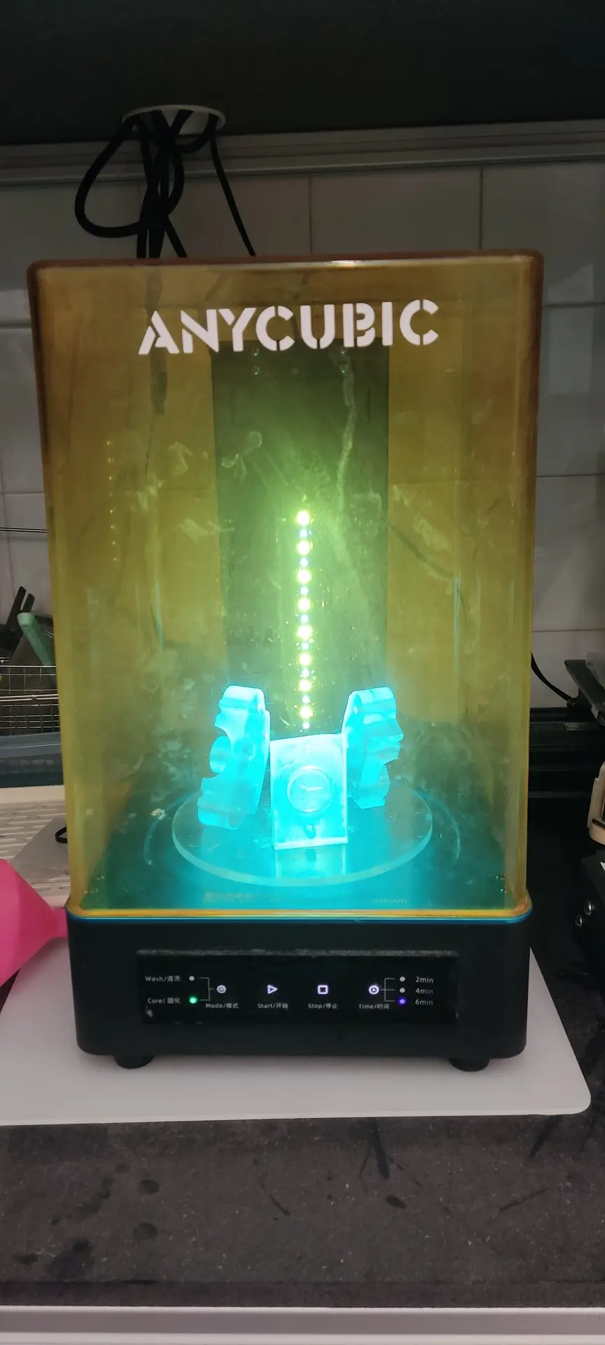
For making the mold, we have the UniFormation GK Two resin printer and the Anycubic water-wash Clear Resin
We have a manual shredder that I use for shredding HDPE plastic scraps that we have at the lab.
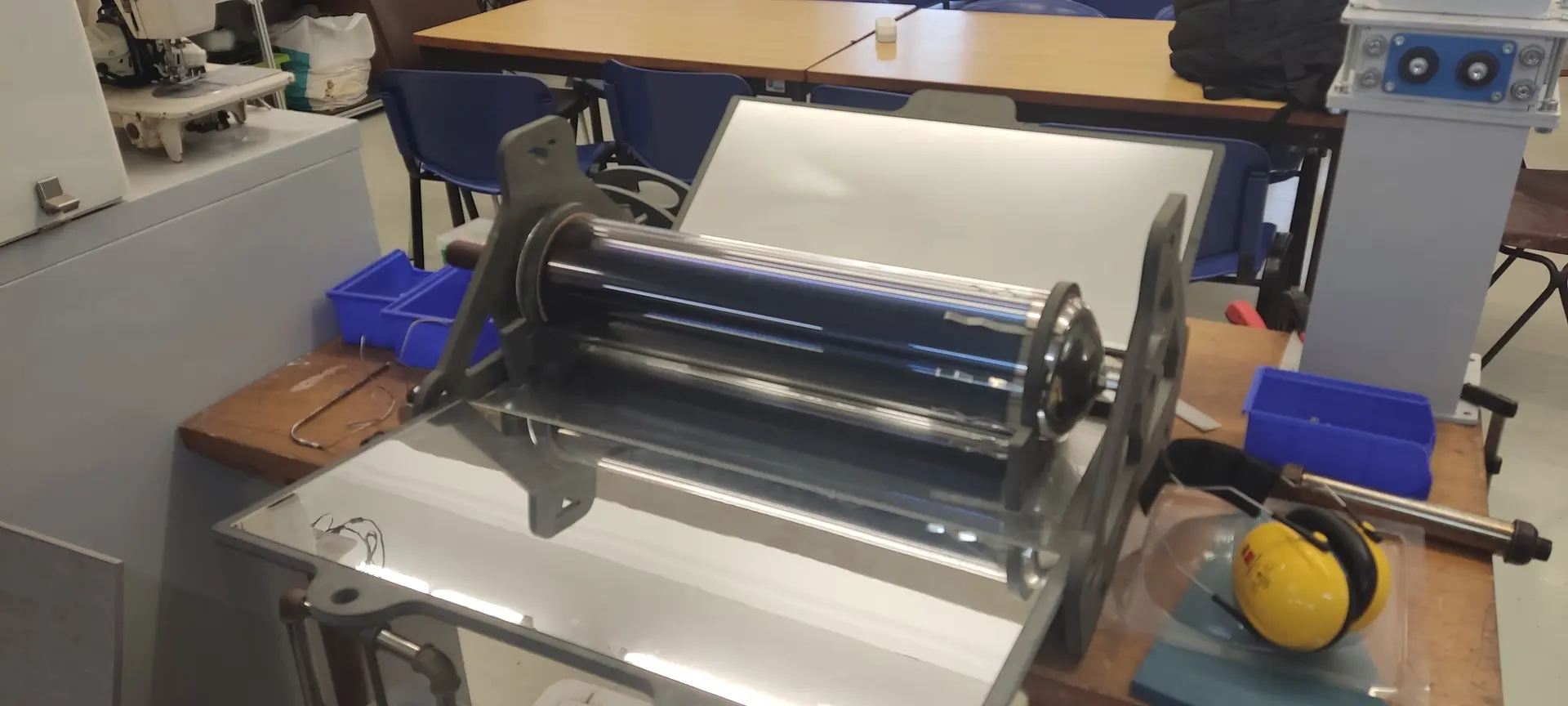
For melting and injecting we have at the lab a portable solar plastic recycling kit.
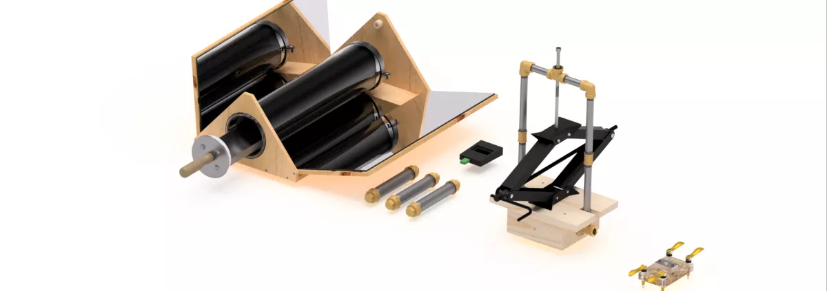
Note: plans are available to build and operate that kit.
The theme
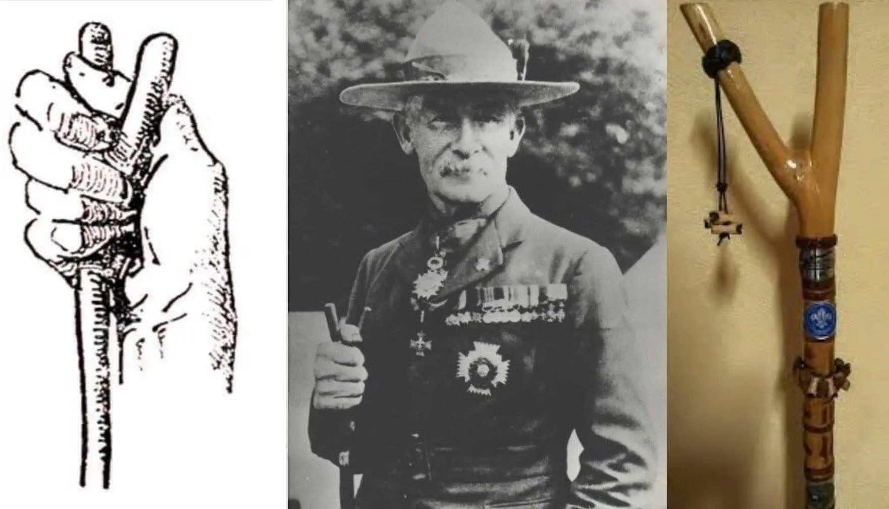
Since I’d be doing some recycling which is good for the environment, and is something is promoted in Scouting, I thought about doing a woggle, with a staff relief which is one of the symbols of the Rover Scouts.
The Thumbstick: This is a Y-shaped staff used by Rovers as personal support. The two uneven branches symbolize the alternatives or choices a young adult must consider in life, with the long branch representing the straight path and the short one cautioning against shortcuts
The design
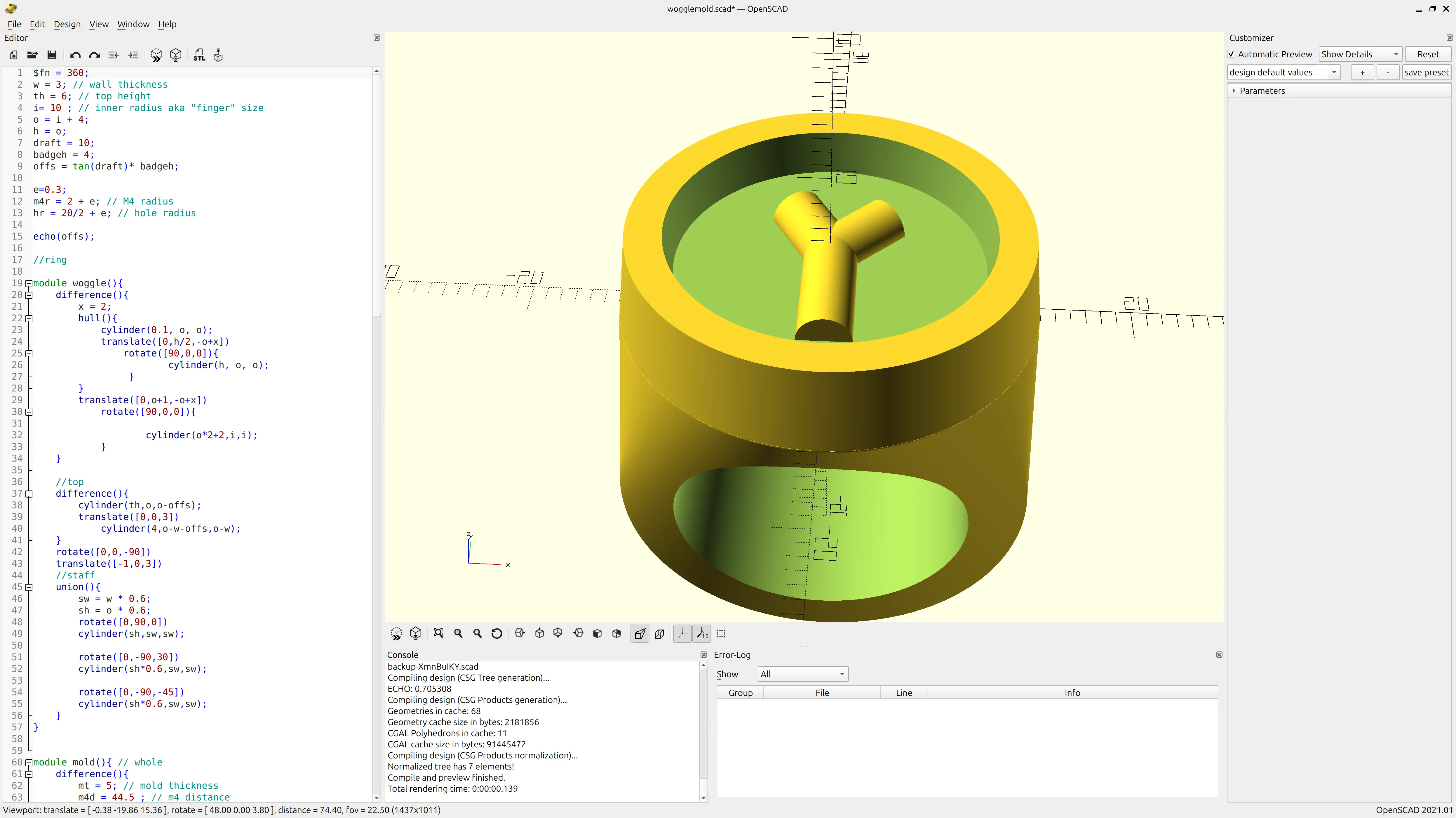
I’ve been a developer for a long time, and like the “X as code” approach, including for CAD, so I used OpenSCAD for this.
The woggle
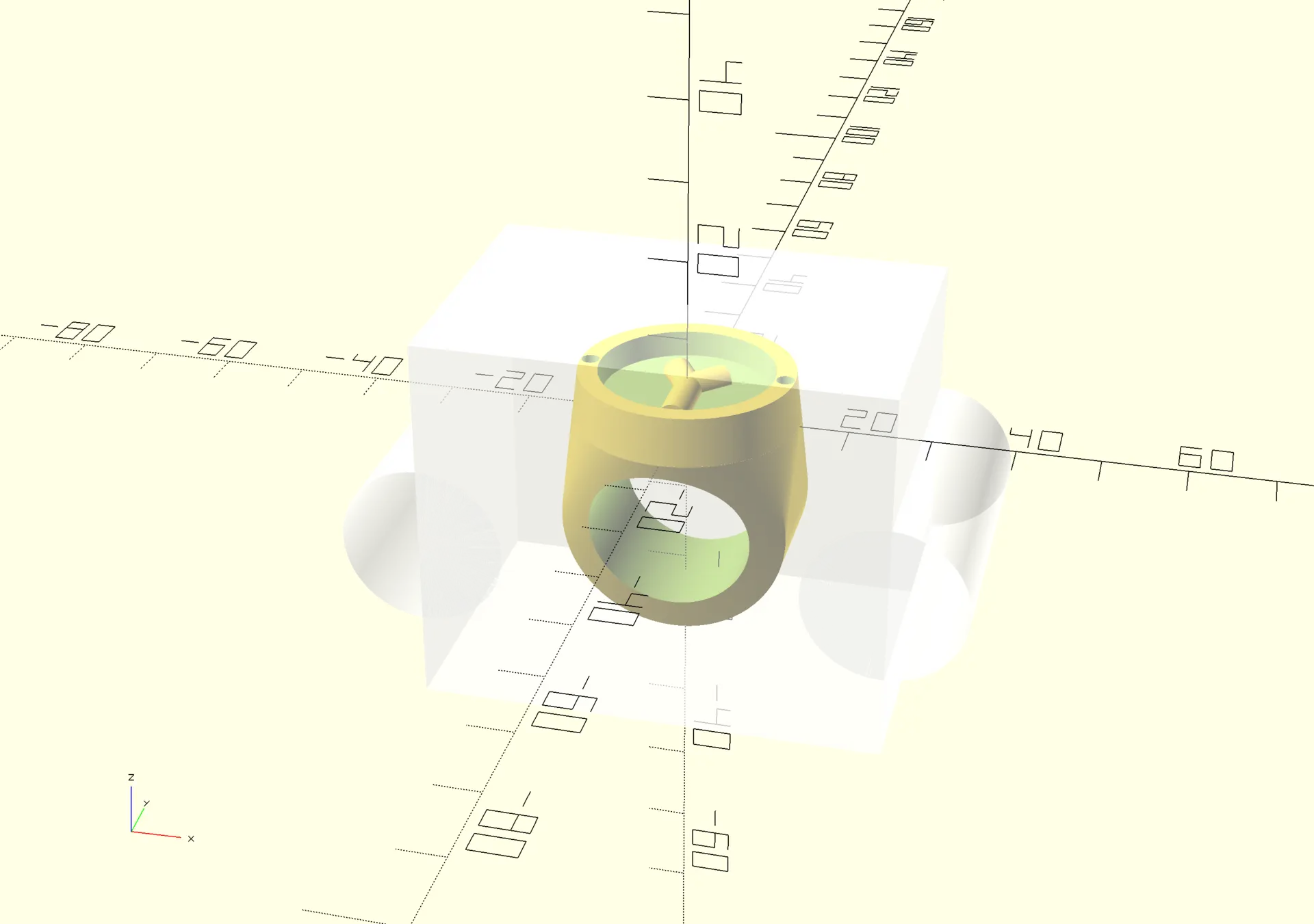
I designed the the whole woggle parametrically so I could experiment changing some sizes to get a feel for the right proportions.
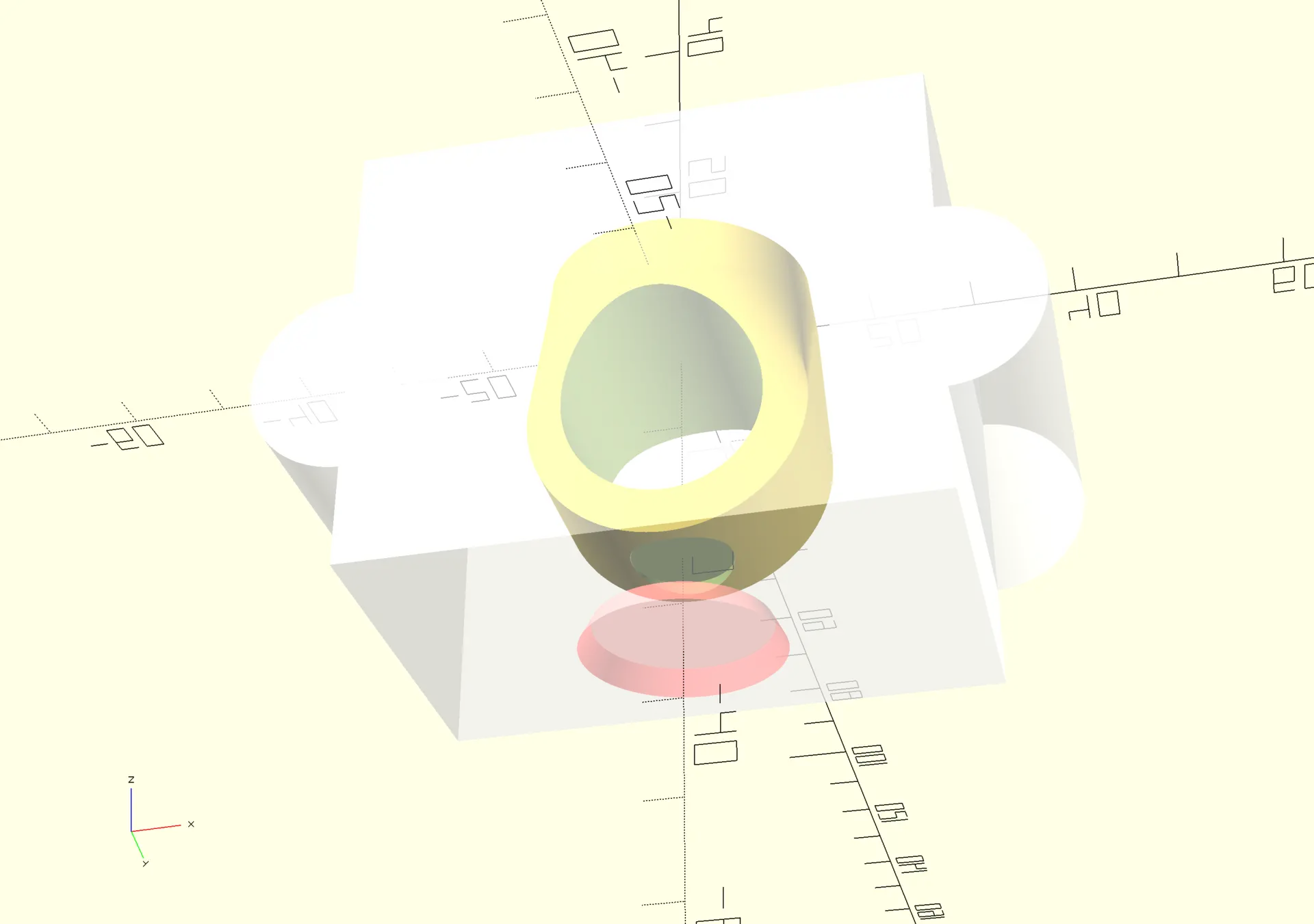
The main body is comprised off a hull between a cylinder and a flat disk, with a removed cylinder to make the main shape. Then I add a top with 10º draft for easy mold removal, and finally 3 different cylinders at different lengths and angles make the the staff shape.
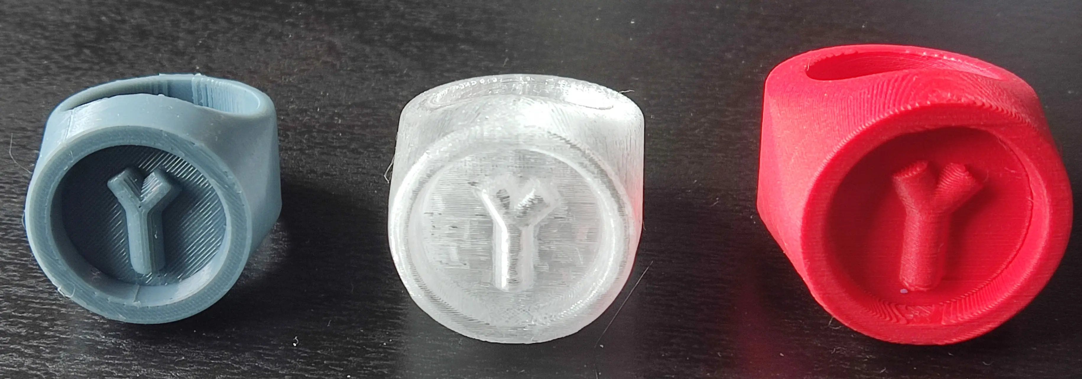
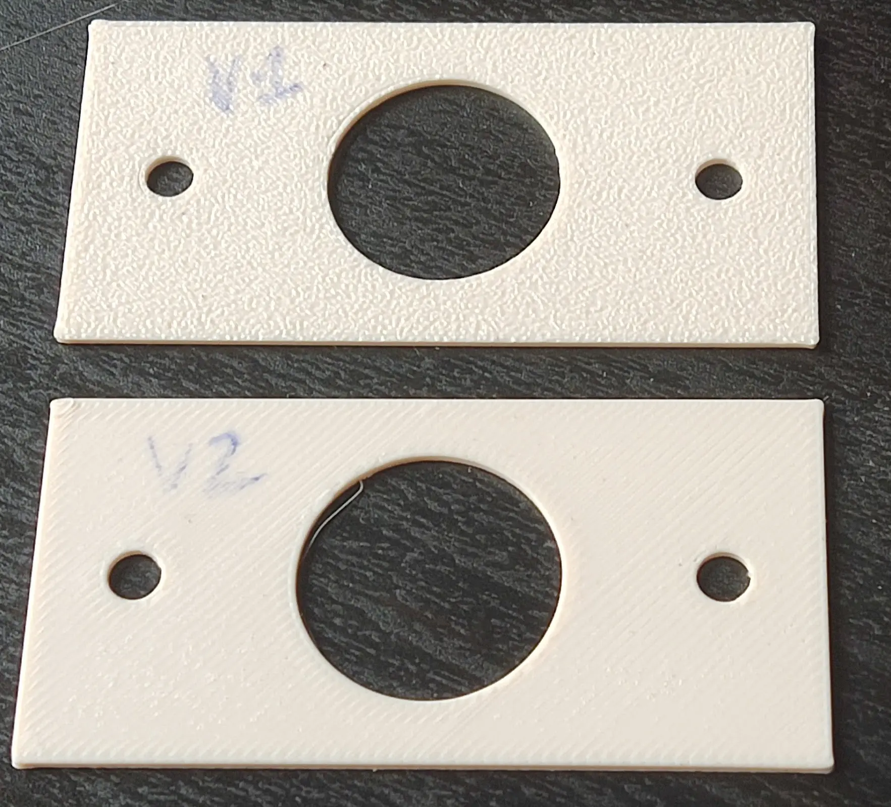
I 3D printed a few iterations with different proportions, before I finally settled on final dimesions:
The mold
While the the woggle was done parametrically for experimenting with different sizes, the mold part was mainly half eye balled to be a good fit and would have to be adjusted for a very different size. This made it quicker to deal with hard numbers rather than formulas.
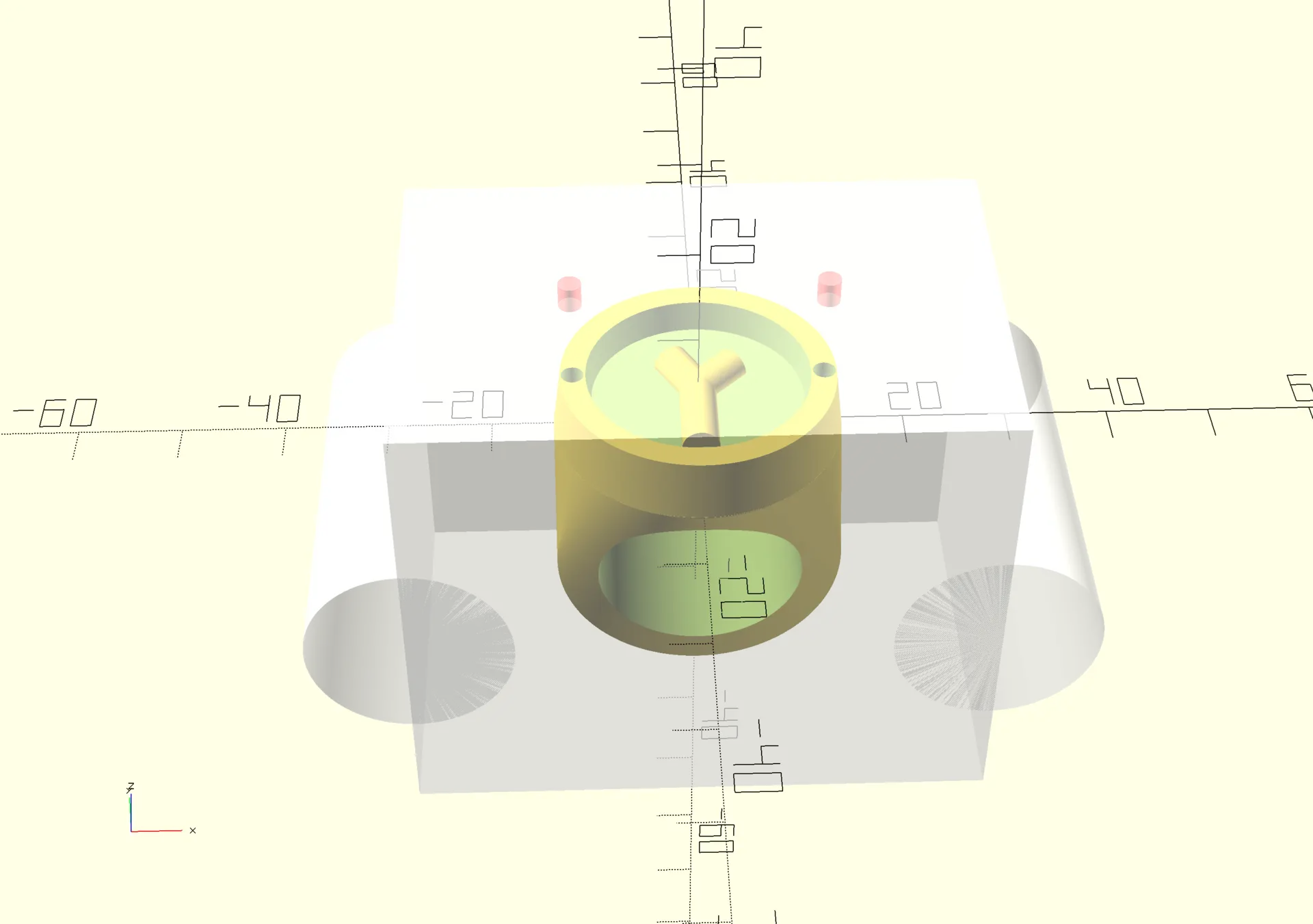
This is basically a cube, with some ears for bolt fittings.
Fitting for the bolts
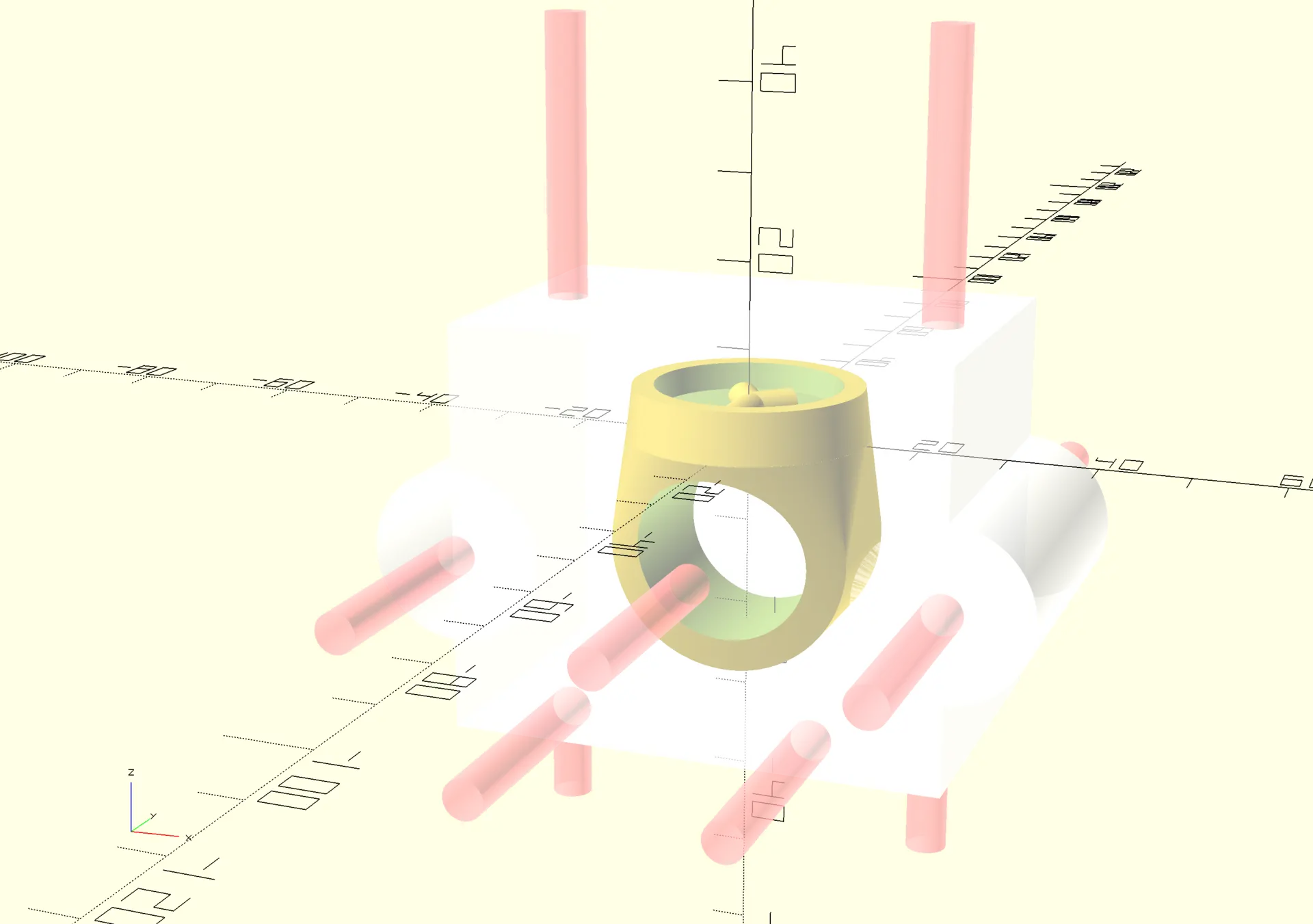
Before splitting the mold in parts, I subtract the fittings for tightening bolts.
Unfortunately I made it all M4 size, but only the vertical ones were supposed to be of size M4, and the other ones were supposed to be of size M6, so they could be quickly tightened with some bicycle tighteners that were part of the kit.
These were the M6 tighteners I was supposed to use:
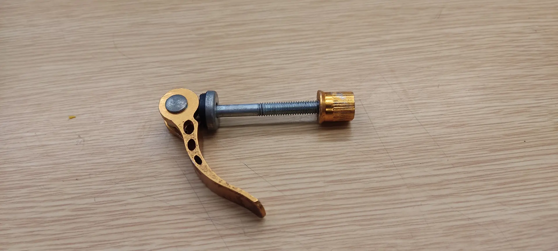
Oh well, M4 regular bolts will have to do 🤷♂
The vertical bolts have to fit a precise kit piece for connecting the molten plastic container to the mold.
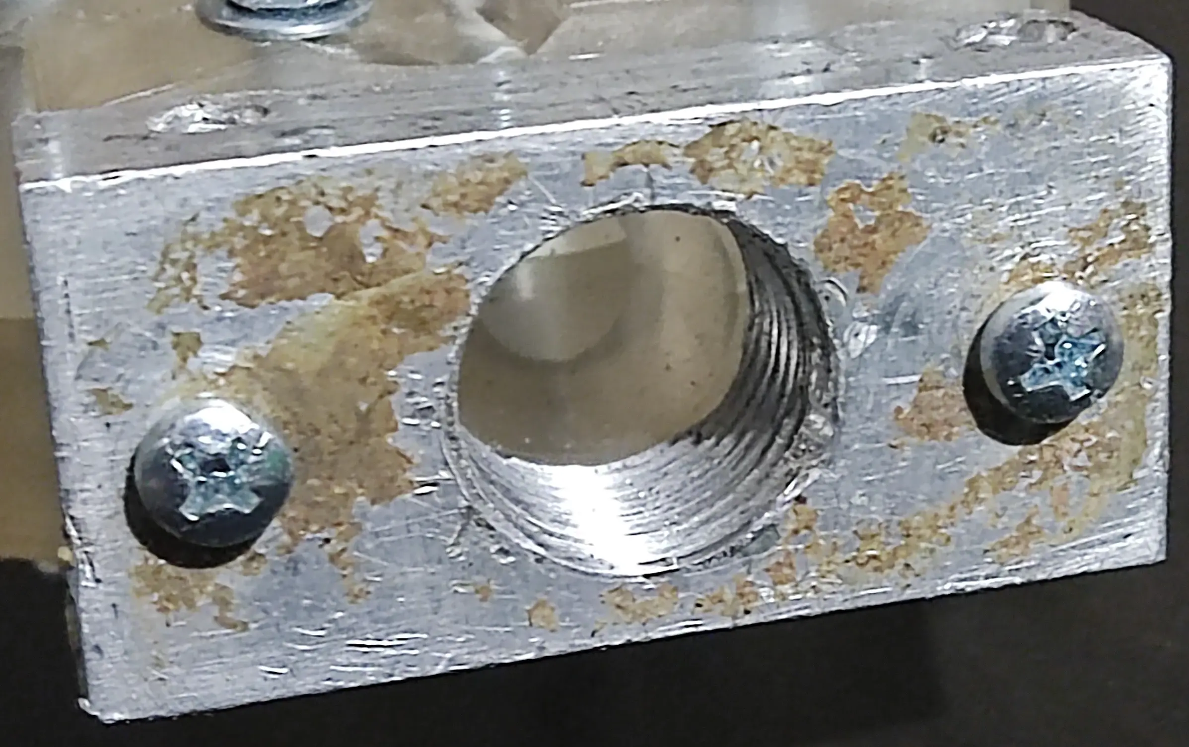
I measured it with a caliper, but just in case, I 3D printed a 1 mm rendition of the the piece surface, so that I could test and assert the measurements were indeed correct. The distance was perfect, but I increased the hole size, because making it exactly 4 mm, made it difficult to insert the bolts.
Plastic entrance and air vents
Next I make a cone shaped entrance for the plastic:
And I design the air vents:
There needs to be an air vent on the opposite side, otherwise the pressure when injecting would be to much and could break the mold. More on that later 😬
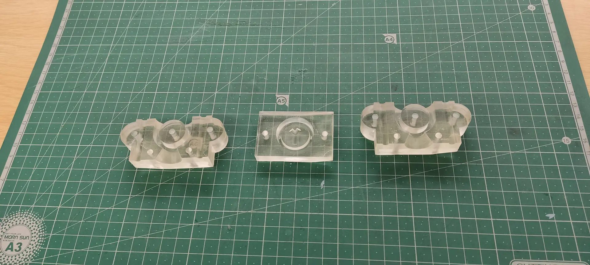
3 way split
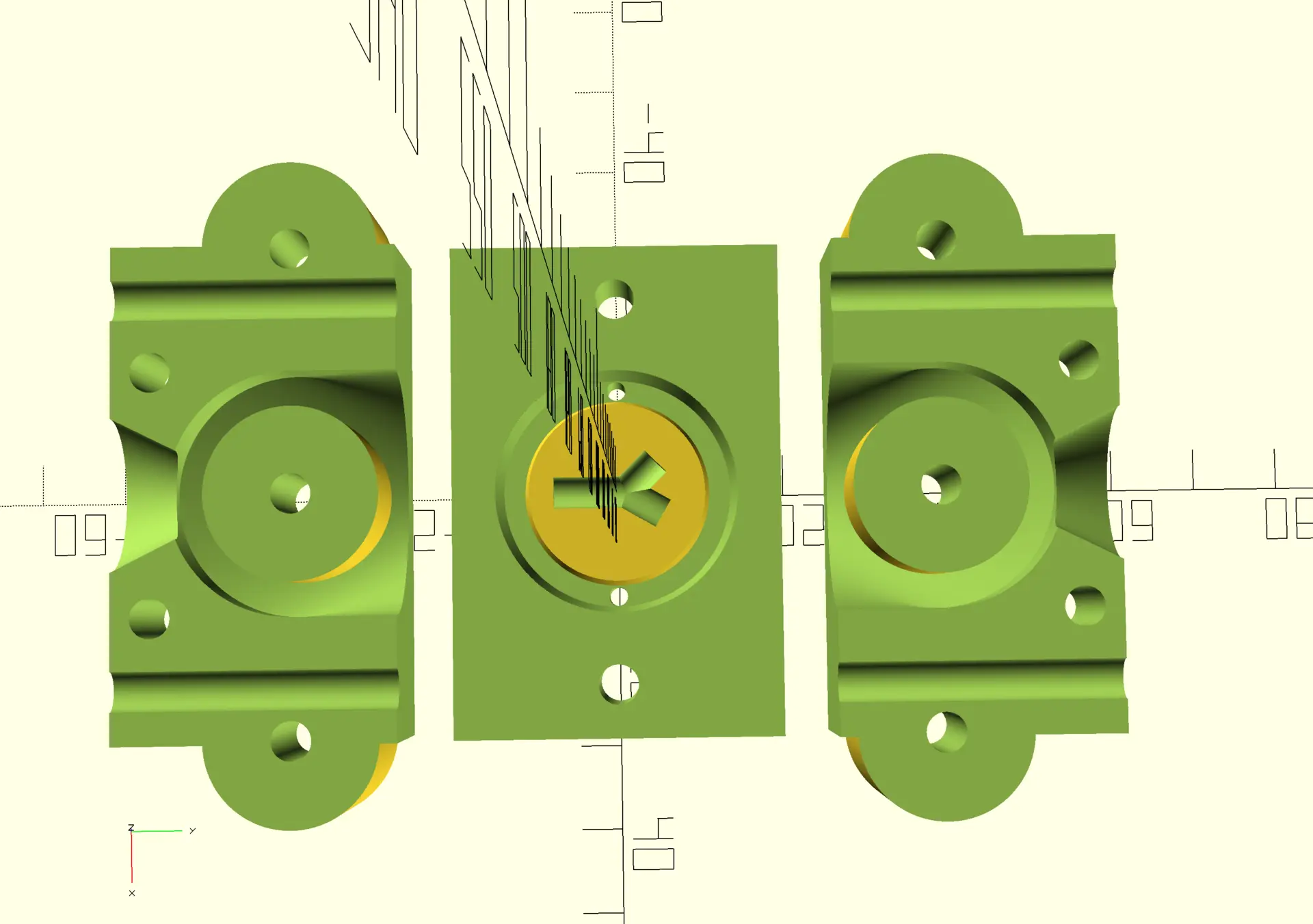
Next, I need to split the mold in 3 parts so that no part of the shape get’s trapped inside the mold.
I split it, and lay it out on a plane, so that all the pieces could be printed at once:
Resin printing
The Orca Slicer that usually use for the FDM printers had no support for our lab’s resin printer, so, when teaching me how to use it for another print, instructor André Rocha said I should use Chitubox, for which he already had a configuration to use with our resin. I complied, but had to use the lab’s PC to install the windows version, since the latest version does not support Linux.
For this project however, I found out that I could still download the previous basic version, which was available for Linux, and neither required internet nor login, and that’s what I used.
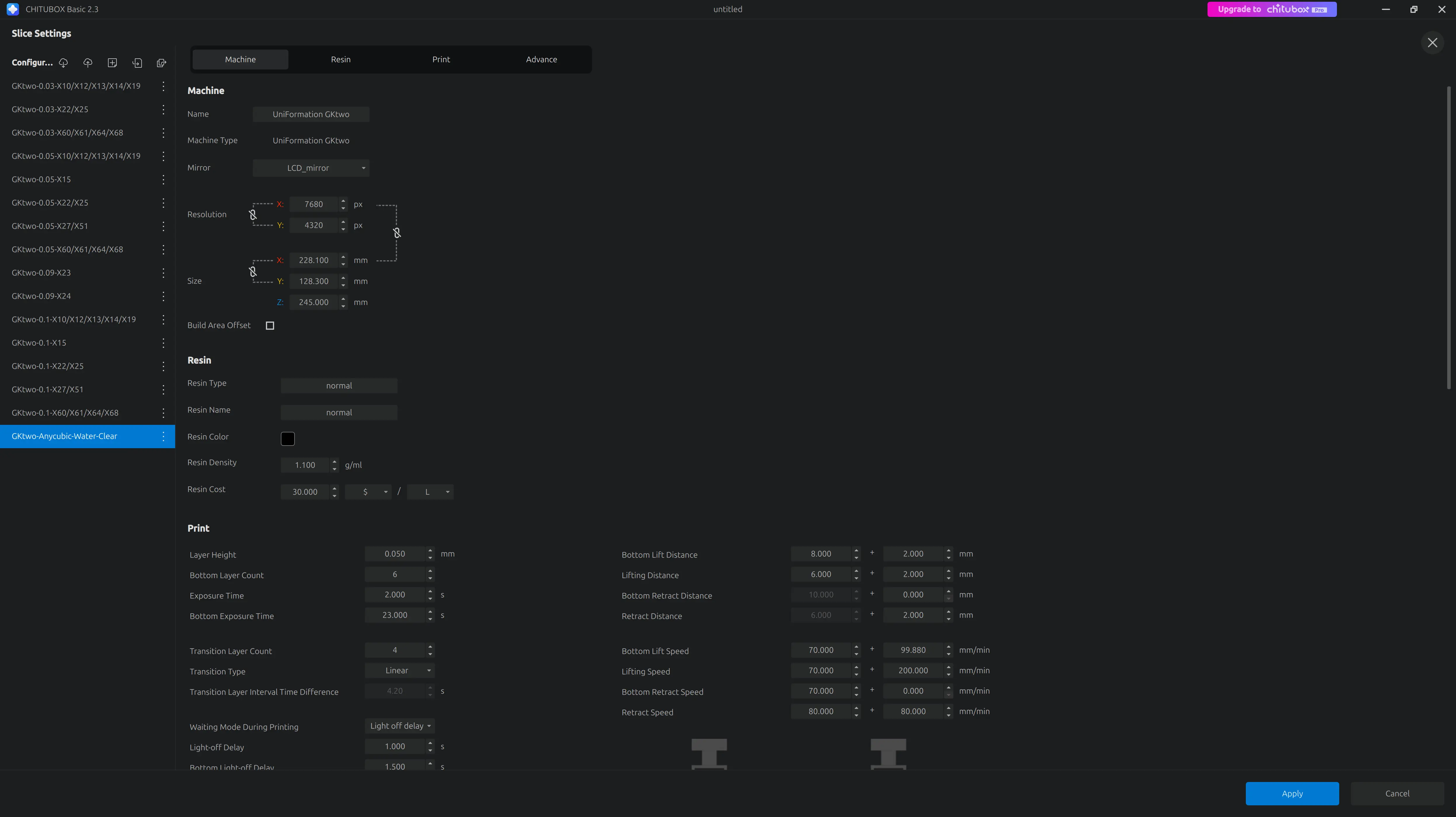
Settings
I imported the configuration for he printer/resin combo that André provided:
Placement
While learning to work with the software, André explained that the pieces need to be printed tilted, but I didn’t quite understand the implications of not doing so.
I tilted the model manually, given the basic version doesn’t seem to do that automatically, but that would have amounted to over 10h printing time, and I didn’t really want to spend that much time waiting, so I risked it and printed it flat after adding the raft and some supports.
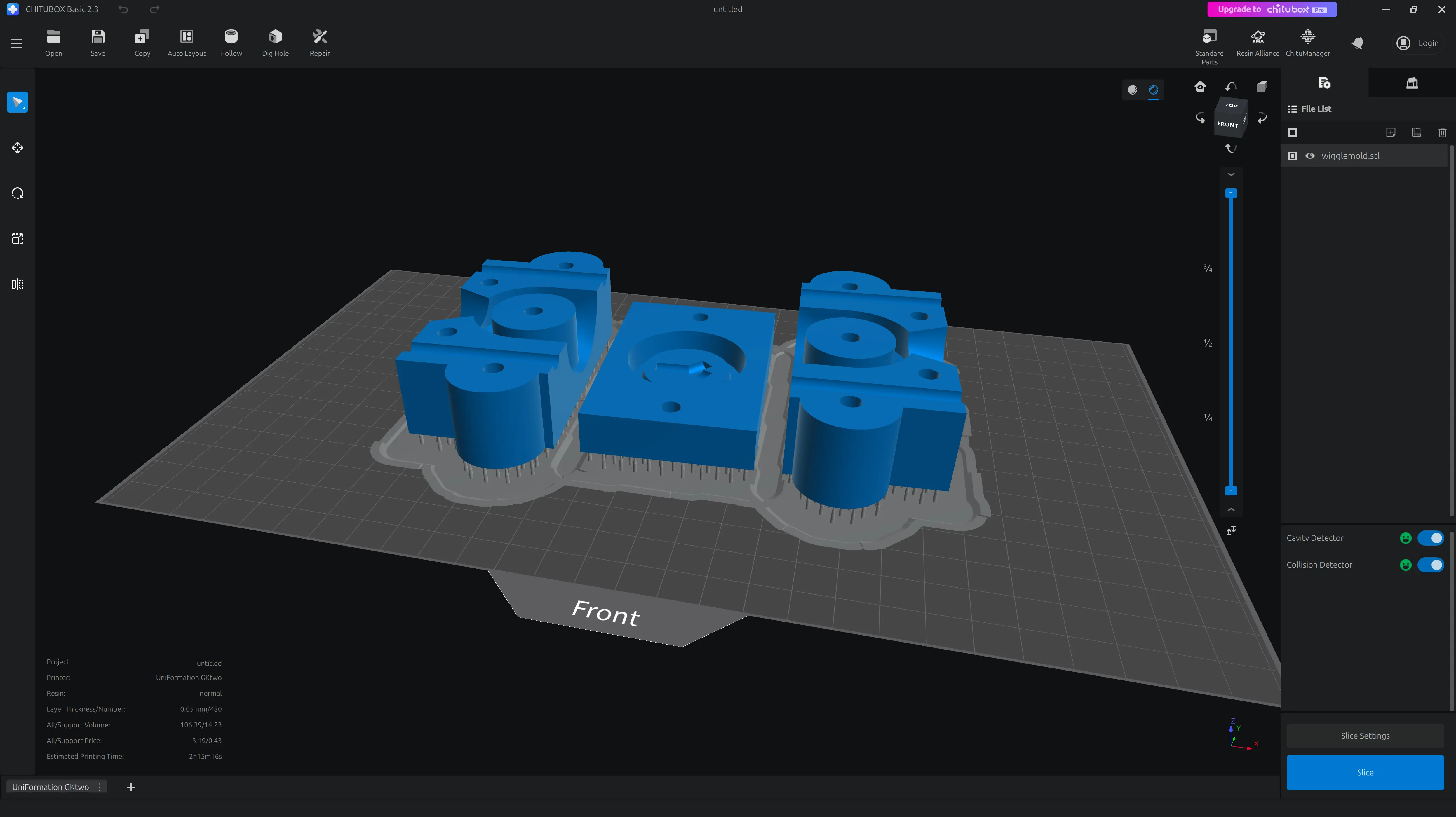
Only later did I read more about “peel force” and “suction effect” 😅
Mold results and post processing
The print right out of the printer.
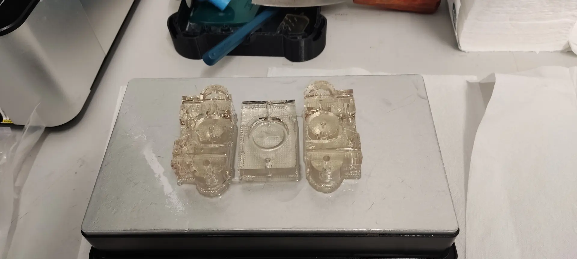
After washed and cleaned with water :
And now for some UV curing, which I set around 20 mn total.
They came out a bit yellowish, so I could have done less time, I guess.
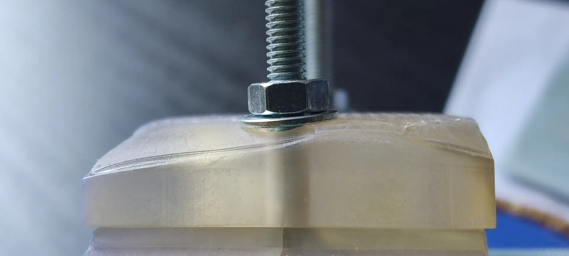
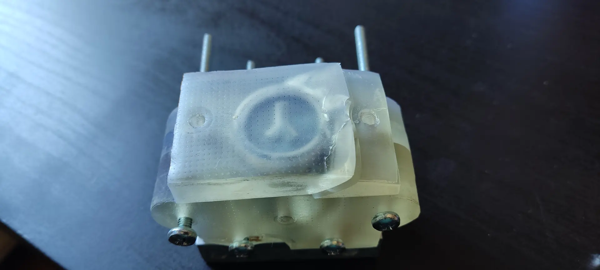
I then attach all the parts, with bolts and nuts, and this is what it looks like:
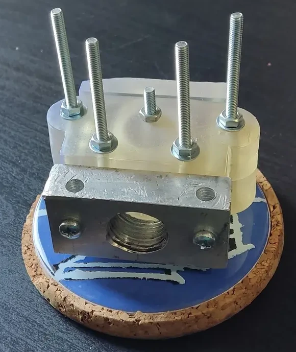
When assembling, I notice that some corners of the top mold are not perfect, likely due to the lack of tilting when printing. I guess I now see the effects of the lack of proper tilting! 😬
This means the pressure on the washer is not even, but hopefully this won’t be much of a problem.
Melting plastic and injection
Preparing the plastic
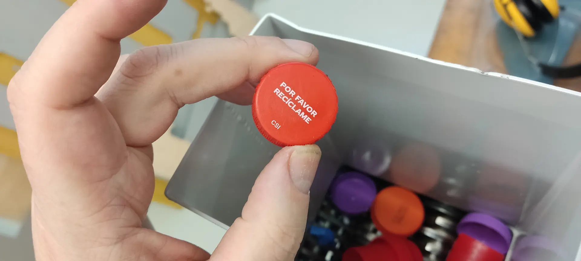
I picked some material from the HTPE scrap box :
And grinded it. The grinder is manual and it’s more work than it seems 😅 Also, multiple passes are required to get finer pieces.:
Melting the plastic
I place the plastic bits inside the metal container:
And place it inside the solar oven and leave it outside while I go for lunch.
Extruding the plastic
When I return, I remove the container from solar oven with the help of some oven mittens (it’s very hot!), and attach it to the end of the scissor jack, attach the mold to the container, and crank the jack until the plastic visibly comes out inside the mold.
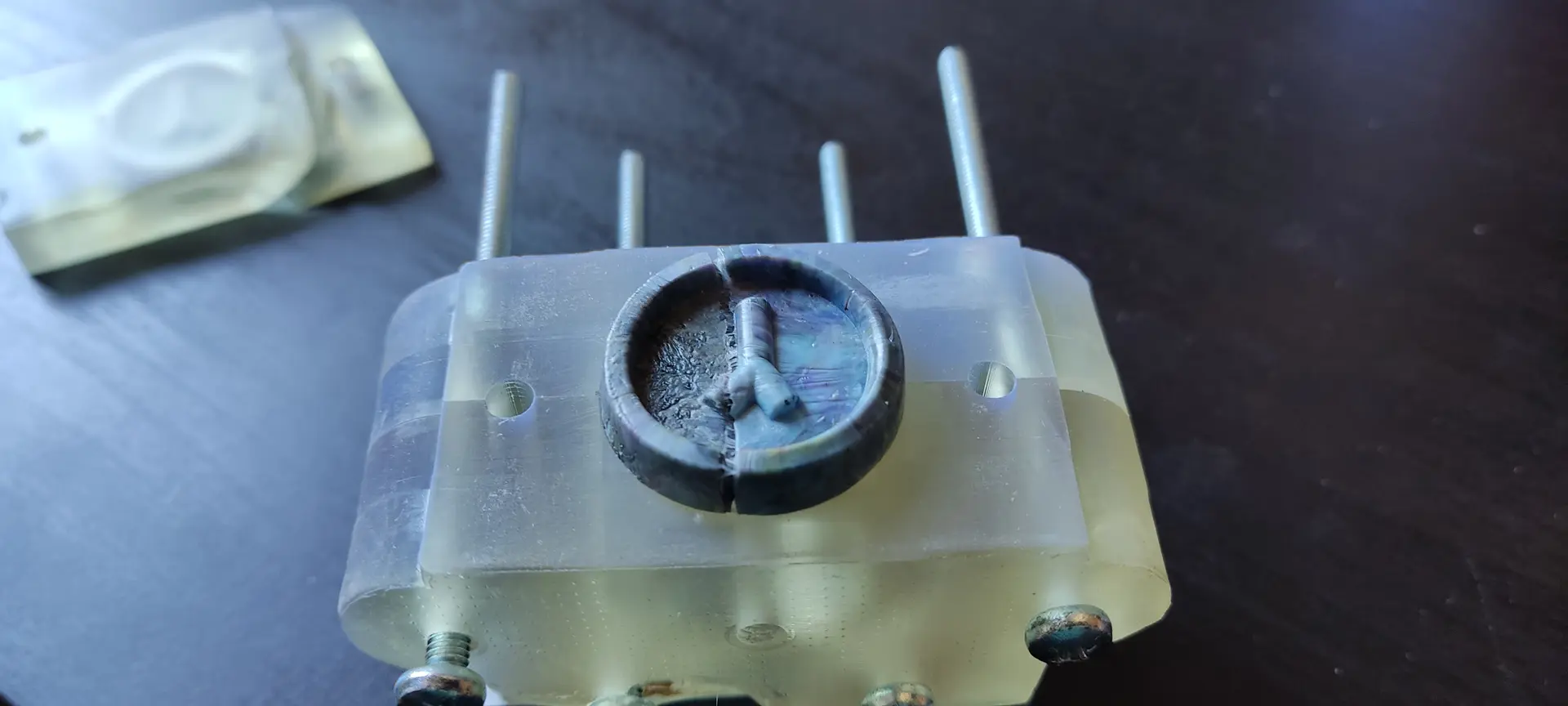
Sadly, I cracked the top mold in this process. 😢
I thought this was due to this part’s imperfection mentioned earlier, but on the post-mortem inspection, I think this was a minor contribution. The top mold was also not as thick as the side molds, and I think the main culprit was too much pressure inside due to the air vents not working.
When I inspected closely I noticed that the air vents might have been too narrow, and while printing, the hole didn’t actually open all the way through.
I suspect I cannot have holes that are too narrow on a resin print, because due to surface tension, the resin might get trapped, not flow, and clog the hole.
I also noticed that when I was inserting the bolts, some were easier than others despite being all the same diameter.
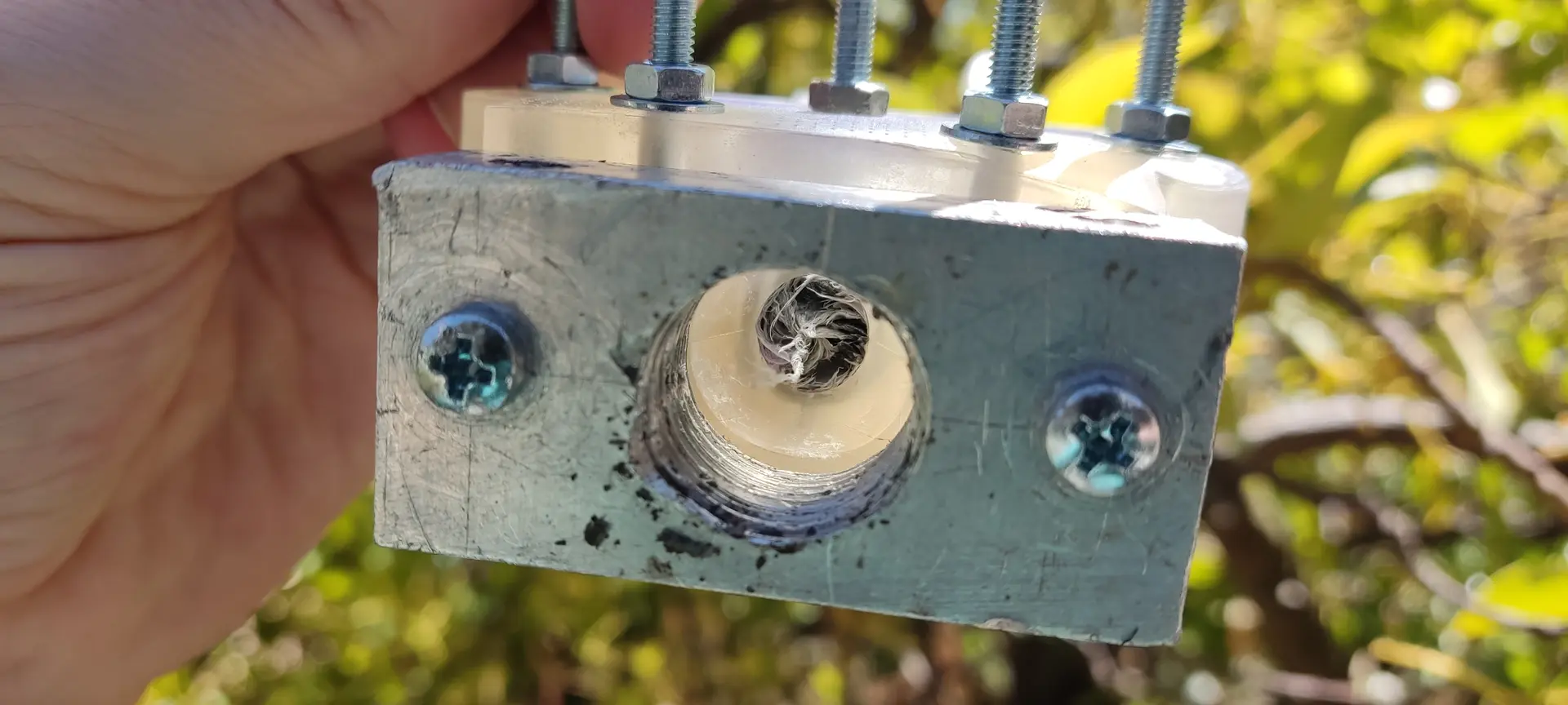
Once I remove the the top mold, I can see that, despite being cracked, the plastic did fill all the spaces ! 🚀
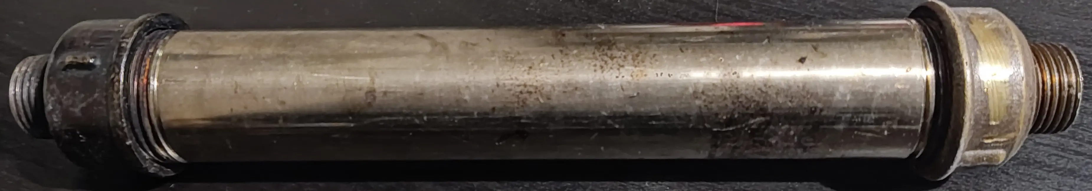
On the bottom side (the insertion side), I unscrewed the metal container and noticed the channel leading to the mold came out as one piece and a little more:
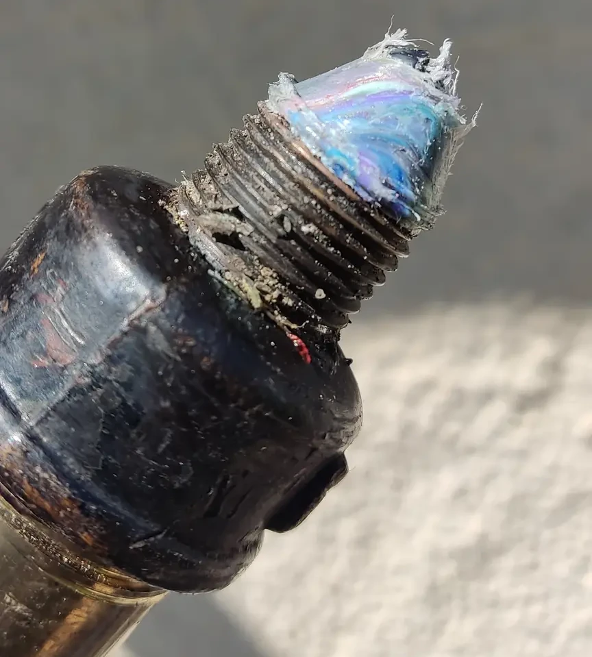
This meant that a little more than I expected was removed from the woggle.
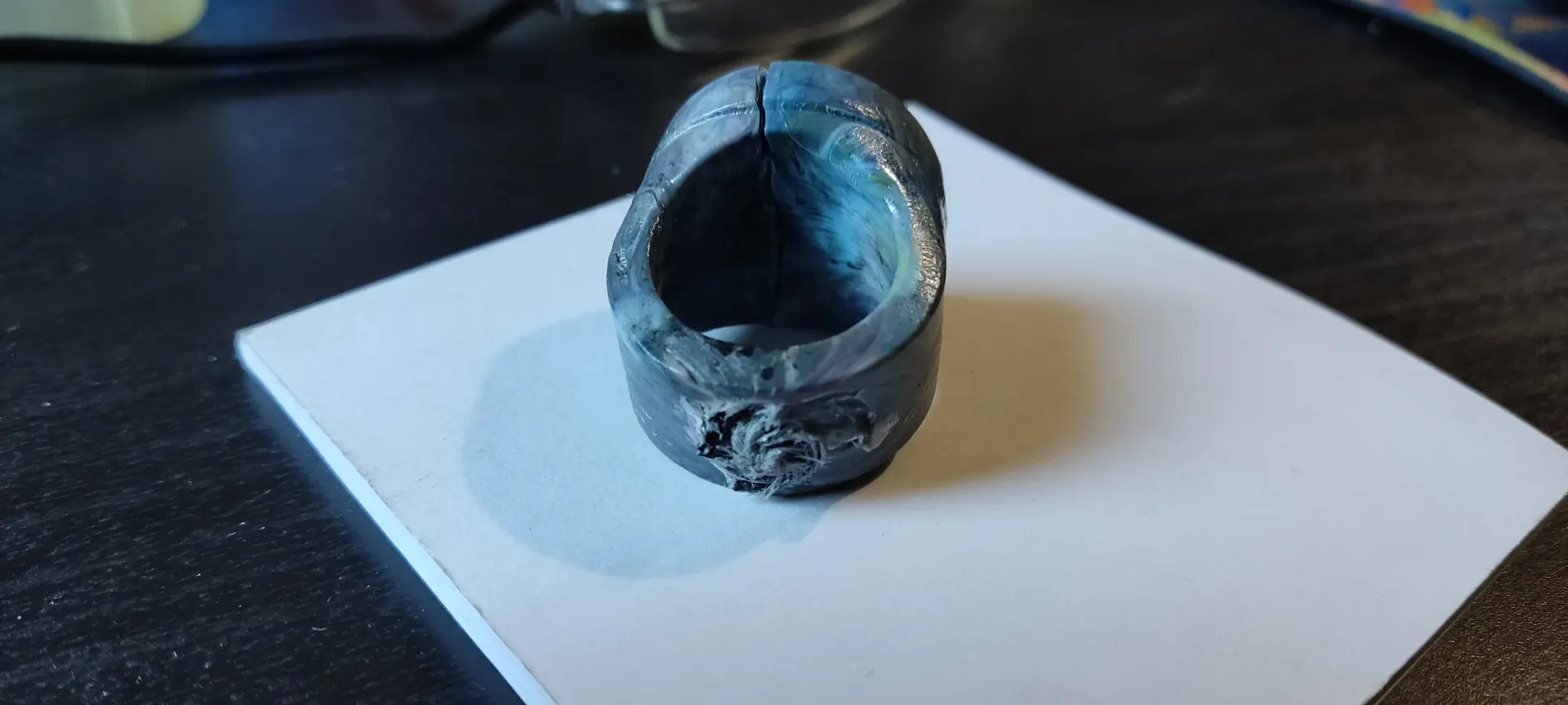
Hero shot
Here’s the final result:
Front:
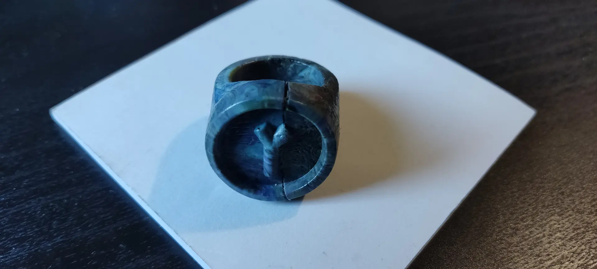
Back:
Conclusion and learnings
- have a generous tolerance for bolt fittings, likely add 0.2 to 0.3 mm in diameter.
- don’t forget that bolts are not all the same size
- be patient and do the proper tilting of the model when printing on the resin printer
- make sure to add generous air vents, and if they don’t come out right, use a drill to open the vents and make sure they are all working
- have a longer channel from the metal container to the mold, or better yet, put it perpendicular to the mold, with a chamber before, so that when unscrewing it, it doesn’t destroy part of the cast. Alternatively, we could also remove the mold first and cut the excess, before unscrewing the metal container
Files
Woggle OpenSCAD model
Printer and resin config
Feature
This week, I got featured in class: