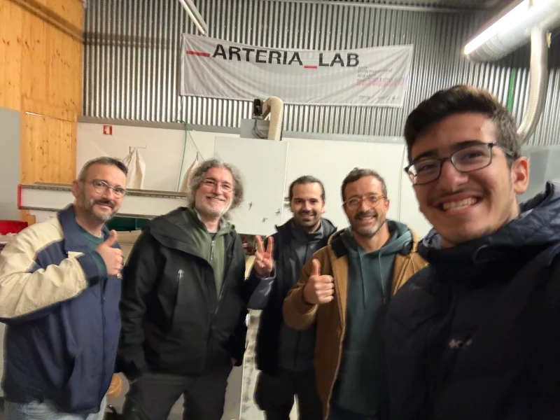
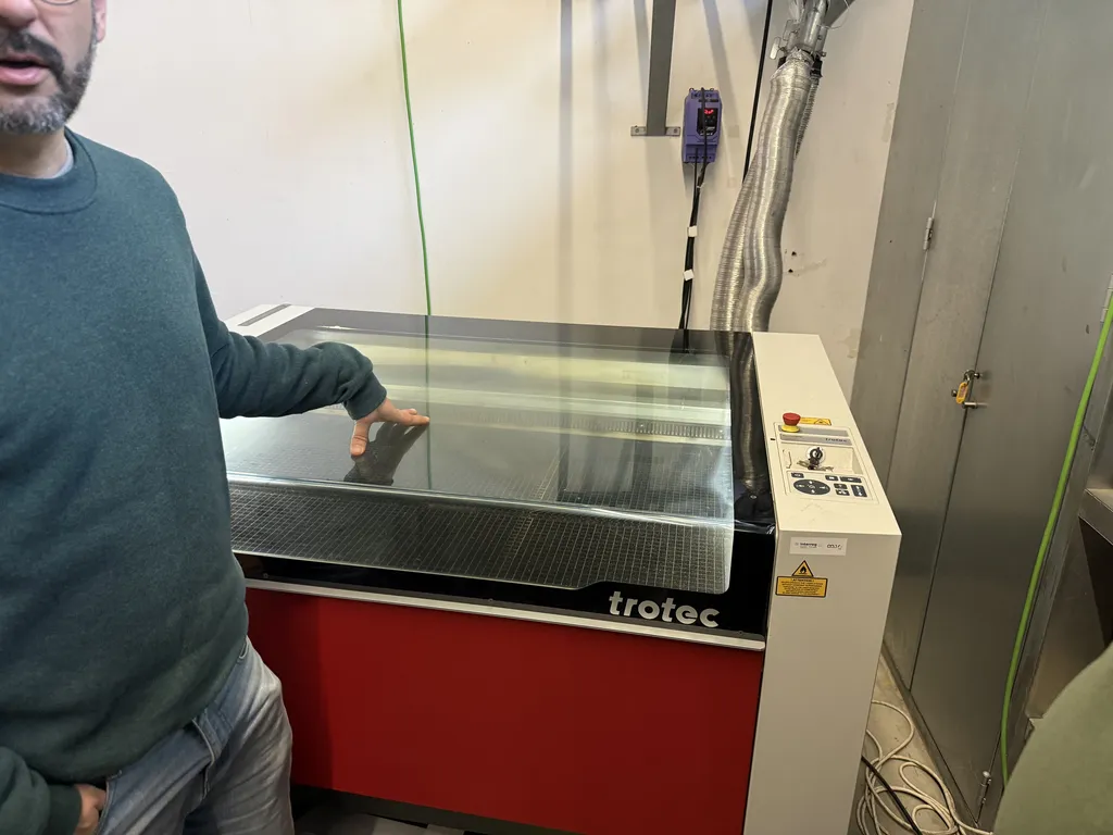
This group assignment took place at FabLab Arteria with Marius Araújo since FabLab Benfica's laser needed some maintenance. It was a nice ~2 hour drive from Lisbon!
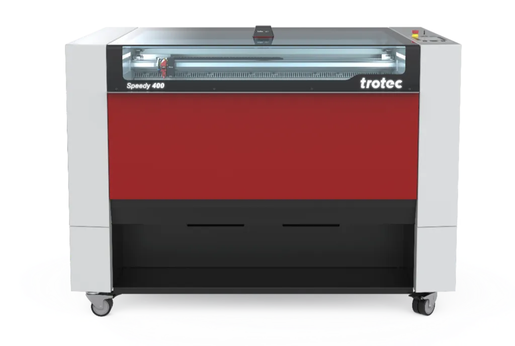
The Trotec Speedy 400 is a high-performance CO₂ laser engraving and cutting machine manufactured by Trotec Laser GmbH, an Austrian company. It's designed for professional applications ranging from single-piece projects to large-scale industrial production.
| Specification | Value |
|---|---|
| Work Area | 1016 x 610 mm (40 x 24 inches) |
| Laser Type | CO₂ w/ ceramic tube |
| Laser Power | 60W (rated), 80W (nominal) |
| Maximum Engraving Speed | 4.3 m/s (170 in/sec) |
| Maximum Acceleration | 5g (50 m/s²) |
| Positioning Accuracy | < 20 µm |
| Interface | USB, Ethernet |
| Supported File Formats | SVG, DXF, PDF, AI, CorelDRAW, and more |
| Lens | 2" |
| Frequency | 500/1000 |
| DPI | 333 |
OptiMotion™ Technology, based on their description:
Real-time optimization of cutting speed and acceleration based on geometry, "perfect" curve quality at fastest speeds, and up to 5x faster cutting than comparable lasers.
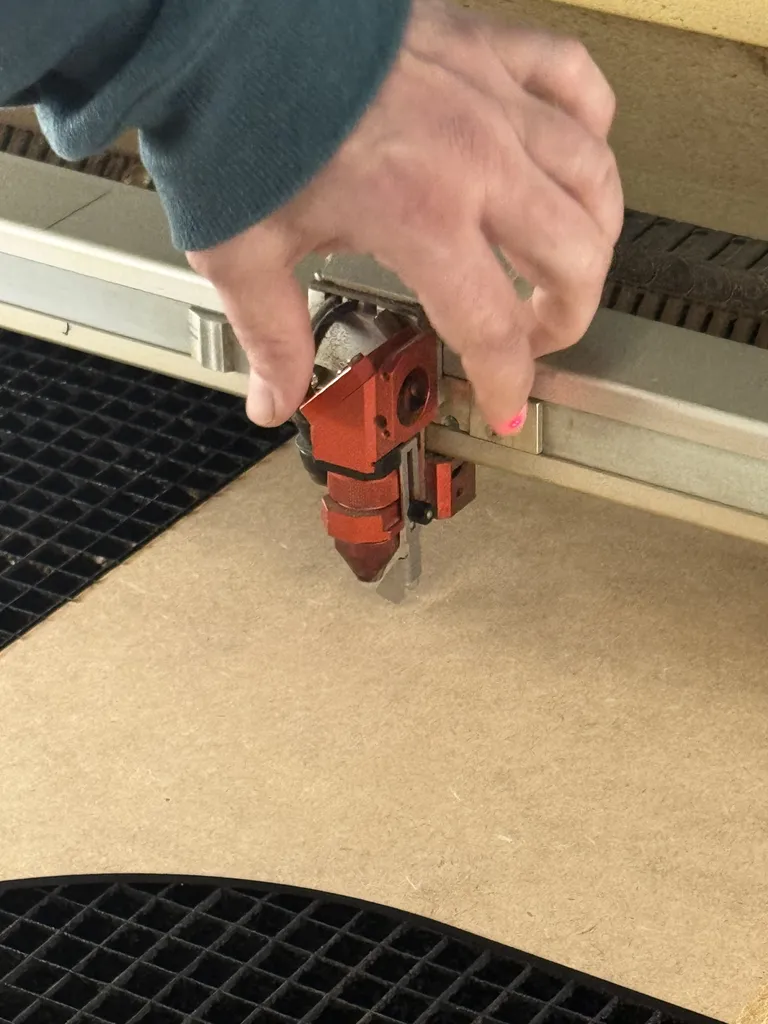
Focus System:
Automatic focus positioning with time-of-flight sensor (essentially, fancy lasers that behave like ultrasound), and a manual focus adjustment is available with provided tools for support.
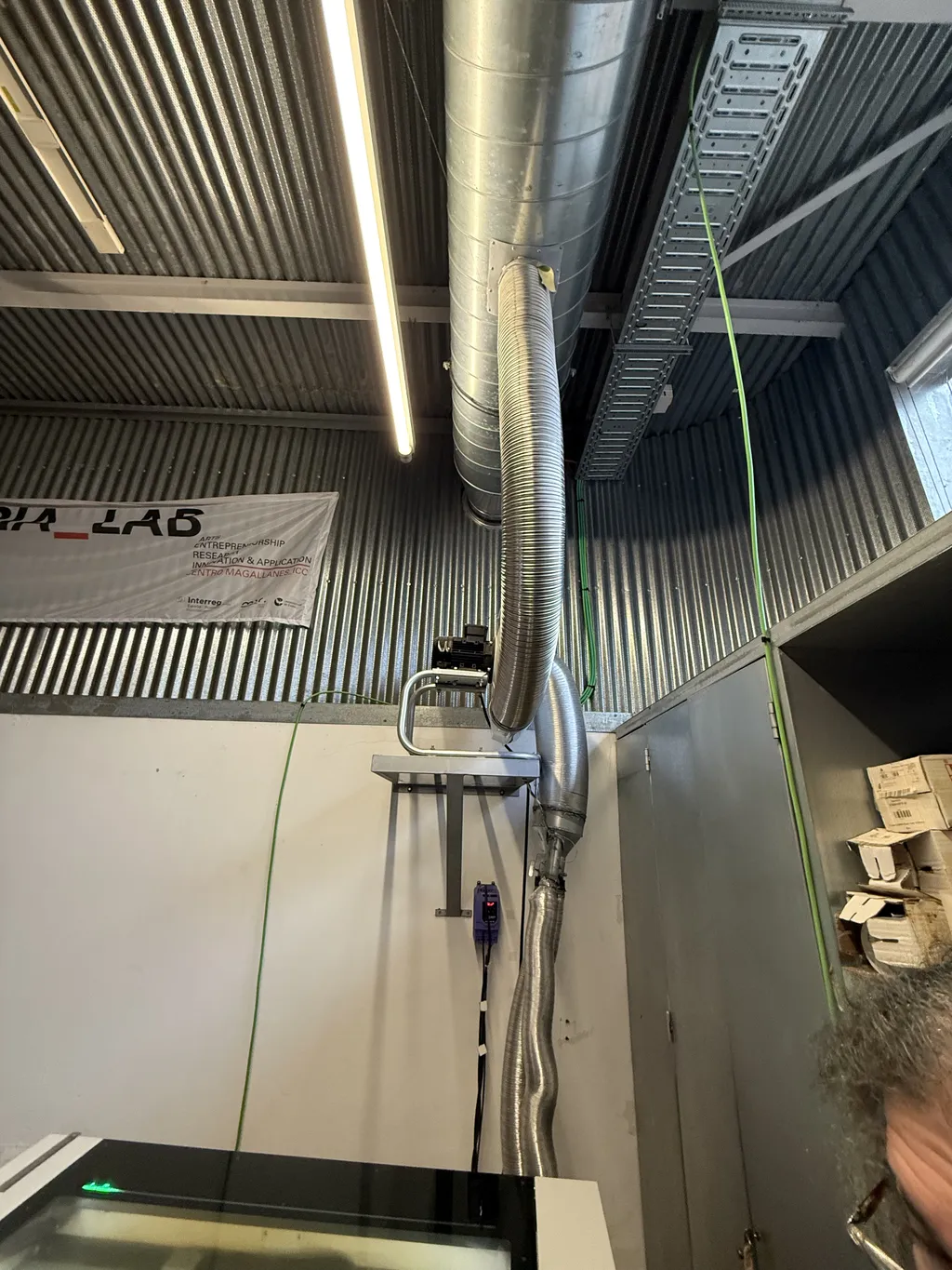
Air Assist & Exhaust:
Integrated air assist system for clean cuts containing powerful exhaust system for fume extraction.
| Class | Risk Level | Protection Required |
|---|---|---|
| Class 1 | Enclosed, safe | None |
| Class 2 | Low power visible (the full Trotec Speedy 400 machine) | Eye protection recommended |
| Class 3 | Medium power | Eye protection required |
| Class 4 | High power (Trotec's laser by itself) | Full safety protocols required |
Safe Materials:
Prohibited Materials:
To test the laser cutter, we created a board with different tests to determine the following:
What is Kerf?
Kerf is the width of material removed by the laser beam during cutting. It's critical for designing precise joints and assemblies. In our parametric design, we would adjust for kerf by adding kerf/2 to each side and subtracting kerf/2 from each side for slots. Here's an image generated by ChatGPT to explain it.
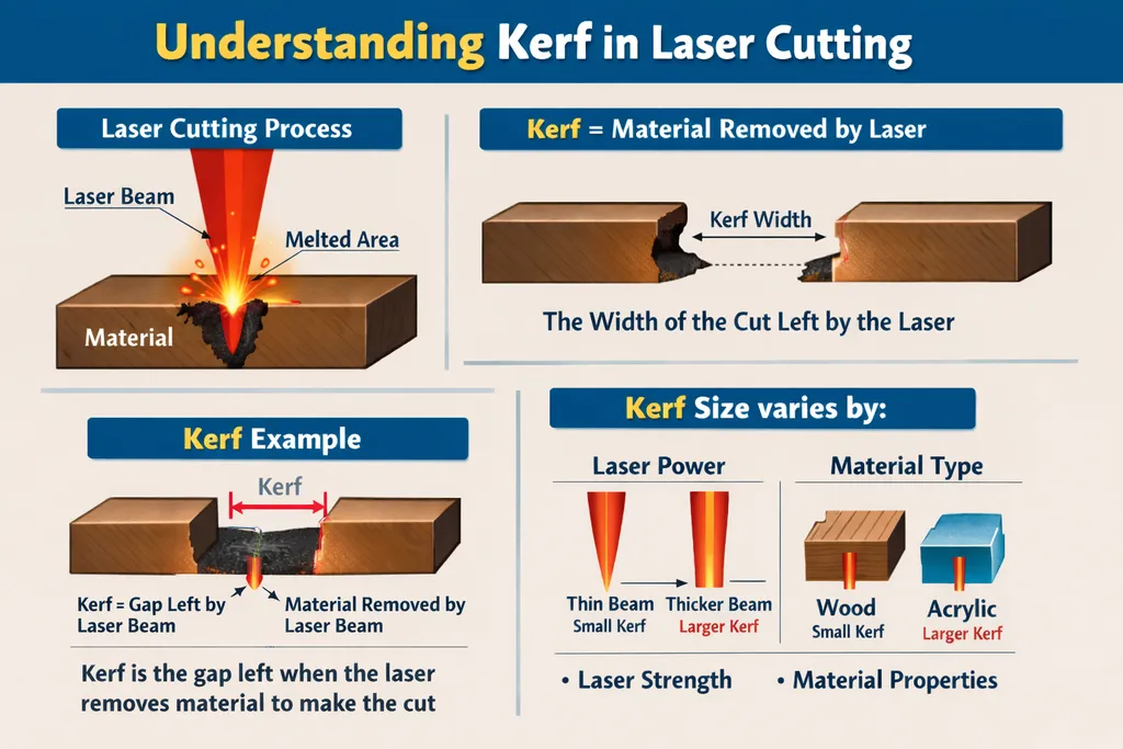
The factors that could affect kerf include laser power (higher power = wider kerf), material type and thickness, focus position, and cutting speed (slower = slightly wider kerf).
For joints in construction kits, it is important to note that cardboard compresses over time, so initial tight fit may loosen. Acrylic and plywood maintain fit better.
The Trotec software uses color mapping to assign different operations. There are 16 colors, with 2 already set; we can customize the rest, but should have the exact colors on our SVG design that gets sent to the laser cutter through its software:
| Color | Operation | Typical Use |
|---|---|---|
| Black | Engrave (raster) | Images, text, fills |
| Red | Cut (vector) | Outlines, through cuts |
| White | Nothing | Layering text on top of engraving |
The processing order should always be: engrave → mark → cut, which prevents material movement during engraving.
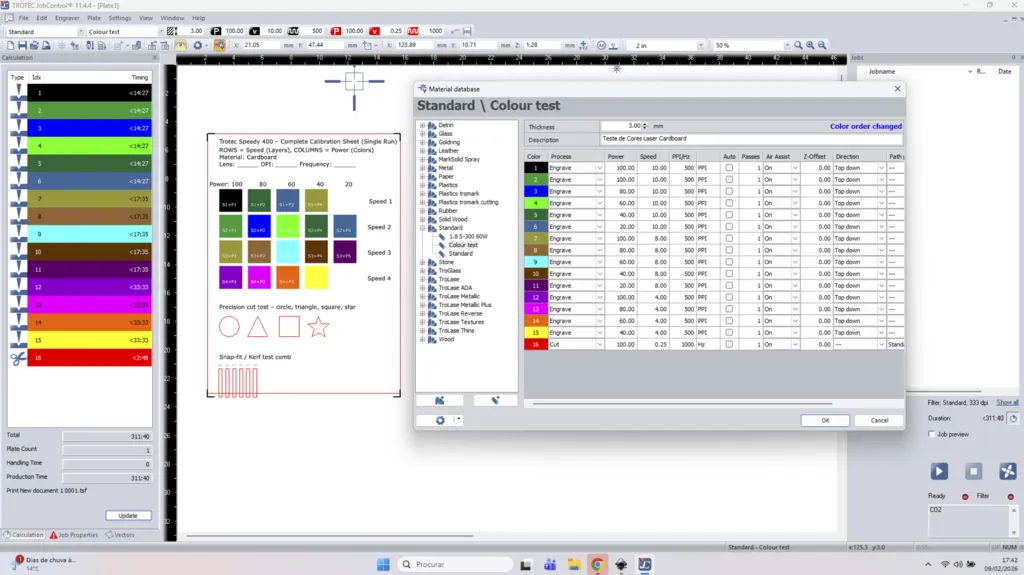
On JobControl, which is Trotec's software for controlling their laser cutters, we could customize a variety of settings to get the best cut/engraving possible:
At FabLab Arteria, Marius told us that usually at their lab they keep the power at 100% and change the speed since that is usually optimum for their uses.
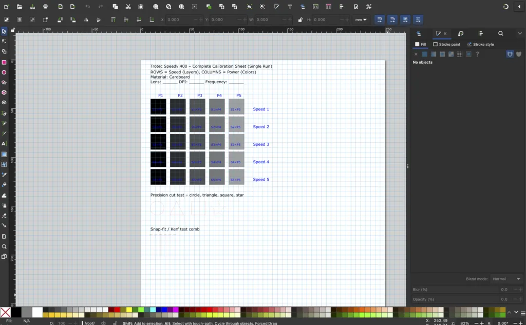
We initially devised the following SVG for the test. While not directly visible, each row of the grid is on a different layer. The plan was to use the raster mode where each shade corresponds automatically to a power setting, and then set each row to a different speed setting.

Unfortunately using layers to map to different settings is not something we could find in the available version of the cutter software. We thus resorted to changing each square to one of the 16 configured colors.
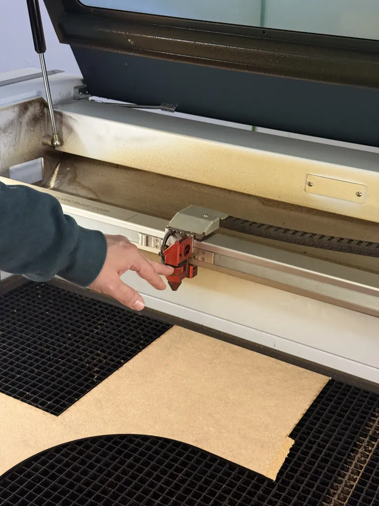
Placing our test board with calibration patterns onto the laser cutter bed, and setting the home of the laser cutter at the appropriate place on our material:
Our original design wasn't appropriately color mapped and didn't have the right SVG template:
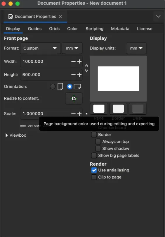
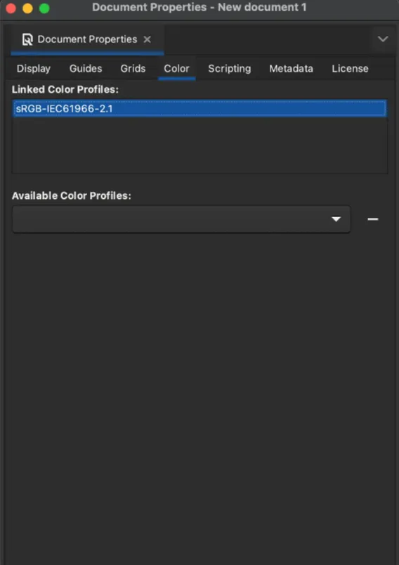
Marius told us that to get the best results and overcome size and alignment issues we should use a 1000 × 600 mm document with RGB as the color profile on Inkscape, put our design there first and then send it to the laser cutter:
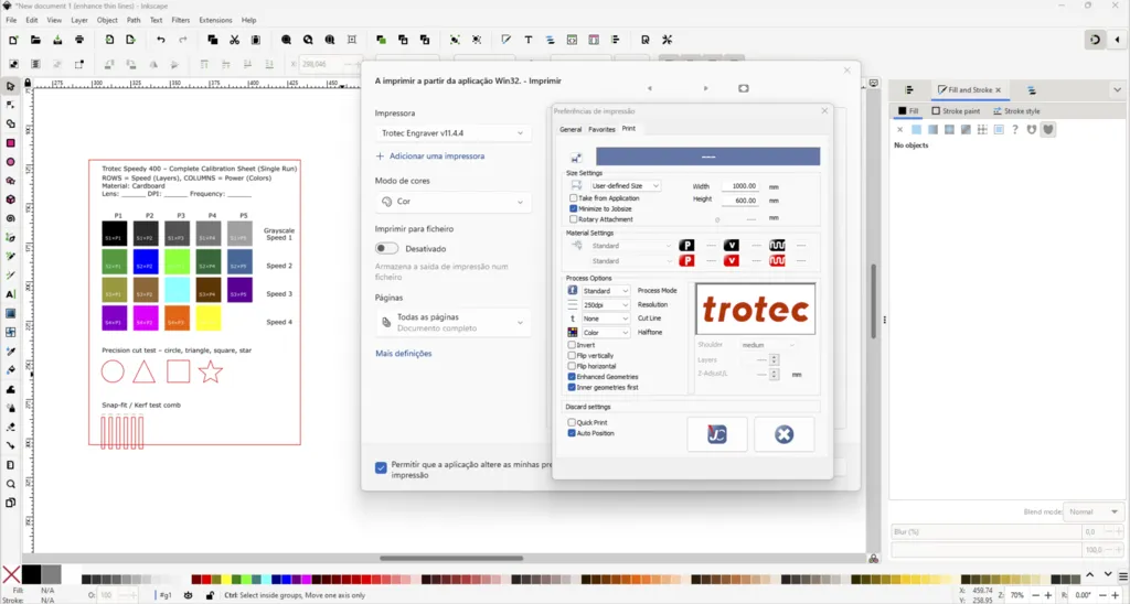
Thus, we did that and mapped the colors to the cutter's predefined 16 (more like 14 since black and red are taken) colors, and imported by "printing it from Inkscape" to the laser cutter software.
Additionally, we needed to change all the red stroke, that would be cut, to "hairline," since it ensures that the laser cutter is only cutting on that line:
An issue we faced was that the laser cutter interpreted greyscale as different colors, so we expected that the first row in our matrix would not be engraved properly:
Also, because of the change of a particular stroke to hairline, the width of the cuttings for the Kerf test was changed and had to be manually adjusted again.
The final file used is here.
Then, we started laser cutting:
Our testing board tested for the following:
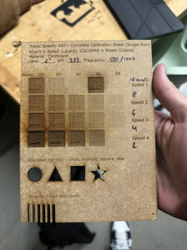
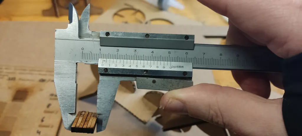
The measured kerf for our 3 mm MDF was 0.1(3) mm, which we measured by taking the cutouts from our board, measuring them, and comparing that measurement to the original combined width of the cutouts in our design. The sum of the 6 cuts ranging from 2.0 to 2.5 mm should be 13.5 mm, but stacking them together, we measured 11.9 mm. Subtracting the modeled 13.5 mm with the measured 11.9 mm, we get 1.6 mm. And if we divide that by the number of cuts (12), we get a total of 0.1(3) mm.