CNC Milling Machine Safety & Testing
Machine Description
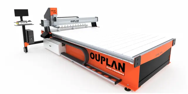
The OUplan Steel 3020 is a compact yet robust CNC milling machine designed for precision fabrication tasks in digital fabrication environments. Built with a sturdy steel frame, it offers a reliable and rigid platform for milling operations on a variety of materials, including wood, acrylic, foam, and soft metals like aluminium.
| Specification |
Details |
| Work Area | 300 × 200 mm |
| Frame Construction | Steel |
| Spindle Type | High-speed rotary spindle |
| Control System | CNC (Computer Numerical Control) |
| Compatible Materials | Wood, MDF, acrylic, foam, soft metals |
Safety Procedures
- Never leave the machine unattended while it is running. Always stay nearby to monitor the operation and be ready to hit the emergency stop if something goes wrong.
- Wear appropriate personal protective equipment (PPE). Safety glasses are mandatory to protect against flying chips and debris. Avoid loose clothing, jewellery, or long untied hair that could get caught in the spindle.
- Resist the temptation to hover your hands over the cutting area. Never do this. The spinning tool can cause serious injury in a fraction of a second.
- Ensure the workpiece is securely clamped. A loose workpiece can be grabbed by the cutter and thrown, creating a dangerous projectile. Always double-check your fixturing before starting a job.
- Verify your toolpaths and zero points before cutting. Run an air pass first if you are unsure, to confirm the machine will not crash into clamps or travel beyond the work area.
- Know the location and operation of the emergency stop button. Be prepared to use it immediately if you notice unusual vibrations, sounds, or the tool breaking.
- Keep the work area clean and organised. Remove tools, offcuts, and clutter from the machine bed and surroundings before operating.
- Never modify feeds, speeds, or tool settings while the spindle is running unless you are experienced and the machine's interface explicitly supports it.
- Use appropriate cutting parameters (feed rate, spindle speed, depth of cut) for the material being machined. Incorrect settings can cause tool breakage or fire, especially with materials like acrylic.
- Ensure adequate ventilation or dust extraction. Milling produces fine dust and chips that can be harmful to breathe and can also pose a fire risk with certain materials.
Designing a Testing Board
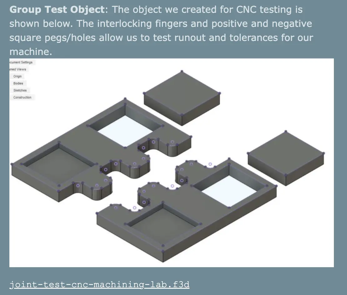
To test the CNC machine, we designed a testing tool similar to laser-cutting and 3D printing, taking inspiration from Jason Goodman's group assignment.
Parameters Tested
-
Runout: We tested this by cutting a square pocket and a matching block at the same dimensions. If the block fits snugly, runout is minimal.
-
Alignment: We cut straight lines along X and Y and checked with a square to make sure everything was perpendicular.
-
Fixturing: We used the T-slot clamps on the Ouplan's bed, placing them around the edges of our MDF sheet and making sure they wouldn't be in the way of the toolpath.
.jpeg)
-
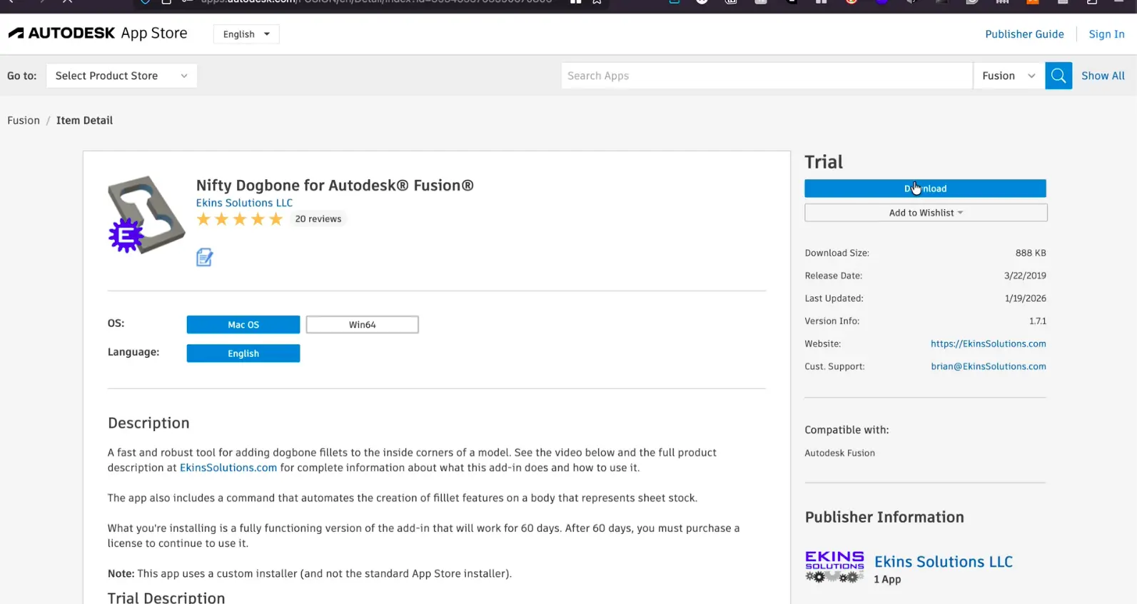
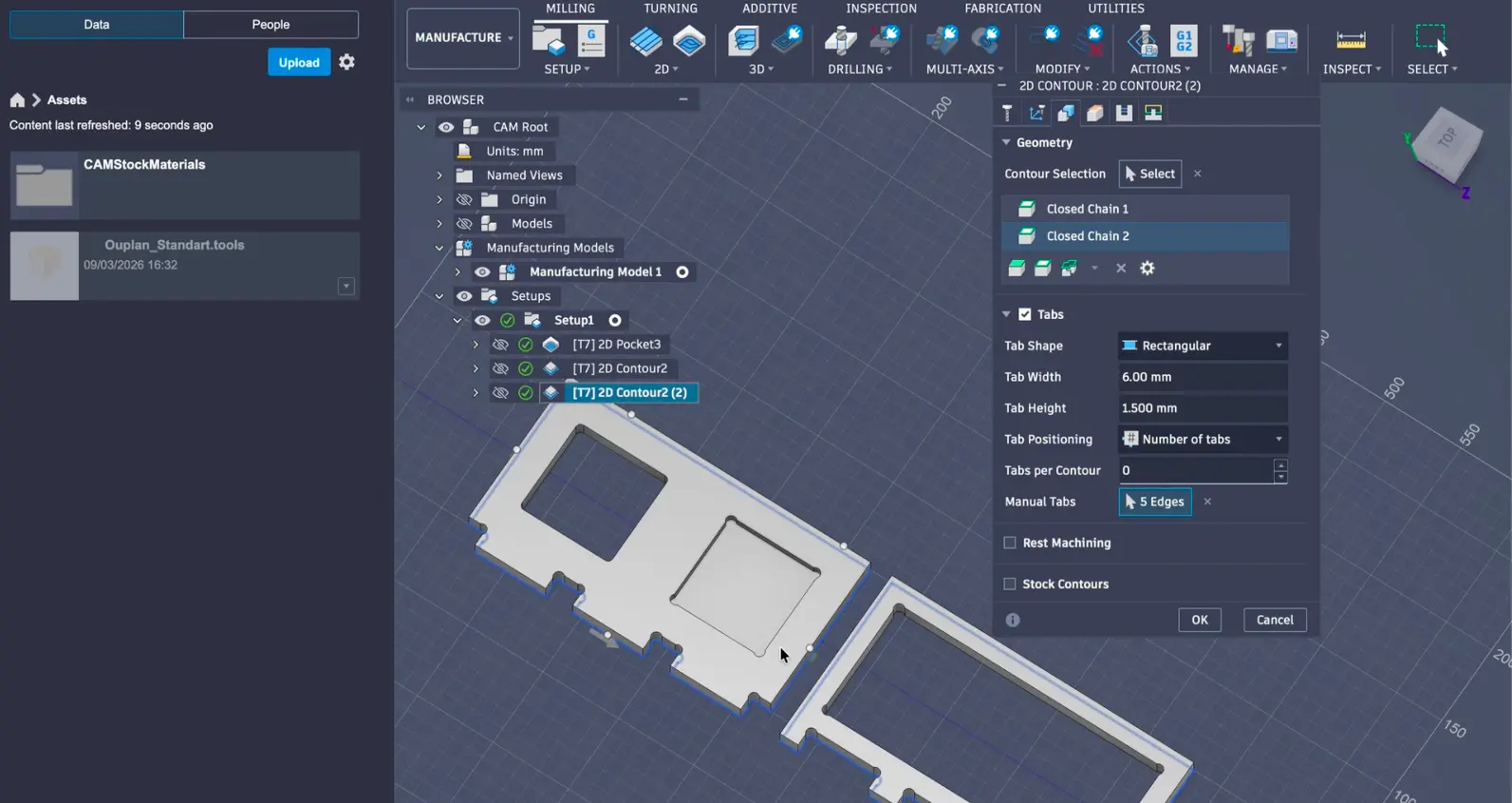
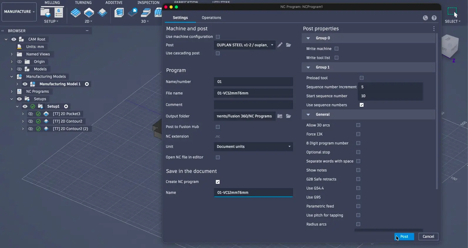
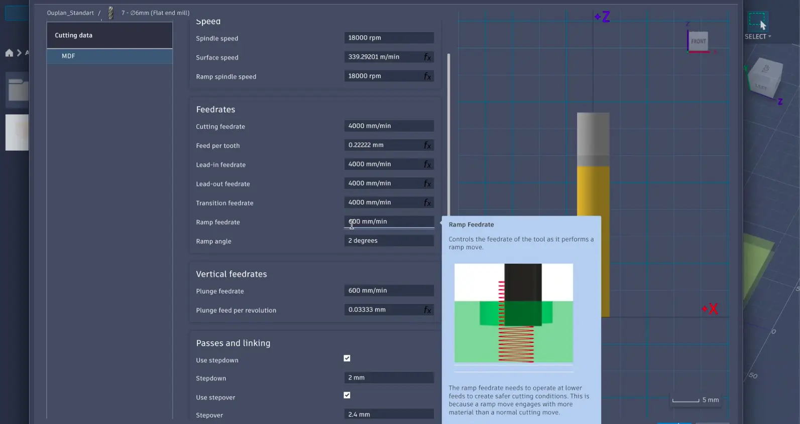
Speeds: We used the Ouplan tool library in Fusion 360 which already has tested speeds for each tool. We were cutting MDF with the 6mm flat end mill (Tool 7).
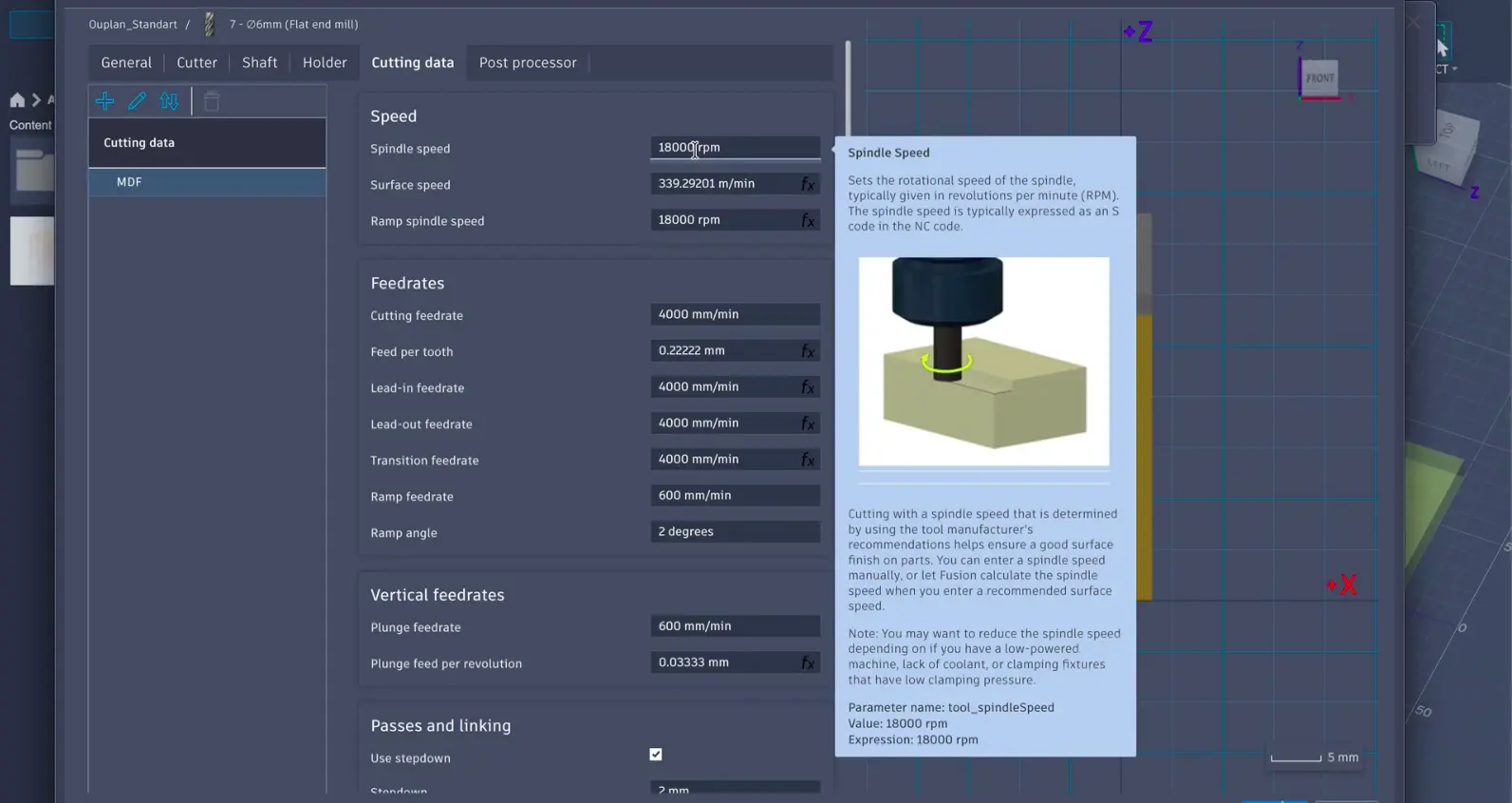
-
Feeds: Feed rate is how fast the tool moves through the material (mm/min). Again we used the defaults from the Ouplan tool library.
-
Materials: We went with MDF for our test because it's consistent, has no grain direction, and machines cleanly.
-
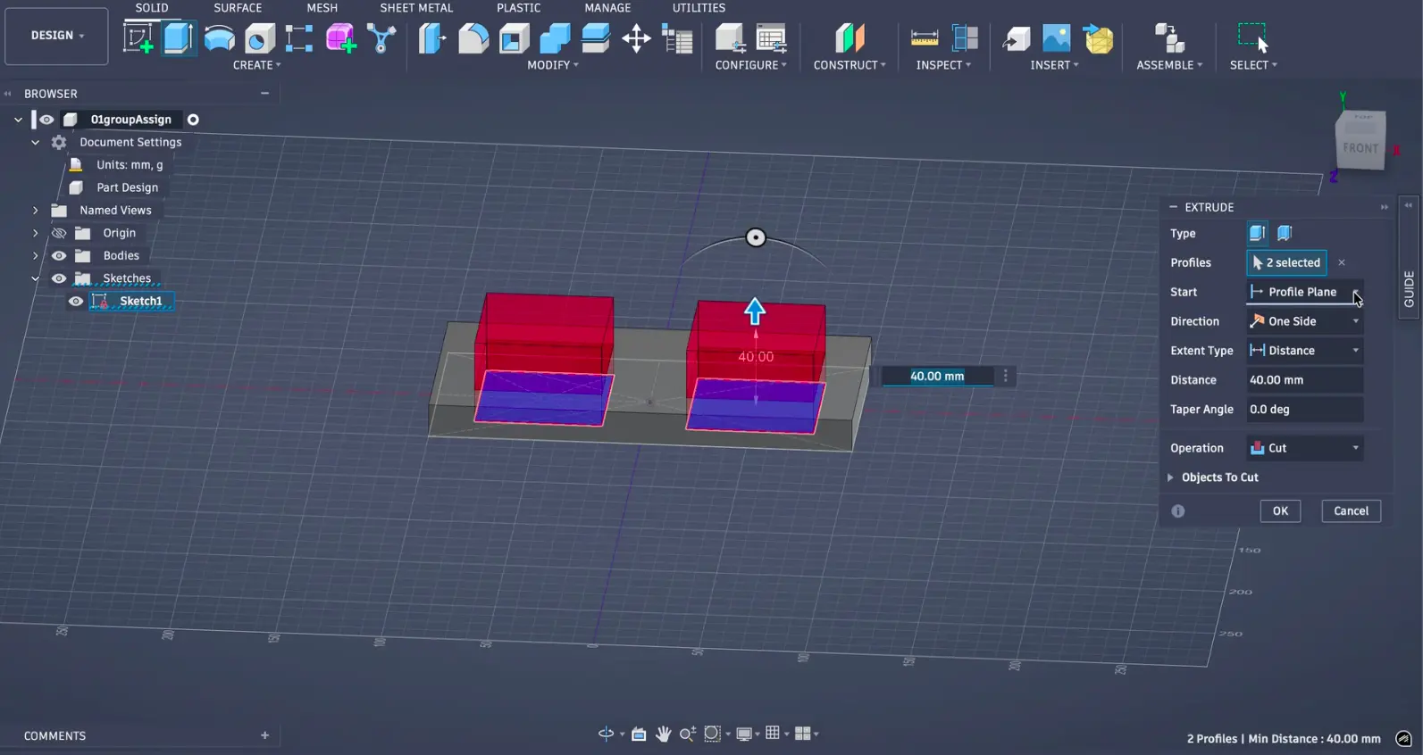
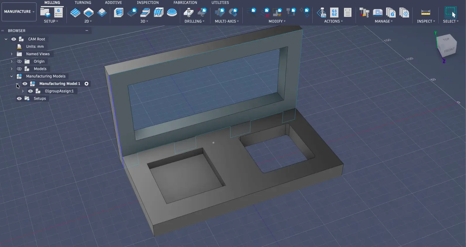
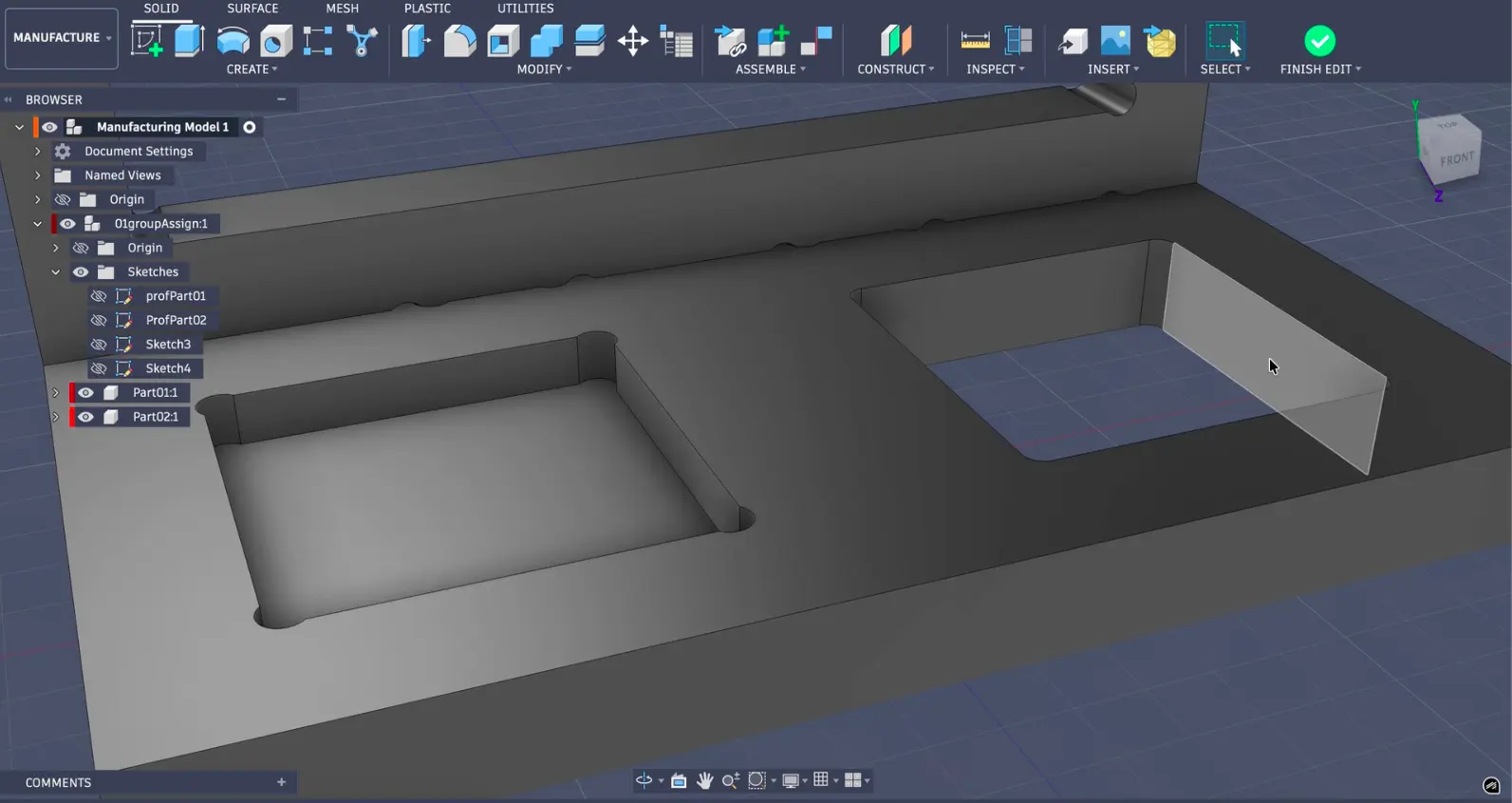
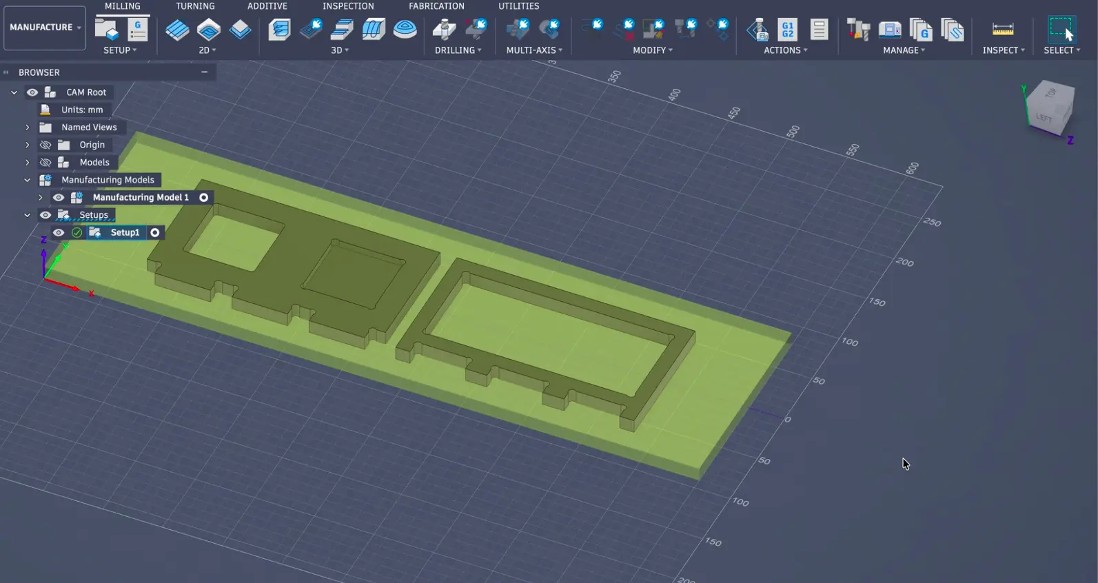
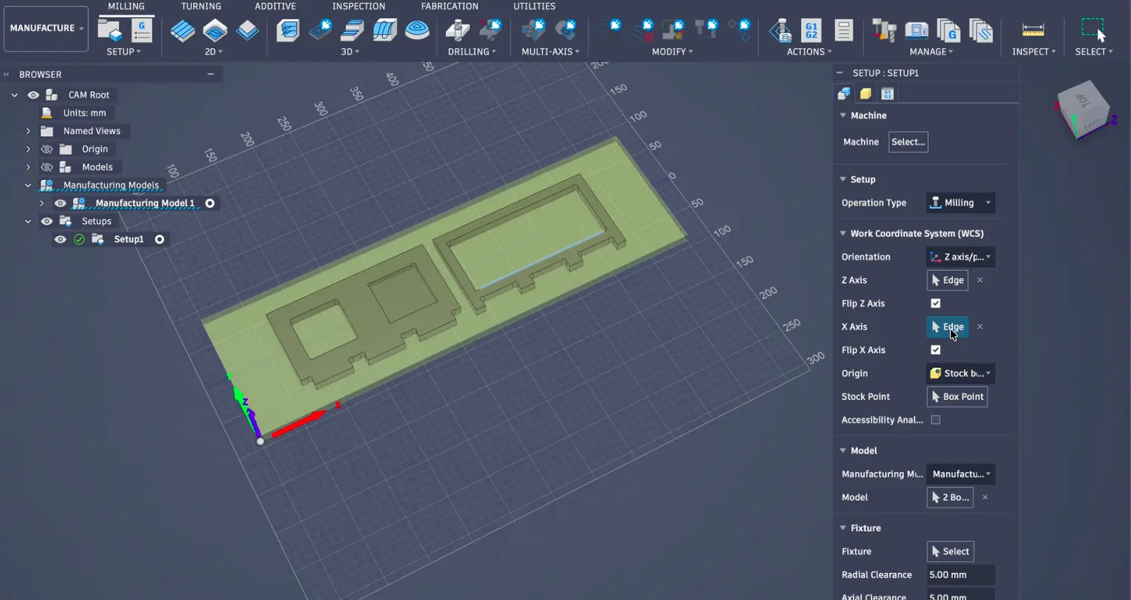
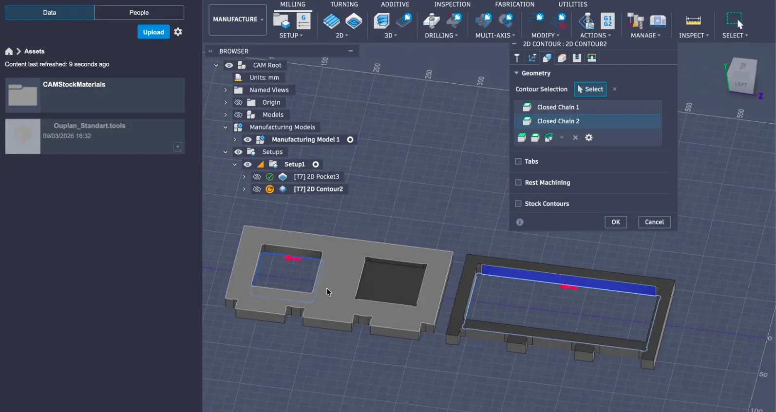
Toolpaths: We set up our toolpaths in Fusion 360's Manufacture workspace. For our test board we used 2D Contour for the cut-through shapes and 2D Pocket for the shallow recessed areas.
The Milling Process
-
Turning on the machine: We turned on the compressed air system, powered on the machine, and opened InoCAM.
.jpeg)
.jpeg)
-
Securing the material: We placed our MDF sheet on the bed and clamped it down.
.jpeg)
-
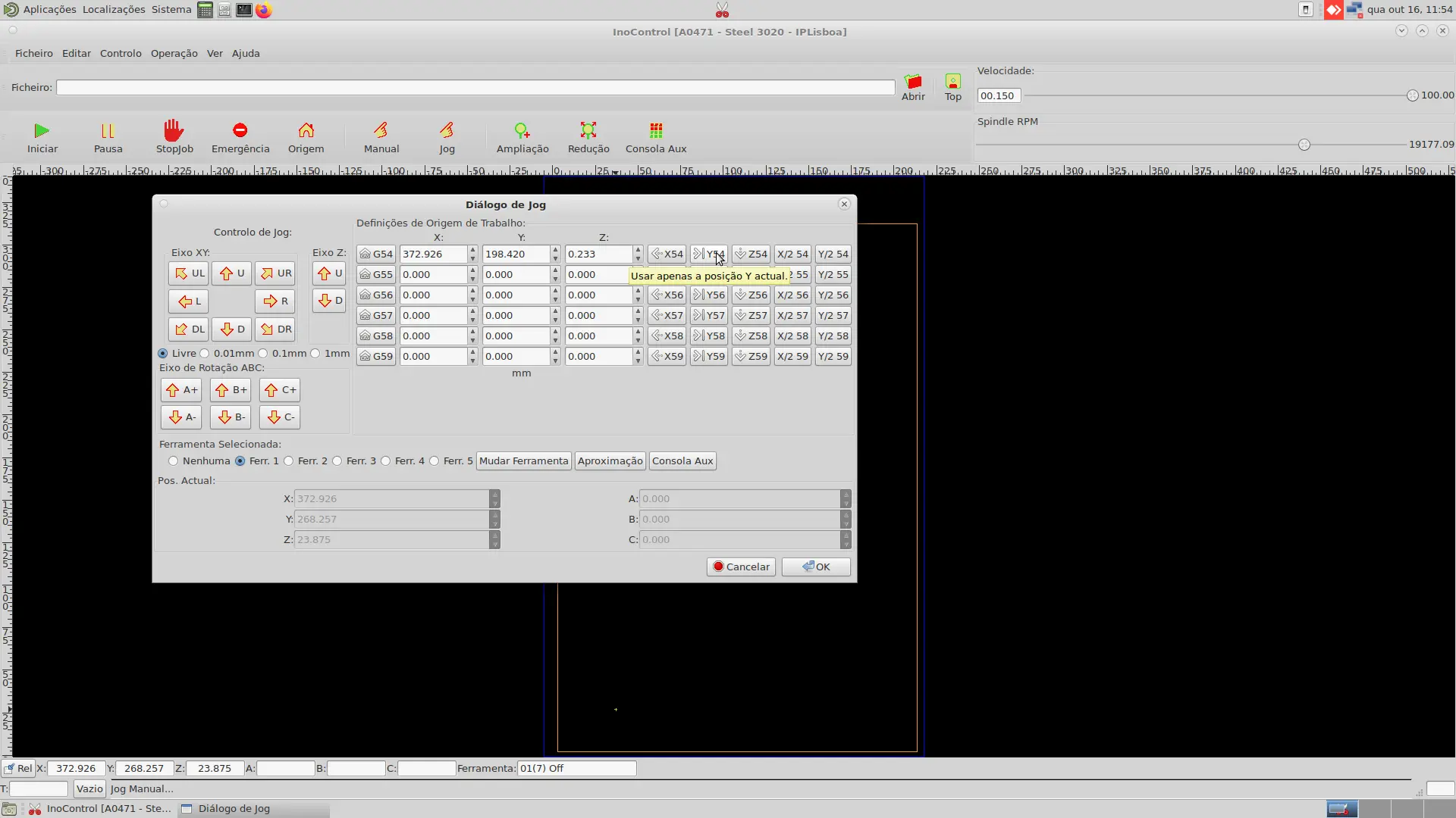
Setting the origin (WCS): We set the work coordinate system using Manual and Jog modes.
-
Loading the G-code: We loaded the .nc file into InoCAM and simulated the toolpath.
-
Running the cut: We started the job and monitored the process.
.jpeg)
-
Finishing up: We removed the clamps, cleaned up, and powered down.
.jpeg)
Machine Testing Results
.jpeg)
After measuring the test board, we found out that our machine had about 0.1 mm kerf, but overall, the settings we tested worked well for the MDF we were utilizing.