group project:
      do your lab's safety training
      test runout, alignment, fixturing, speeds, feeds, materials, and toolpaths for your machine
individual assignment:
      make (design+mill+assemble) something big (~meter-scale)
      extra credit: don't use fasteners or glue
      extra credit: include curved surfaces
Group work
Our group's documentation of the lab safety training and calibration and analysis of finished parts is here.Unfortunately this group page does not address all the specific questions in the group assignment. Here's a summary of what we found in our testing:
Group Test Object: The object we created for CNC testing is shown below. The interlocking fingers and positive and negative square pegs/holes allow us to test runout and tolerances for our machine.
joint-test-cnc-machining-lab.f3d
Runout: Runout is wobble in the tool as it spins. If this is minor, it increases the width of the cut kerf. More seriously, runout can cause vibration, tool damage, and tool breaks. We tested for runout by cutting a square hole and a square block exactly the same size (see above picture). If runout occurs, the hole will be cut too big and the block too small, so there will be a loose fit. We did not observe any significant runout: the finger joints fit together tightly, and the block was actually slightly too big to fit into the hole by less than 0.5 mm.
Speeds and Feeds: We used the default speeds and feeds built in to the VCarve software we used for CAM setup. For our 1/4" downcut flat-end mill, we cut at 100 inches per minute, 1/8" depth of cut, 14,000 RPM.
Materials: We used only one material for our group work, in the interest of time. This was 1/2" soft pine plywood.
Toolpaths: We used two different toolpaths to create the design shown above. We used a "contour" toolpath to cut the overall outlines, and a "pocket" toolpath to cut the shallow pockets in the part. We used tabs to ensure that the part didn't break loose while being cut, and we used "dogbone fillets" to ensure the round bit cut all the way into our square corners.

Individual Project: Spiral Sphere
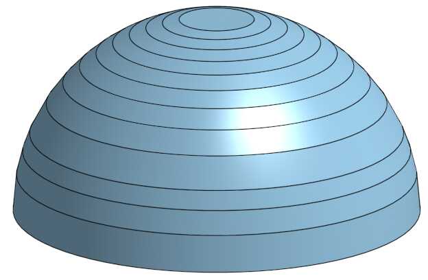
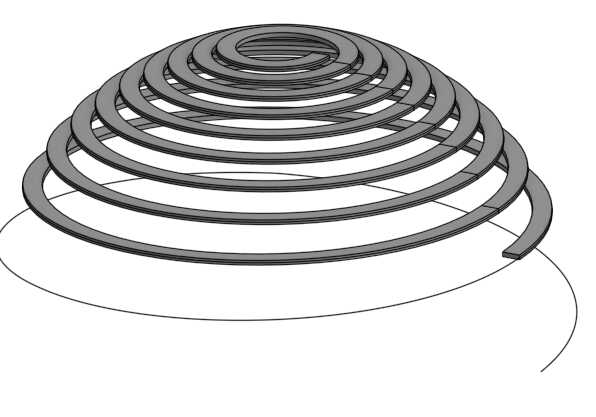
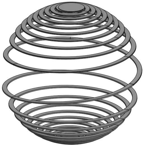
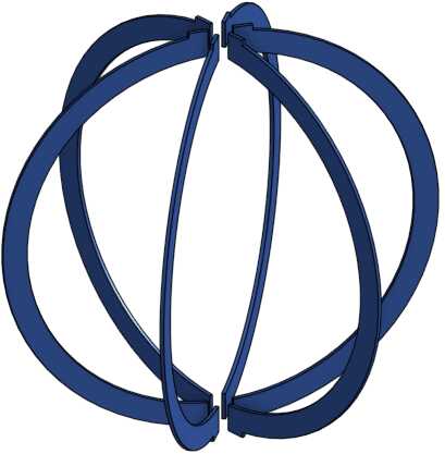
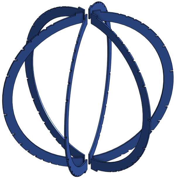
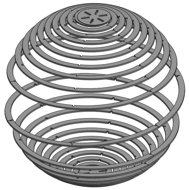
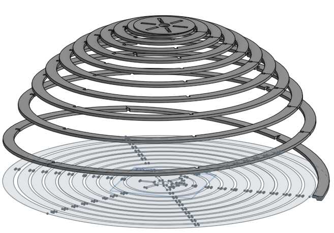
I decided to dive into the extra credit, focusing on curved and twisted surfaces that fit together without fasteners. Hopefully. I wanted to explore the idea of making something large by unwrapping or spiral-slicing, like you get a surprising amount of spiral-cut french fries out of one potato, or how they make plywood by spiral-slicing a log into thin sheets. I was also motivated by the flat-packed designs of Ikea, and specifically this award-winning lamp.In the end I decided to make a sphere in which each hemisphere is a single spiral cut from a flat sheet of wood, forming a spherical helix. The helix will be supported by internal "longitude" ribs. Everything will fit together with interlocking slots: if I do it right, the plywood helix will provide inward compressive stress, and the ribs will provide outward stress, holding it all together as a "tensegrity" structure. But I bet it'll need glue for additional strength.
But I'm going to have to make some sacrifices in "making it big". I'm not confident that half-inch plywood will twist and bend the way I want it to, so I'm going to use 3/16" plywood, which we only have available in 24 x 36" sheets, as it's typically used in the laser cutter. I plan to use a 1/8" cutting bit for better detail. Also a 4-foot-diameter sphere isn't very useful, but a 2-foot-diameter sphere could be made into a cool lamp or chandelier. So, "big but not too big" is my plan.
With these materials, this project could be done entirely on the laser cutter, but the CNC will hopefully give a better surface finish.
OnShape Design
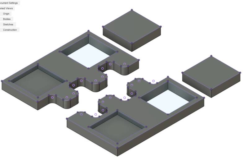
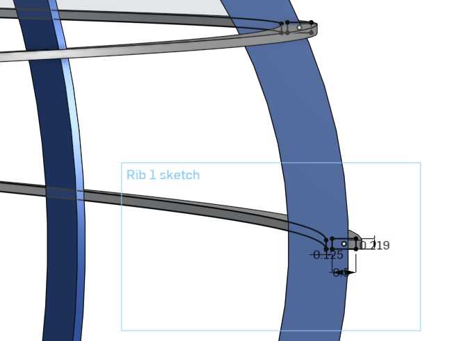
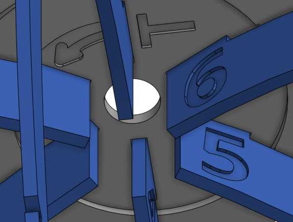
Alignment and positioning is crucial for this. I have to design the whole thing in 3-d first, to make sure the interlocking slots are at the right height to give a smooth spiral curve. Each of the ribs will have a different set of slots, so everything has to be numbered and keyed. Here's my OnShape design process: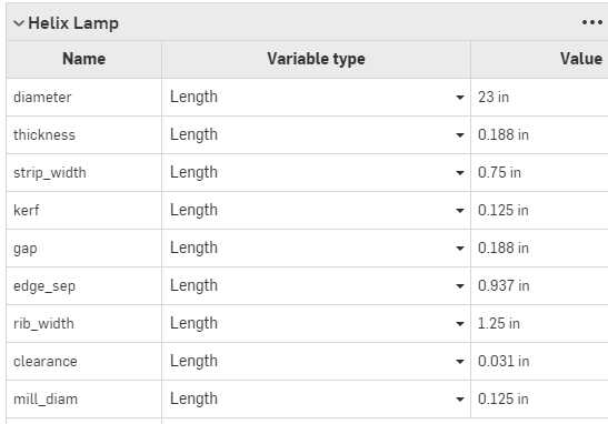
Machining Preparation
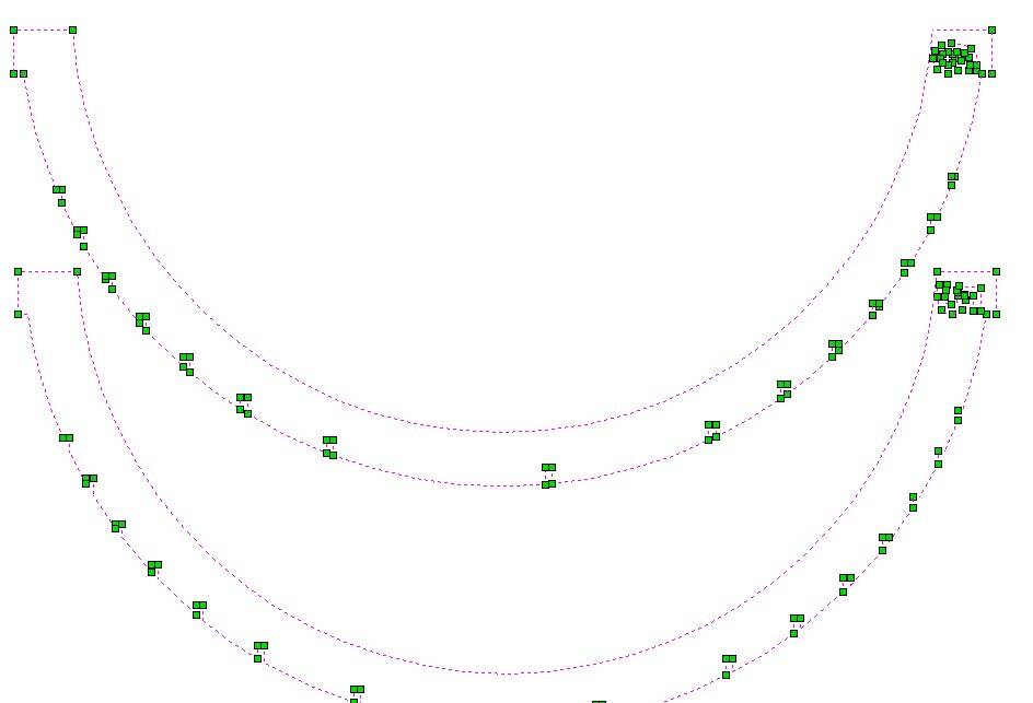
... and here's where the trouble started. I expected to have trouble with fitting the parts together, getting the flexibility of the material wrong and so on, but I didn't expect to spend five hours trying to turn the SVG output from OnShape into toolpaths for the CNC. I ran into two major setbacks in this process. First, I designed the model expecting to use 3/16" plywood, but we only had 1/8" available. Not a problem for a parametric design! Just change my #thickness parameter and ... countless errors. The overall design changed just fine, but the number of slots deep enough to be cut changed, so OnShape couldn't find necessary surfaces. A lot of manual cleanup was needed. Second, when I sent the finished SVG file to VCarve, our CNC's toolpath software, I found that OnShape makes terrible vector files. There were many duplicated paths superimposed on top of each other, and worse, OnShape doesn't export sketches as continuous paths, but as individual line segments. This means VCarve has no way to know which part of a shape is "inside" vs "outside" when cutting. VCarve does let you join path segments together ... one. at. a. time. And there are hundreds.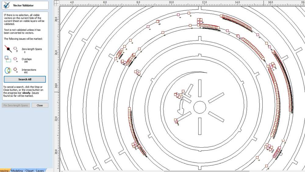
- Export the helices from OnShape as a STEP file.
- Load the STEP file into Fusion 360.
- Create a sketch and project the helix shape onto a 2-d plane.
- Remove extra line segments from the sketch and export it as a DXF file.
- Open the DXF in Adobe Illustrator. It still has broken paths but not as many.
- Select all, then Object/Path/Join Paths. Clean up extra line segments.
- Export the file as an SVG.
- For some mysterious reason, Illustrator rescales the file so it's 3/4 of the original size. No idea why, but it can be un-scaled in VCarve.
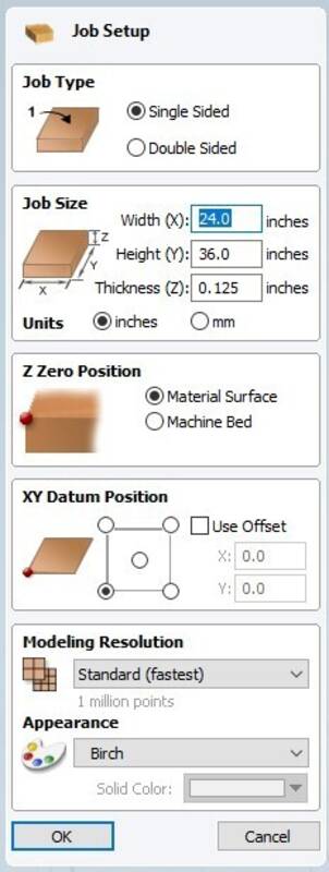
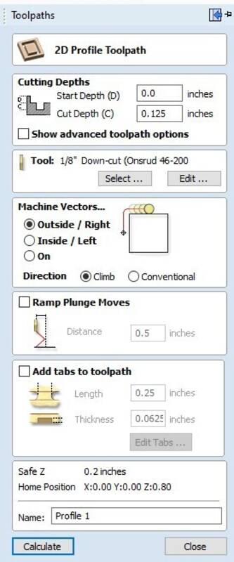
- Set up the overall job parameters. For my project the workpiece is 24" x 36" in X and Y, 0.125" in Z.
- Import the SVG file into VCarve.
- The engraved numbers and letters will be done first, while the wood is relatively intact.Create a new "Pocket" operation, select the letters and numbers, and make the pocket depth 0.0625" (1/16"). Create a new tool setting for our 1/8" downcut endmill. Generate the toolpath.
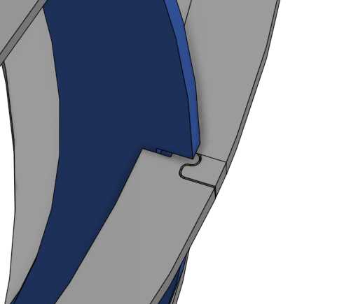
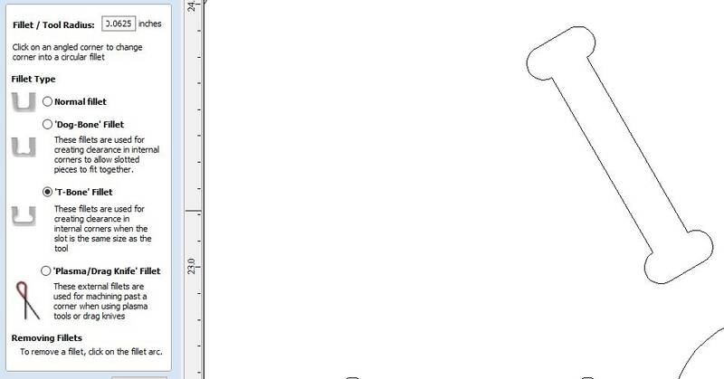
- Create "T-bone fillets" for the slots where the ribs fit into the poles. VCarve makes this easy with its fillet tool.
- Now cut out the internal slots and holes. Create a "Profile" operation, cutting all the way through (0.125" deep), cutting on the Inside.
- Now cut out the shapes. Create a second Profile operation, cutting all the way through, cutting on the Outside. There's no need for fillets here, I included clearance for the tool in the original design because it's just too many fillets to do one at a time.
- Add Tabs to the ribs to keep them secure while cutting. I think it's hopeless to hold the spiral pieces together with tabs, so I'll use double-sided tape and hope for the best.
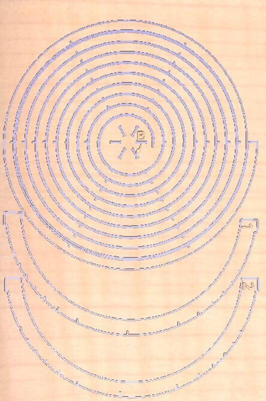
- Preview Toolpaths to see what the wood will look like after it's been cut.
- Ready to go! Select all three toolpaths and choose "Save Toolpaths".
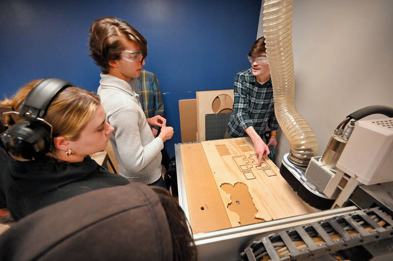
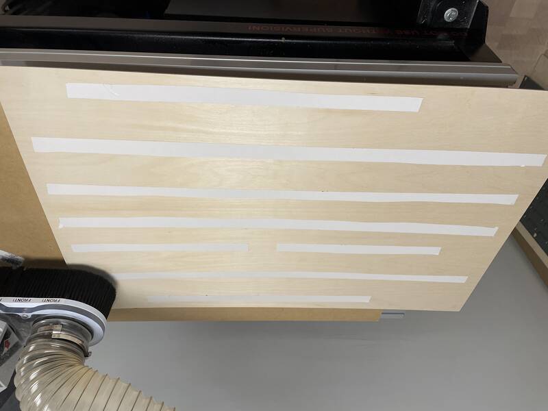
Cutting it out
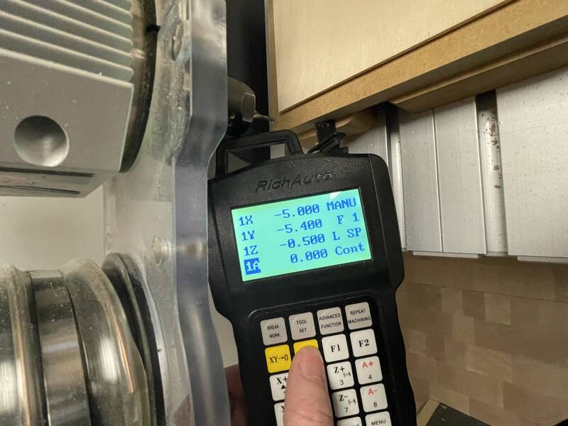
Once the toolpath files were created, I started cutting the patterns. Step-by-step instructions on using the machine are documented in the group work. I used double-sided tape to hold the work, since otherwise I'd need dozens of tabs to hold the spirals together, which would be annoying to post-process and probably wouldn't work.The only real problem I had in the cutting proces was that the bed wasn't adequately leveled, so the cut didn't quite go deep enough in some areas. I fixed this by "cheating" the z-zero point down about 0.5 mm below the surface of the wood.
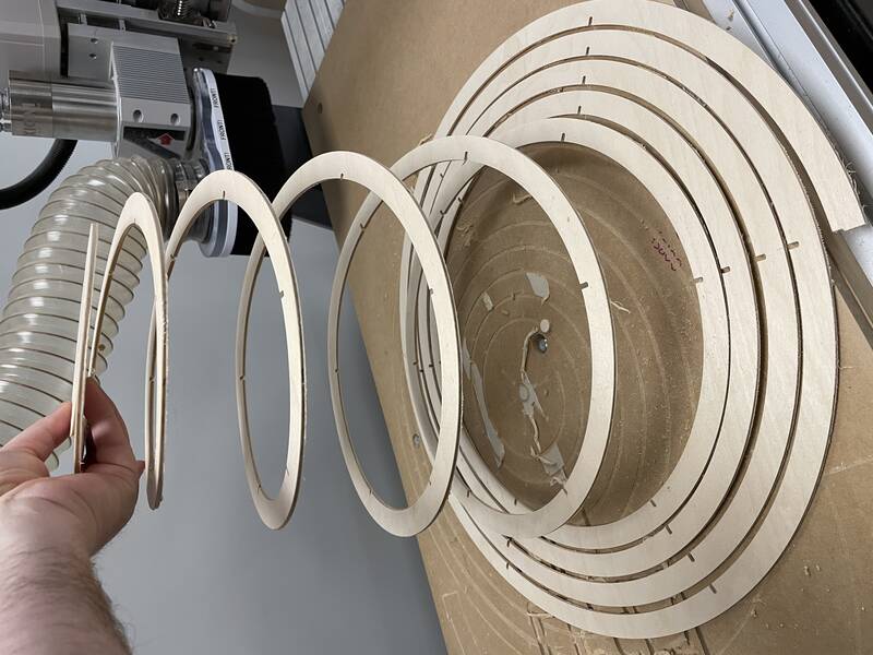
Once the first sheet was cut, I checked the spiral for springiness -- it was even more flexible than I really wanted, since I had to use 1/8" material instead of 3/16" -- but better that than too stiff. I also test-fit the slots, and found that I'd used too much clearance -- 1/32" was just too sloppy a fit. So I re-did the entire design again with 1/64" clearance. As before, this is in theory a quick parameter change, but in practice it took hours of manual work to repair broken constraints and missing surfaces and create new cut files. I also had to deal with Illustrator's bizarre re-scaling of my DXF files, and in one case I got that slightly wrong and ended up a rib that was too big and had to be recut.
And then I got impatient while peeling the parts off the bed, and snapped one of the spirals at a flaw in the wood, and had to re-make it.
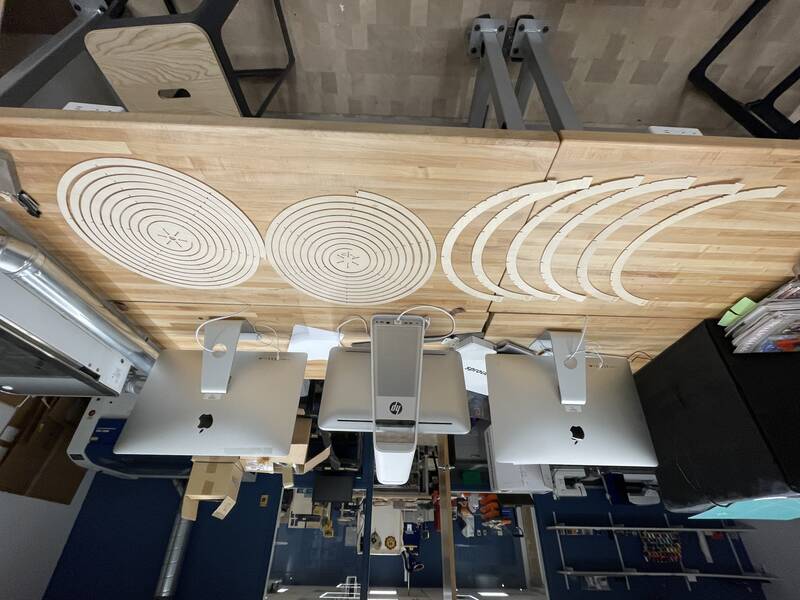
Finally, finally I managed to cut all my parts. I took off all the bits of tape and sanded their edges.
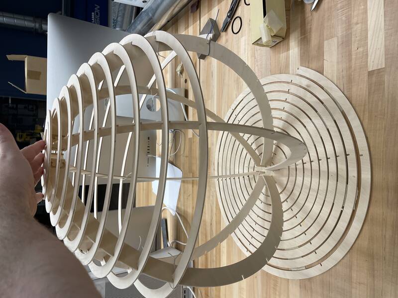
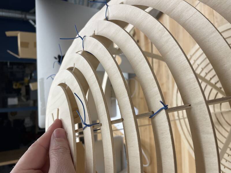
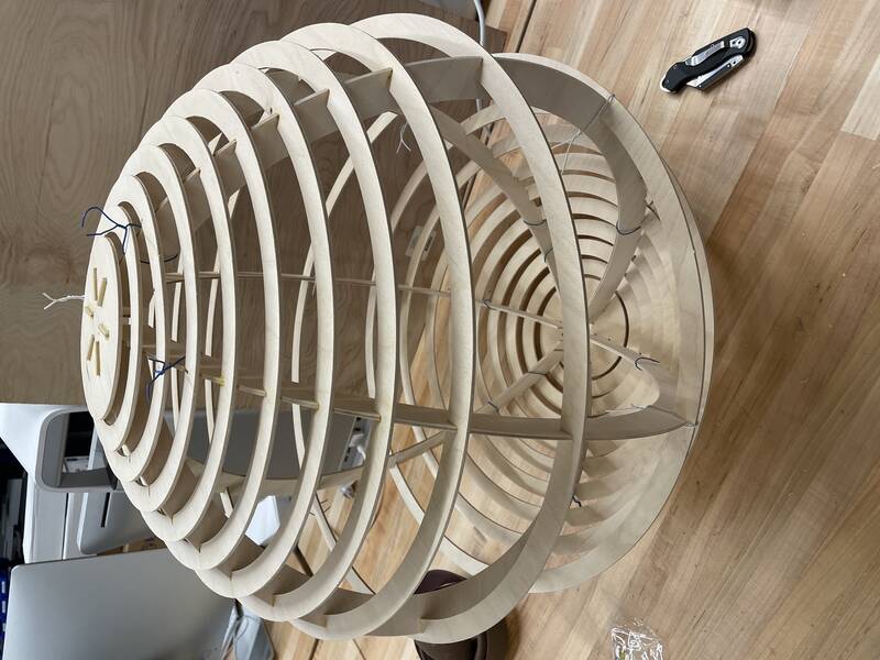
Assembly
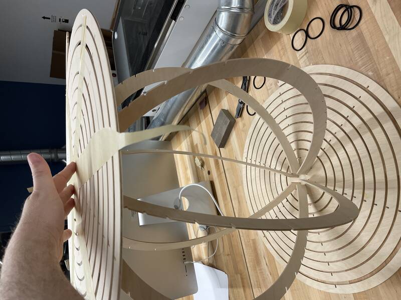
Putting this thing together by myself was a gigantic pain in the ass. The structure is unbelievably floppy until all the slots are locked in place. It really needs eight hands! I managed to make it work by taping the spirals together so they didn't flop around when I didn't want them to, and holding the slot connections together temporarily with wire.Once it's all together, though, it's a lot more rigid and supports its own weight. But it's not as strong as I'd hoped. Because I had to use thinner material than planned, it doesn't have quite enough tensegrity to hold itself together securely. The slot tolerance is still just a bit too sloppy, and I left too much clearance for cutting bit radius at the back of the slots. So I had to use glue.
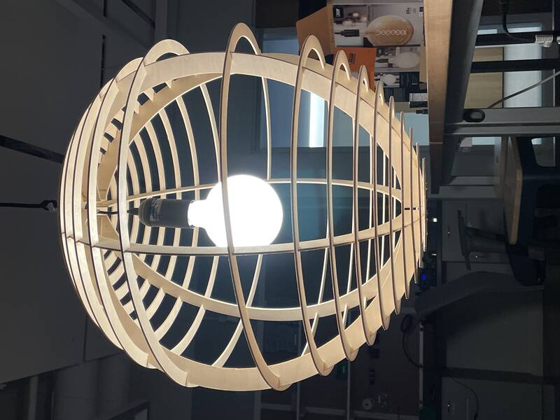
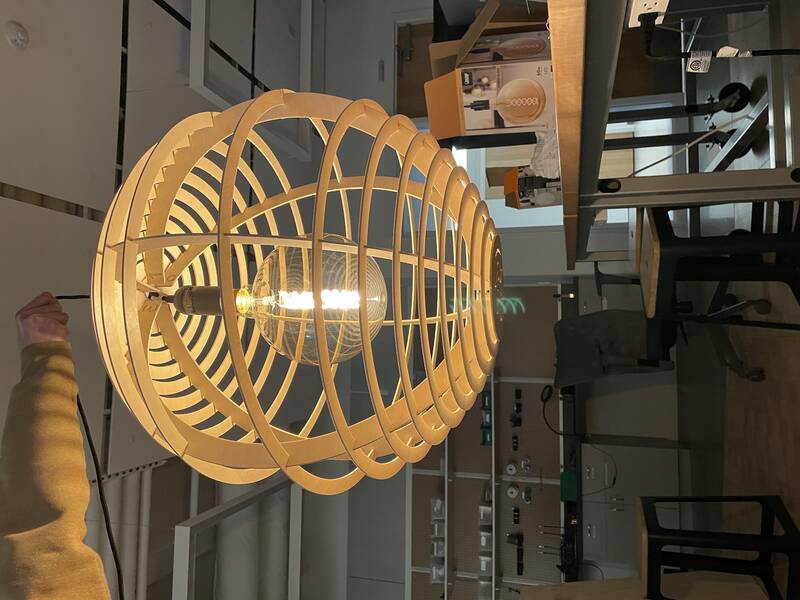
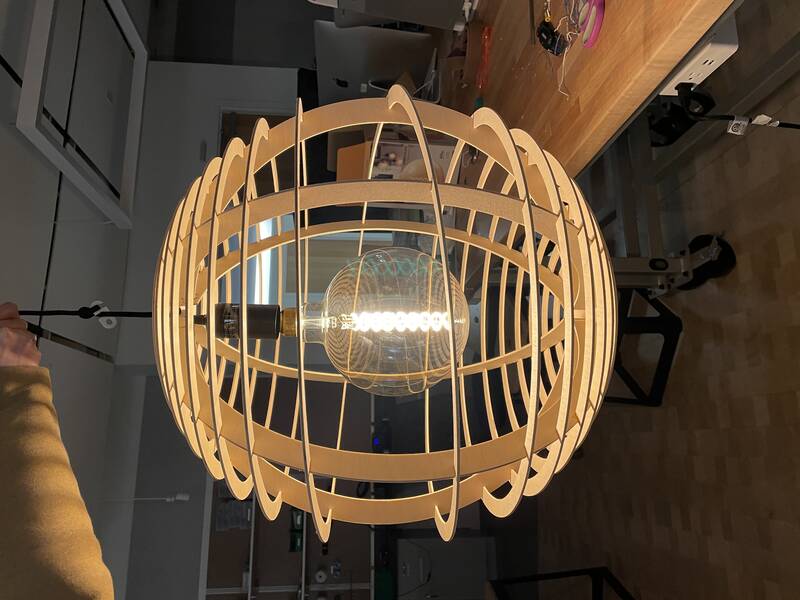
Finished!
While the glue dried, I took a trip to the hardware store and got a basic pendant lamp kit and a globe light bulb. I had intended to buy a simple 4-inch spherical bulb, but while I was there I saw an 8-inch clear globe with a double-helix spiral LED filament, which I just had to have even though it was super expensive. I had to disassemble the light fixture to get its cord to pass through the mounting hole in the top of the sphere, and I had to unglue part of the spiral to get the gigantic bulb inside, but I think the results speak for themselves!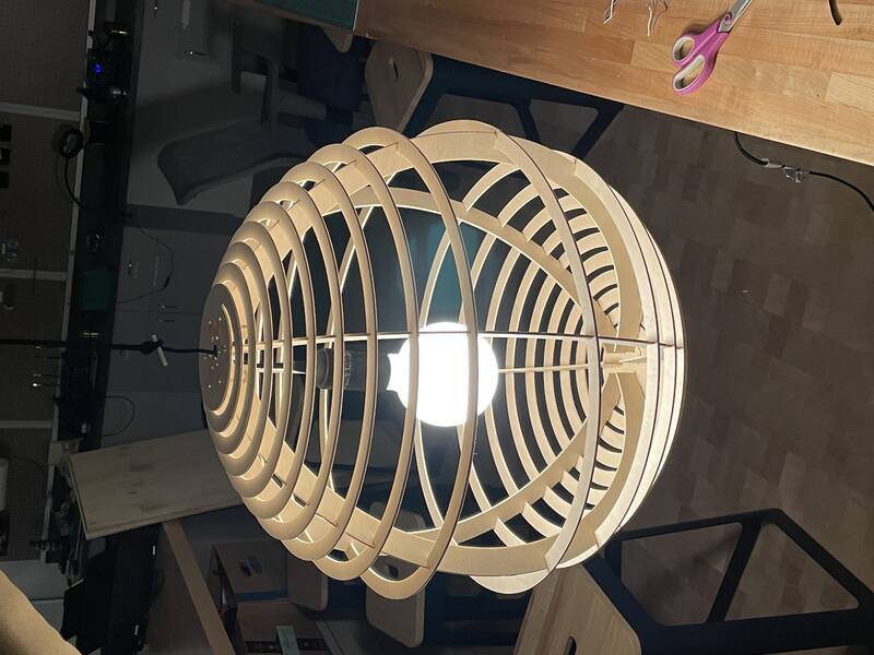
Conclusion
I spent waaay too much time on this one, and I slammed head-first into the limits of OnShape this week, but after much frustration I'm pretty happy with the result. I'm not 100% happy with the spacing of the spirals: there's too few turns near the equator, but that's dictated by the geometry of the flat sheet and can't really be fixed. If I were to do another version, I'd tighten up the tolerances even more and use 3/16" wood instead of 1/8 for more rigidity. Though honestly this thing is too huge to be useful as a lamp in most homes: if it wasn't Make Something Big with CNC week, this design might work better as a desk lamp, made of very thin veneer and cut on a laser cutter.
Design Files
- helix-lamp.zip: Zipped STEP file CAD design.
- helix-lamp-sheet-1-p125.svg: Cutting path for sheet 2
- helix-lamp-sheet-1-p125.svg: Cutting path for sheet 3
- helix-lamp-sheet-1-p125.svg: Cutting path for sheet 1