Design and Manufacturing Process
Final Questions
Answers to many of these questions are copied from elsewhere on the site, see Week 16 Applications and Implications.What does it do?
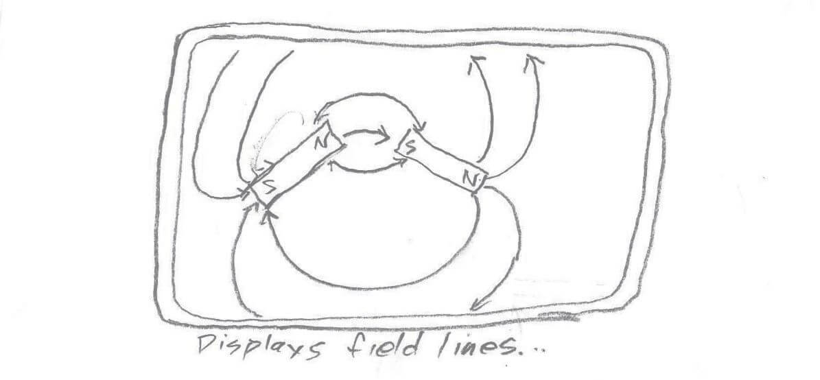
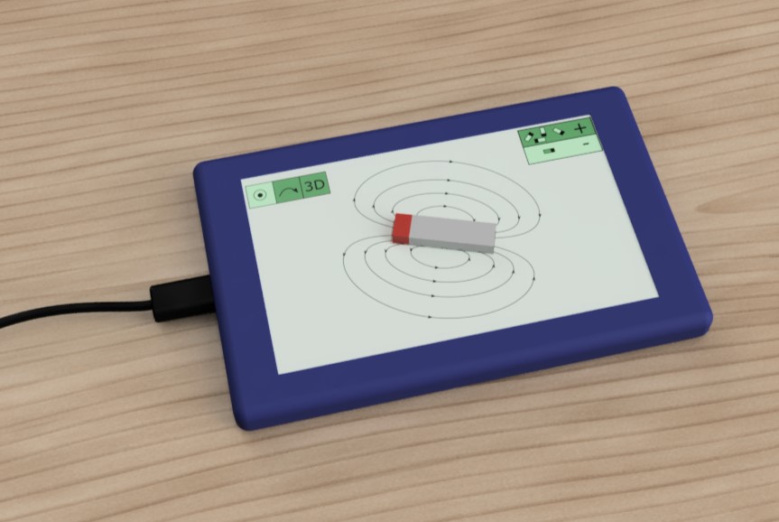
This device lets the user see invisible magnetic fields. It uses a large array of magnetic field sensors to map out the strength and direction of magnetic fields passing through it. It has a screen to draw and display magnetic field lines and vectors. It is able to sense strong permanent magnets, as well as the weak fields from single current-carrying wires, and the Earth's magnetic field.Who's done what beforehand?
There are some old-school non-electronic ways of visualizing magnetic fields using iron filings or small compasses, and some research groups have developed arrays of magnetic sensors, but I have not found any commercial product similar to my "field camera". See Week 16 for a full review of prior art.What did you design?
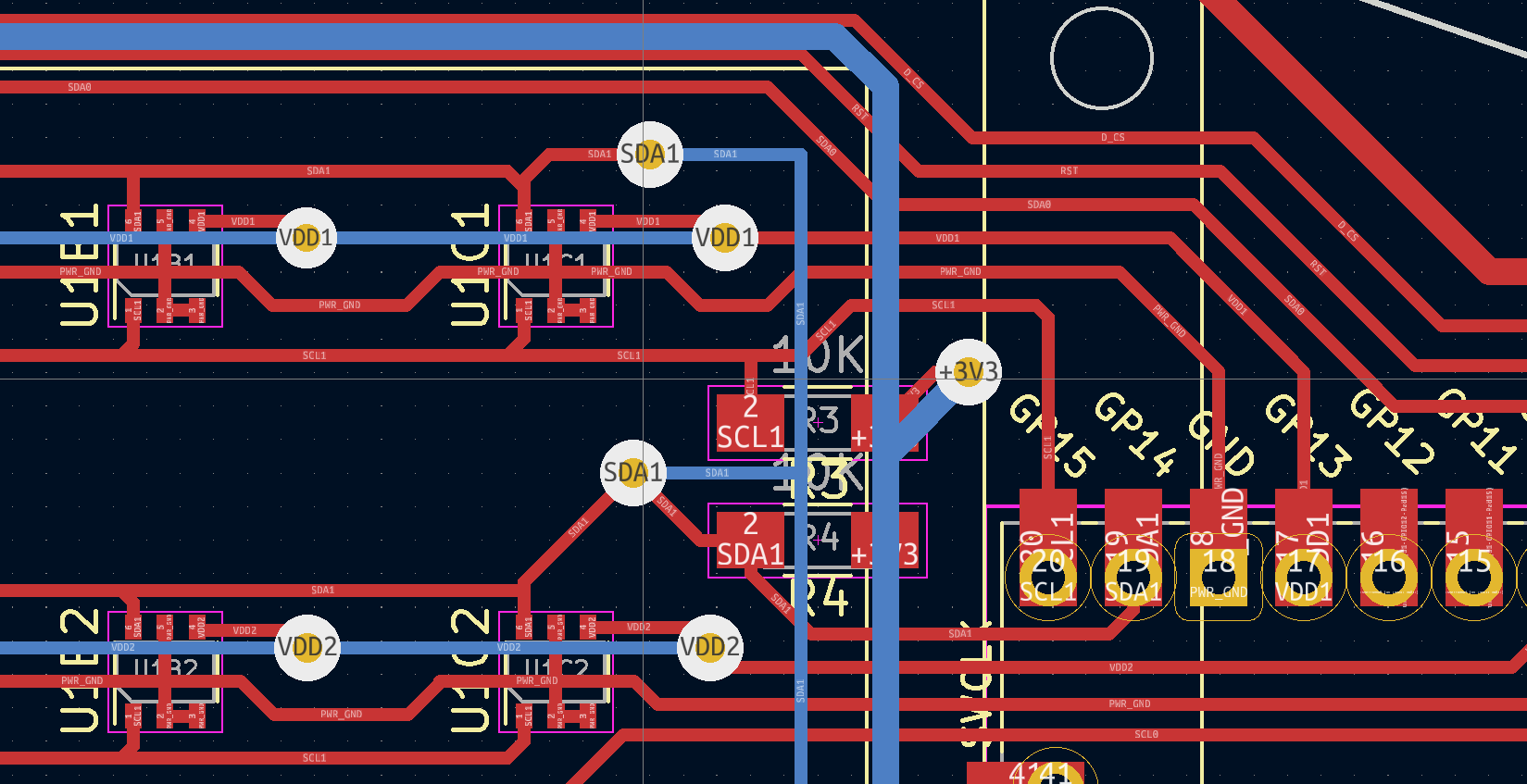
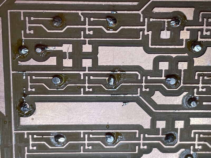
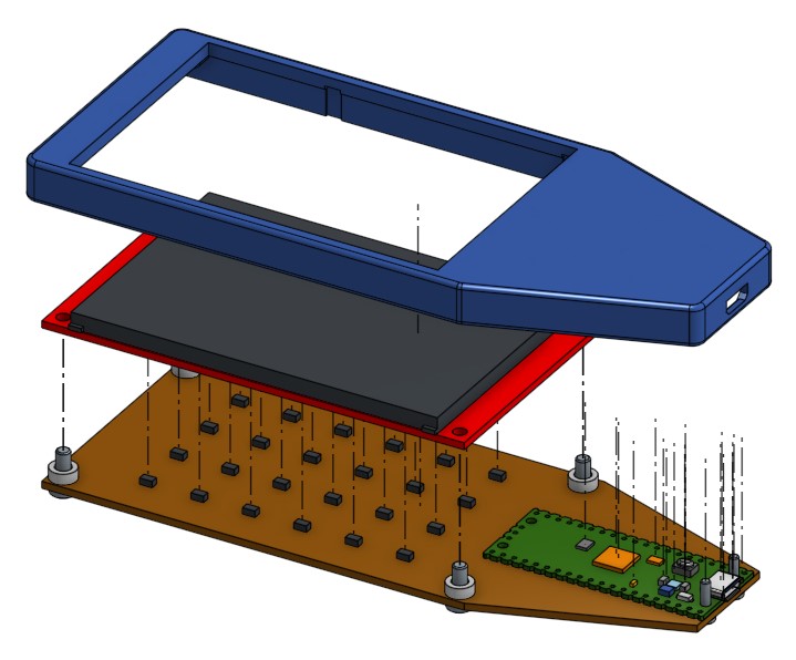
- A PCB carrying an array of 24 3-axis Hall-effect magnetometers
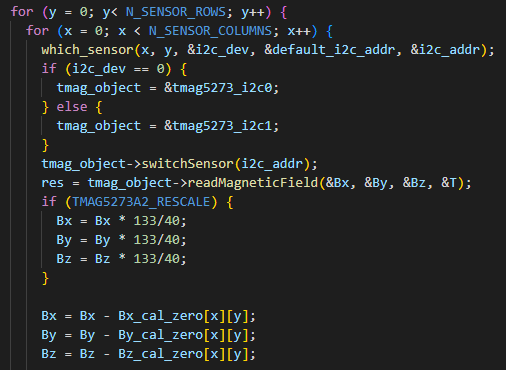
- A system for interfacing large numbers of sensors to a single microcontroller, using I2C address reprogramming
- A system for drawing vector field arrows on an LCD screen
- A touchscreen GUI to change settings for the field camera
- A program to assist in calibrating and zeroing the grid of sensors
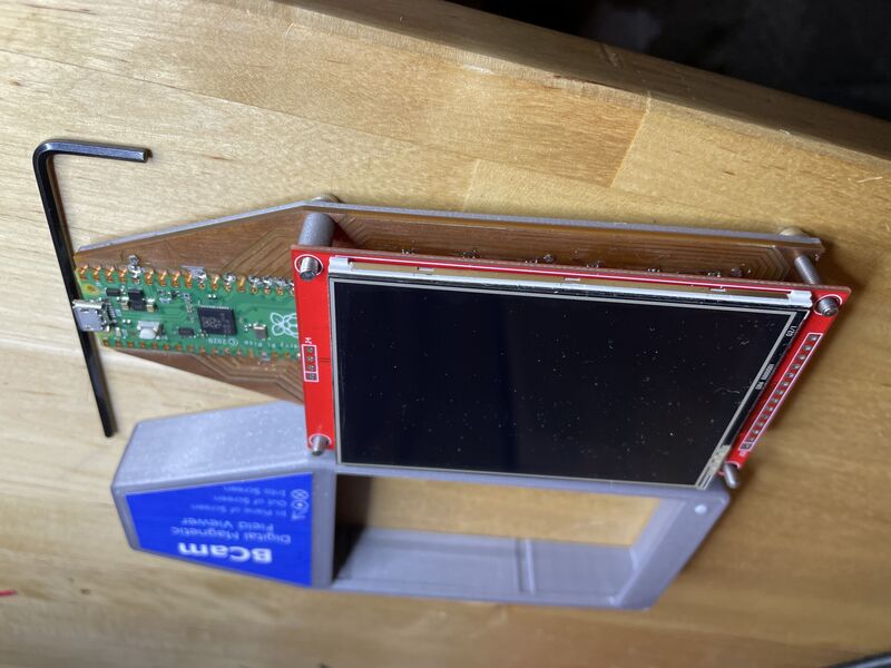
- A 3-d printed plastic case to hold the project
What materials and components were used?
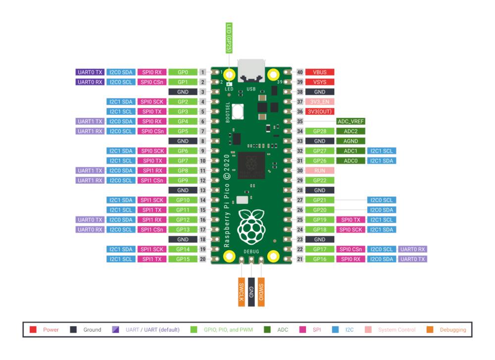
Full details are throughout this document, and a bill of materials is linked here, but the primary components were the TMAG5273 3-axis Hall Effect magnetic field sensor, the Raspberry Pi Pico RP2040 microcontroller module, and the ILI9488 touchscreen TFT LCD screen. 3-d printing, printable vinyl stickers, and a few screws rounded out the project.Where did they come from?
See Bill of MaterialsHow much did they cost?
See Bill of Materials. Total cost is about $65.What parts and systems were made?
All of the parts and systems I designed (listed above) were successfully built, assembled, and tested.What processes were used?
- 2D design: nameplate sticker, presentation poster
- 3D design: full project 3-d design, including case and other parts
- additive manufacturing: 3-d printing of case and other parts
- subtractive manufacturing: PCB milling, milling alignment jig for double-sided PCB
- electronics design and production: double-sided PCB design, including vias
- embedded microcontroller interfacing and programming: Code to read sensors, display results on LCD, handle touchscreen interface, report data to serial port
- system integration and packaging: Unified design with clean case, all pieces securely screwed together, no loose wires, sexy label
What questions were answered?
I successfully tackled the following big questions that I didn't have answers for at the start of the project:- Will the device be sensitive enough to detect tiny magnetic fields?
- Can I build a touchscreen GUI from scratch?
- How do I interface with 24 different I2C sensors?
- Can I master double-sided PCB design?
What worked? What didn't?
Everything worked, the project was a huge success. I did not have time to complete the later "spiral design" goals, in particular I had hoped to create a camera that portrays the 3-d structure of magnetic fields from a distance. This can be done with the machine I have built, it's just a matter of writing some extremely gnarly software. I intend to continue working on this in the future.How was it evaluated?
My primary evaluation criteria were:- Does it successfully measure Earth's magnetic field, and the field from a long straight wire carry a few amps of current? YES
- Does it successfully measure the field from a small rare earth magnet? YES
- Is the visual display informative and helpful to the user? YES
- Does it look cool? HELL YES
What are the implications?
I'm super happy with how this thing came out, and I'm looking forward to showing it to other physics teachers. I plan to show it off within my department, and possibly use it for the Electricity and Magnetism class I'm teaching this fall. I may write up the design and some pedagogical documents like lab handouts, and publish them in a science education journal or present at a conference. I'll be creating a project GitHub that streamlines the project documentation for others to use. It's possible I might be able to commercialize this design, though it will need additional work to get there.Bill of Materials
Design Files
- field-camera.zip - Zipped STEP file of mechanical parts
- kicad/field-camera-sensor-board/ - KICAD circuit project, schematic and board design files
- arduino/field-camera/ - Main Arduino code
- arduino/calibrate_field_camera - Calibration program for magnetometer sensors
- arduino/fieldcam_test_magnetometers - Magnetometer hardware testing sketch
- arduino/JCG_ILI9498_PicoRP2040.h - Setup script for Bodmer TFT eSPI library
- 2d/field-camera-sticker.svg - Logo sticker
