Mechanical Design
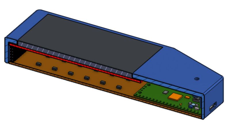
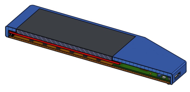
A schematic cross-section through the project is shown below. There are two main goals with the mechanical design. First, get the magnetic field sensors as close to the screen as possible, since the goal is for the screen to show field arrows at the location where the field is sensed. Second, minimize sources of magnetic "contamination". I can't do much about the currents flowing through the circuit board, but I can eliminate all ferromagnetic materials, which tend to trap and amplify magnetic fields, and become magnetized themselves. Towards this end, I used brass screws rather than steel to hold the project together.
There was one really annoying piece of steel that caused trouble: the TFT display has a flash card reader mounted to its underside, very close to the magnetic field sensors. This became magnetized when you brought a magnet near the camera, noticeably messing up the calibration. I carefully desoldered this and removed it.
Thick and Thin
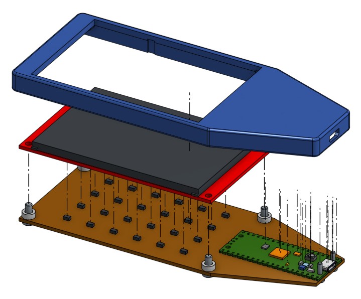
To get the sensors as close to the display as possible, I will solder the TFT display directly to my board. However, there's no going back from that: once done, the display might be almost impossible to remove, so any problems with the board could become unfixable. To mitigate this risk, I first soldered on 0.1" female headers and plugged the TFT display into them. This makes the overall design "fatter", but more repairable.CAD Modeling
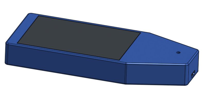
The CAD design for this project was quite straightfoward: all I need is a simple box with an opening for the screen, the USB port, and some screw holes to mount everything together. I did add one handy feature: a small hole in the front of the case: you can insert a paperclip into the hole to press the Raspberry Pi Pico's "Bootsel" button, allowing it to be reprogrammed without removing it from the case.As mentioned above, I created both a "thick" and "thin" versions of the case, to suit the design with and without female headers. The thick version is for prototyping, the thin version will be the final product.

Labels
Finally, I created a label that provides some helpful information on the vector display, and covers the Bootsel reprogramming hole to create a finished look. This was printed using the inkjet-printable vinyl I worked with in Moldmaking and Casting week. This sticker could have been cut with the vinyl cutter but I just used a sharp knife and a straightedge. Subtractive manufacturing!
