  group assignment:
      review the safety data sheets for each of your molding and casting materials,
         then make and compare test casts with each of them
      extra credit: try other molding and casting processes
   individual assignment:
      design a mold around the stock and tooling that you'll be using,
         mill it (rough cut + three-axis finish cut),
         and use it to cast parts
      extra credit: use more then two mold parts
Group Work
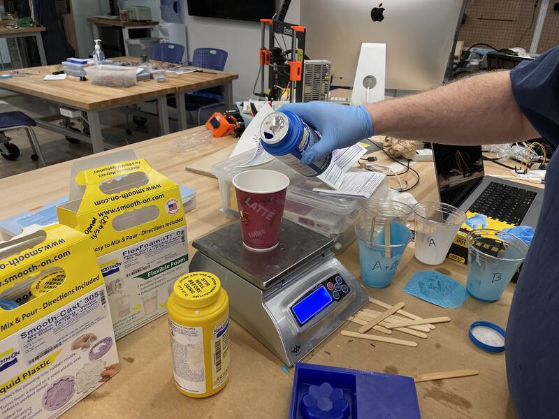
I was away on a secret government mission (really) this week so I ended up doing the group work on my own rather than with the rest of the class.Materials and Safety Data Sheets
| Material | Purpose | Mixing Ratio | Pot Life | Cure Time | OSHA Hazard Classification | Protective Equipment |
|---|---|---|---|---|---|---|
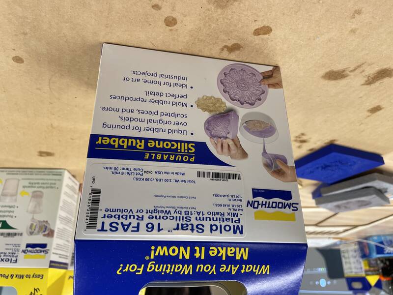
| Smooth-On Mold Star™ 16 FAST | Making flexible silicone molds | 1:1 | 6 min | 30 min | Not hazardous | Gloves, goggles |
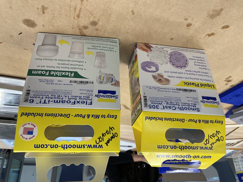
| Smooth-On Smooth Cast 305 | Hard urethane casting | 1:1 by vol | 7 min | 30 min | Skin irritant, allergen, eye irritant, harmful if inhaled, respiratory irritant, possible carcinogen, damage to olfactory organs | Gloves, goggles, good ventilation |
| Smooth-On Flex-Foam It 6 | Urethane foam rubber casting (10:1 expansion) | 1:1 by vol | 35 sec | 2 hours | Skin irritant, allergen, eye irritant, harmful if inhaled, respiratory irritant, possible carcinogen, damage to olfactory organs | Gloves, goggles, good ventilation |
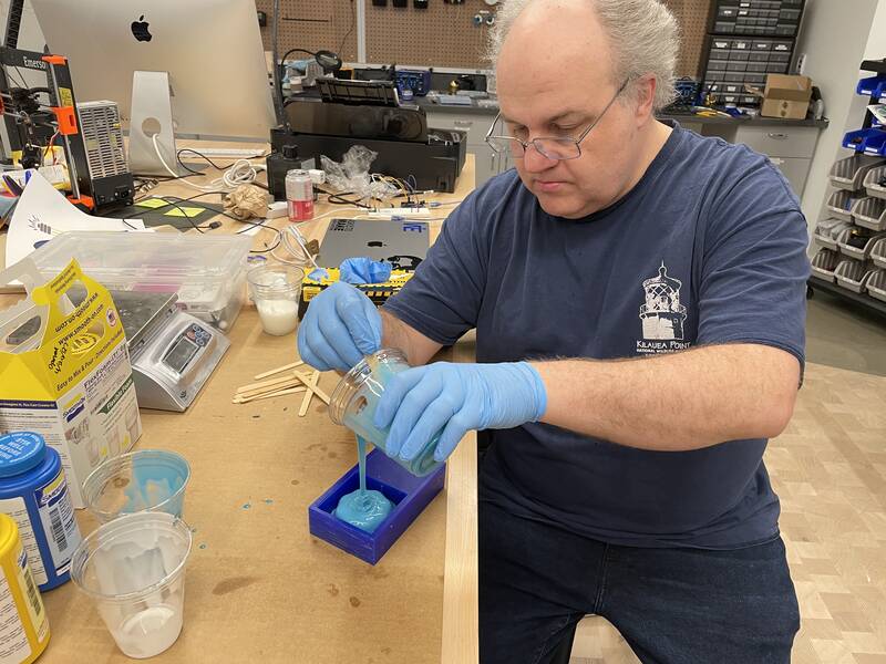
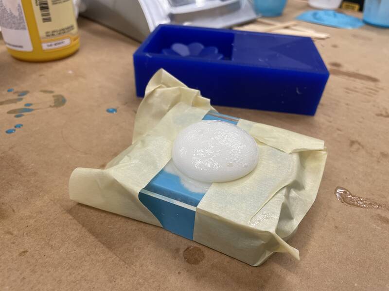
Testing Materials
For my tests, I used a milled form made by students from a previous year to create a silicone mold using the Mold Star 16 silicone, then used that to cast a foam rubber part using the Flex-Foam It urethane material.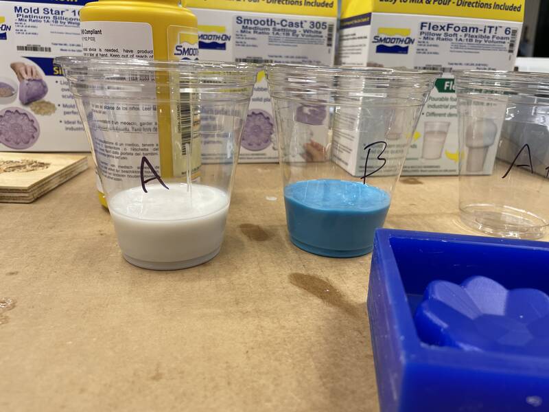

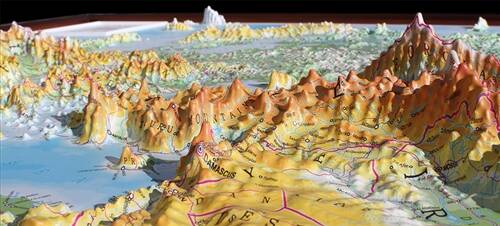
Concept: Custom Raised Relief Topo Maps
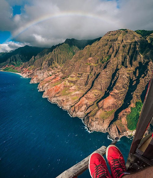
When I was a little kid, back when book stores and map stores were a thing, you could buy raised relief maps, where the printed map was overlain onto a sheet of plastic that had the hills and valleys on it as a 3-d relief texture. They were made by vacuum forming, and you can still buy them, but that's no fun. I want to be able to make DIY custom raised relief maps of anywhere in the world -- or anywhere in the solar system!My test cases for this week will be the Hawaiian island of Kaua'i, where I grew up, and the volcano Olympus Mons on Mars. Kaua'i's mountains are really rugged, which will make for an extreme test of the method: Olympus Mons isn't as complicated, but since it's on a different planet I anticipate that getting topographic data will be harder.
Most Fab Academy students do "wet" casting this week, but I think vacuum forming is a valid technique for this assignment. For starters, Neil mentions it in his notes, and also, I'll have to master most of the skill goals this week (milling a mold, thinking about negatives and positives, draft, and mold release). I will make sure to learn how to do resin casting separately.
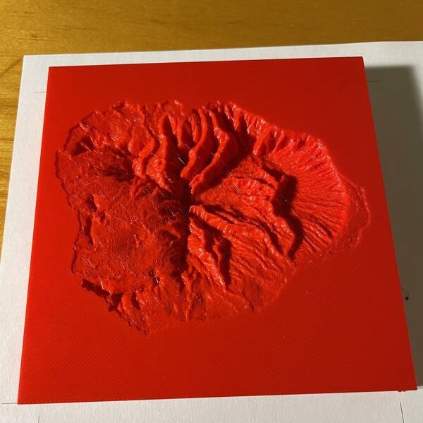
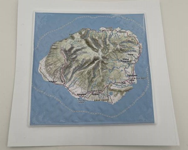
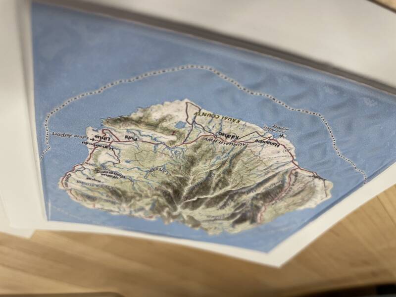
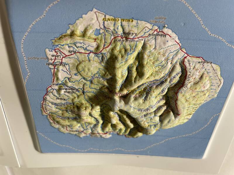
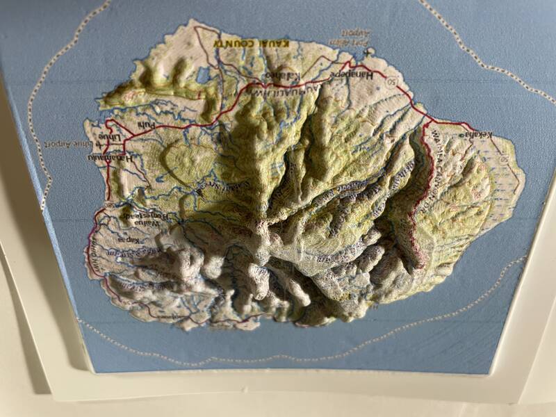
Hero Shots
Before we get into how I made this work, here are some pictures of my final results.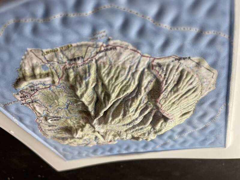
Design Process
The key questions I had to answer to make this work were:- Where can I get topography data, and how can I convert it into a 3-D CAD file?
- How can I color print a 2-d map image onto plastic?
- How can I vacuum form small objects?
- Will the map image distort as the plastic sheet is formed?
- What's the best way to make a mold for this?
Topography Data to CAD
Earth
In 2000, space shuttle Endeavor flew the Shuttle Radar Topography Mission (SRTM), which collected detailed elevation data for almost the entire planet Earth. You can download this data freely, and even better, there are several websites that will automatically use it to generate STL files automatically, most notably Terrain2STL and Map2STL. I tried out both to see how well they worked.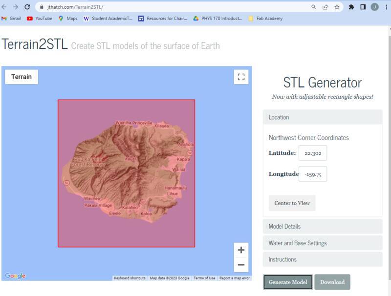
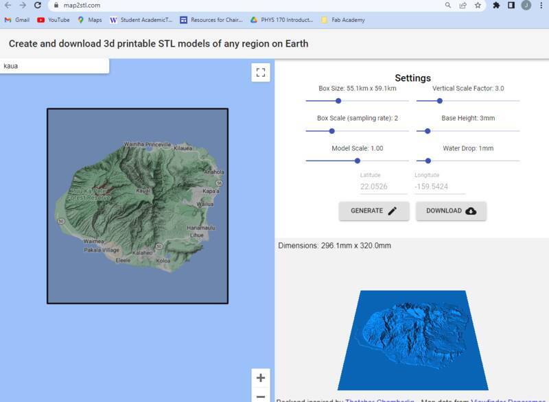
I used the 3d Print Toolbox in Blender to analyze these STLs for trouble, and found that Map2STL generates very bad STLs, with lots of non-manifold surfaces, inverted normals, and flat-out missing faces. Terrain2STL produces good "watertight" objects, and has better detail anyway, so it's the obvious choice.
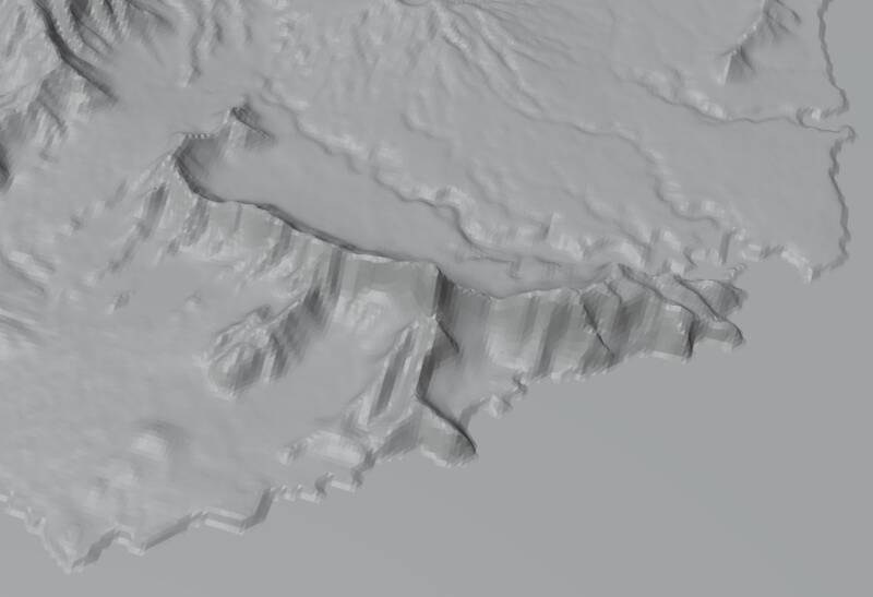
I did a bunch of manual work in Blender to tweak the STLs generated by this site. To get the best surface fidelity and avoid exposing the printed side to the heat lamp, I'll be forming these upside-down, into a negative mold. I also had to adjust dimensions to make sure the mold fit nicely into the vacuforming machine.Mars
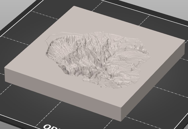
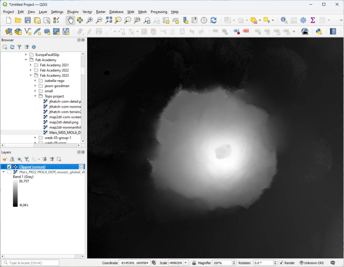
Mars is one of the few planets that we have good topography data for -- in fact, we know Mars's topography better than Earth's! (Mars isn't covered in annoying oceans and trees.) The Mars Orbiter Laser Altimeter (MOLA) instrument mapped the entire planet from 1997-2006. The data is publicly available, but nobody makes a handy website to convert it to STL, so I'll have to do it myself. Here's my process:- Download the Mars MOLA DEM (Digital Elevation Model) in geotiff format.
- Install QGIS, a free Geographical Information System program. Fortunately I have some experience working with GIS, if you're new to this the learning curve is steep.
- Start QGIS and install the "DEMto3D" Plugin, which creates STL files from DEM data.
- Create a new QGIS project.
- In the "Layer / Data Source Manager", add the MOLA DEM data as a data source.
- Zoom and pan so the desired region fills the screen, then choose Raster/Extraction/Clip Raster By Extent. Create a new raster layer with only the data you want to create an STL of.
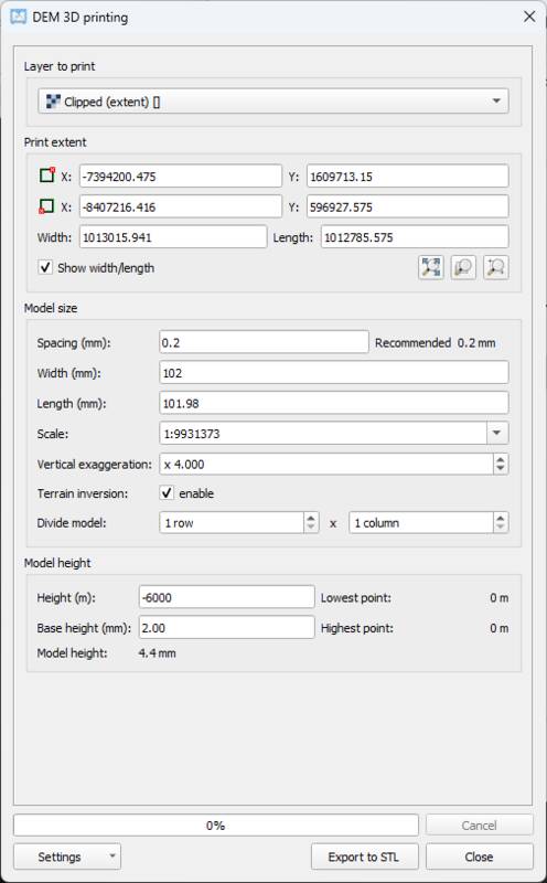
- Choose Raster/DEMto3D/DEM 3D Printing. For the "Extent", choose "Select full extent". Other values should be as shown in the screenshot below. "Height" is the elevation of the lowest point in your model. Select "terrain inversion" to get a negative (mountains are holes), which will be useful when we make a vacuform mold.
- Choose "Export to STL" to create an STL file.
- The DEMto3D plugin is buggy and will give all kinds of errors, but they're mostly harmless.
Color Printing onto Plastic? Printable vinyl!
I want a color image overlaid on the vacu-formed shape. This is a problem, because inkjet ink won't stick to the plastic sheets we use in the vacuformer (I tried!), and you can't run them through a laser printer or they'll melt (I didn't try!). I was afraid I'd have to spend money on dye-sublimation printing or something, so I asked the /r/Printing subreddit if they had any ideas. Someone let me know that printable vinyl sheets are a thing. The intended purpose of these is to print on them, then run them through a vinyl cutter to make custom colored stickers. But vinyl is stretchy, so maybe it'll stay stuck to the styrene as it deforms in the vacuum forming machine. Or maybe not. Maybe the inks will be destroyed by the heat. Maybe everything will catch on fire. Only one way to find out!
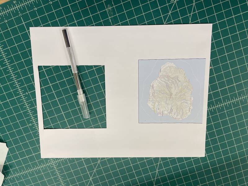
For the Kauai image, I grabbed a screenshot from The National Map. This has more geographic detail than Google Maps and fewer advertisements stuck into the maps, and it also uses the oldschool USGS map style that I loved as a kid. For the Mars image, I used the Viking Color Mosaic. The Viking data is old, there's much better images of Mars available, but it's a classic that's defined what we think Mars looks like and it's plenty high-res enough to work for this project.
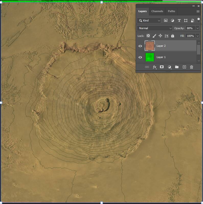
Registration
To make this work, I need the image on the printed vinyl sticker to be perfectly aligned with the vacuum forming mold. This wasn't easy. For the Earth data, I loaded a screenshot of the mold STL into Photoshop, threw the National Map image on top, and scaled and moved it so they matched. For the Mars data, I tried to "georegister" the Viking data onto the MOLA data so I could add topo lines to the image. This was a mistake, QGIS is annoying, I should have just used Photoshop.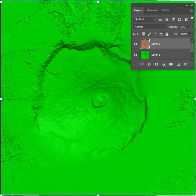
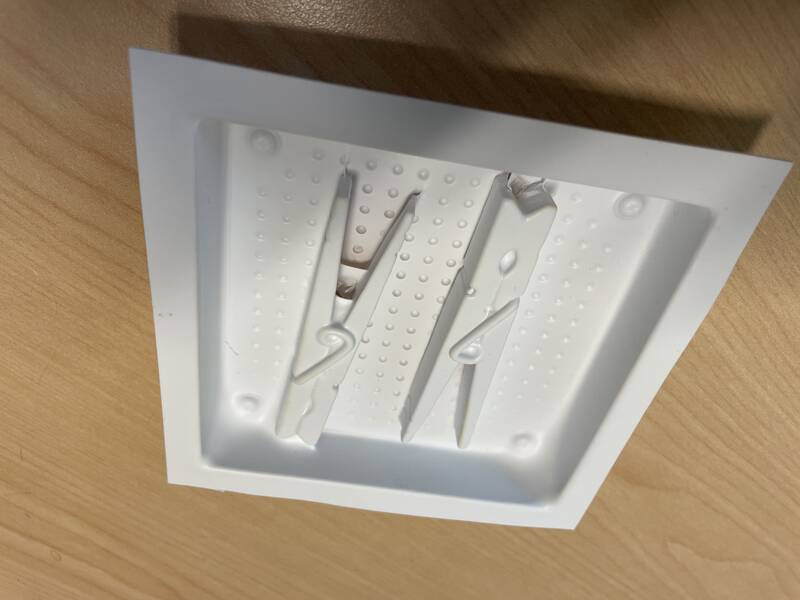
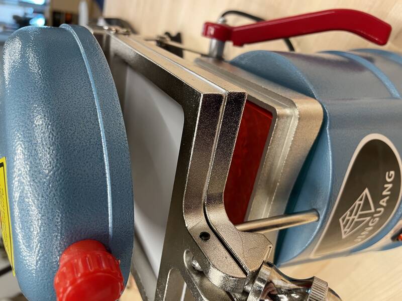
A Tiny Vacuformer
Our college has a vacuum forming machine, but it's huge, like 15" x 24" or so, and we don't have much plastic for it. One drawback to vacuum forming technology is you need to use a whole sheet of plastic, you can't cut it down. To make a big map I'd need a big mold, which will take a long time to make, and I wanted to do a quick proof-of-concept first.
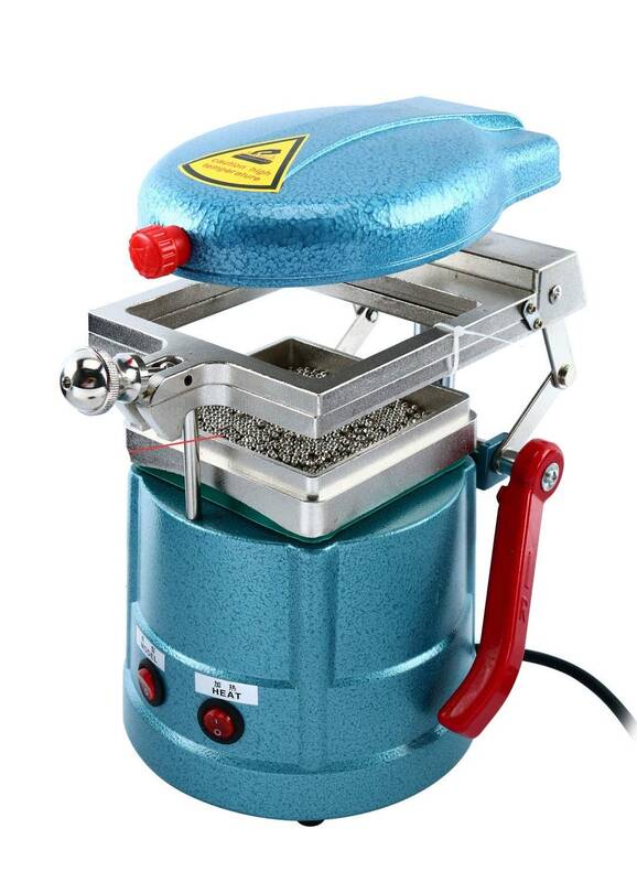
I was looking into the logistics of getting ours up and running, when I saw this video by Mythbuster and maker Adam Savage. It's a tiny vacuum forming machine with a 4" x 4" square bed, and it costs like $120 on Amazon! Apparently it's intended for making dental splints, whatever those are. So anyway I talked our lab manager into buying one. I mean look at it, it's adorable! And it has no instructions and the buttons are printed in Chinese with a label maker!
Anyway we bought one and it works great. The bed size is pretty limiting, but it's super fun to use and at $120, you can't beat the price.
3-d Printed Molds
To fulfill the week's assignment requirements, I need to use a CNC machine to mill a mold. But before I go to the trouble to set all that up, I thought I'd do a test with a 3-d printed mold to see if it would work.
There is an obvious problem here: PLA plastic gets soft at about the same temperature as styrene, so probably this is going to destroy the mold. But I had such good luck with using PLA in high-temperature settings in Week 03 that I thought I'd give it a go.
Manufacturing steps:
- Print out image onto vinyl using an inkjet printer.
- 3-D print terrain mold.
- Cut out image from vinyl sheet.
- Cut styrene sheet to fit vacuforming machine.
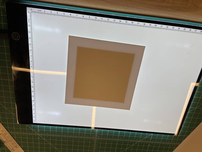
- Transfer vinyl image onto styrene sheet using transfer tape. Get it exactly centered.
- Mark the corners of the vinyl image on the back side of the sheet. The light box I got for Week 03 came in handy for this.
- Put terrain mold into the vacuformer and center it.
- Put styrene sheet into the vacuformer and center it using the corner dots marked earlier.
- Turn on vacuformer heater. Heat styrene until it starts to sag. (It will sag less than usual because it's got a vinyl sticker holding it back.)
- Turn off heat, turn on vacuum, and drop the plastic onto the mold.
- Pray to the Fab Academy gods for 10 seconds, then turn off vacuum and remove the part.
Results
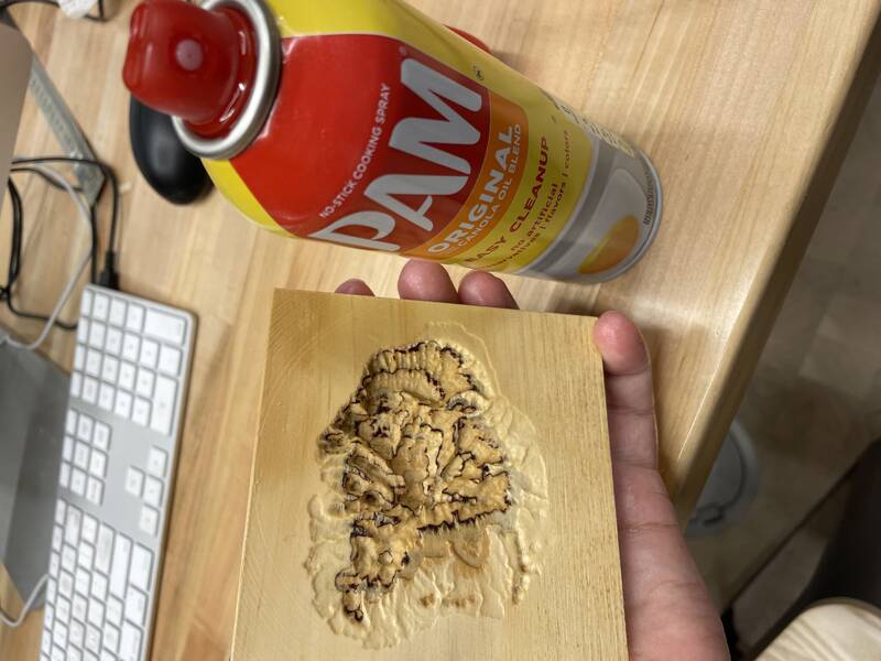
My first run was a disaster, for one simple reason: I didn't use mold release. The hot vinyl welded itself onto the PLA mold, and I couldn't remove the part without destroying it.
For my second attempt, I used nonstick cooking spray (the first thing I found lying around in the shop), and the results were spectacular! The vinyl welded itself permanently to the styrene and conformed perfectly to the mold, and didn't lose its ink. I got the registration almost perfect, and the lettering is clear and readable.
As expected, the mold was damaged from the heat. It got some ink permanently bonded to it from the failed first attempt, and the second successful attempt softened the surface, allowing the gyroid infill pattern inside the 3-d print to show through. The infill pattern made a quilted design on the ocean around the island, which is pretty but not what I want.
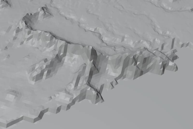
Olympus Mons worked great too, but the mold was also damaged from the heat. Less badly but still noticeable. I also had trouble preventing the sheet from warping when I pulled it out of the mold. But it really captured the steep cliffs that ring the base of the mountain, and the caldera and impact craters on top!
CNC milled mold
To make this work, I need a mold that can survive higher temperatures. To satisfy the Fab Academy requirements, I need to CNC mill a mold. So those two goals work together! Our instructor showed us how to use machinable wax, but that won't work, because wax melts. The right material for my application is wood: easy to mill, temperature-resistant, strong.
So I set out to create a CNC-milled Kauai mold. (I'm not going to bother re-doing Mars.) Because I'm a glutton for punishment, I tried to do it on a Sainsmart Genmitsu 3013 ProVer, rather than a sturdier and bigger CNC mill. This was not the best plan. Anyway, here are my steps:
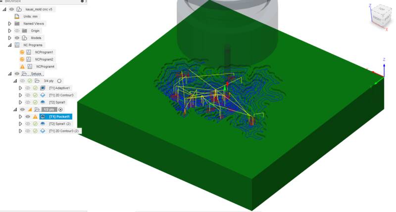
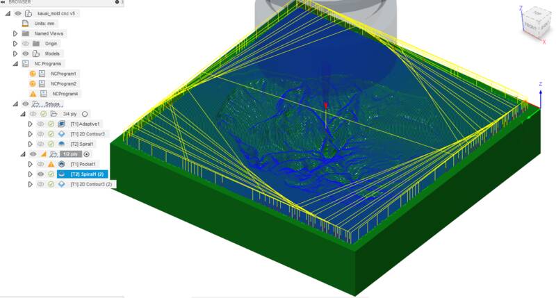
- Import the STL file into Fusion 360.
- In the Manufacturing workspace, create a new "Setup". Set the stock to be 1/2" thick, and even with the top surface of the model. Set the workspace origin to the bottom left corner of the model, Z=0 at the top of the model.
- The first operation is a "Pocket" to make a rough hole. I used a 1/8" flat bottomed endmill, 10,000 RPM, feedrate 400 mm/min, Conventional milling, maximum stepdown 1 mm, stock to leave 0.2 mm axial and radial, 10 degree helix ramp-down. 400 mm/min was too fast, I had to slow it down while cutting.
- The second operation is a "Spiral" to finish the topography, and hopefully create a nice spiral pattern of grooves. I used a 2 mm ball-nosed endmill, 10,000 RPM, feedrate 400 mm/min, stepover 0.5 mm.
- The final operation is a "Contour" to cut out the part from the material. I went back to the 1/8" flat bottomed endmill, 10,000 RPM, feedrate 400 mm/min, 1 mm maximum stepdown, no lead-in, ramp angle 15 degrees, and I added tabs 2 mm high by 1/8" wide every 35 mm at the bottom.
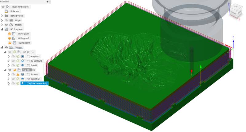
- Simulate the toolpaths to make sure there are no nasty problems.
- Post-process the toolpaths to generate Gcode, using the "Grbl/grbl" postprocessor.
- Load the first toolpath into Candle, the CNC control software recommended for the Genmitsu.
- Load the wood into the bed. I used clamps to hold it down.
- Set the XY-zero and Z-zero positions (bottom left corner of the wood, just clear of the clamp, Z=0 at the top of the wood.)
- Open the "Pocket" Gcode file, and make sure everything looks good.
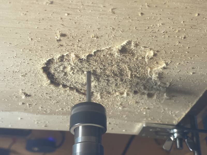
- Send! And pray. I found the Genmitsu really struggled with this: there was a ton of chatter and wobble, sometimes you could see the cutting head vibrating. Slowing the feedrate didn't help. The best approach seems to be shallow, fast cuts. Still, I ended up watching carefully and slowing down the feed rate in Candle when things looked dicey.
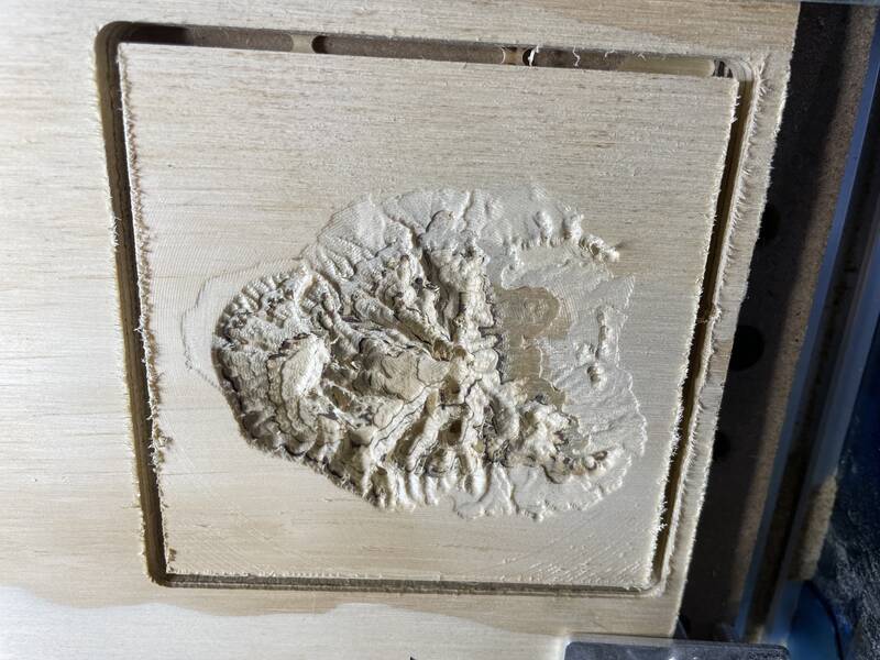
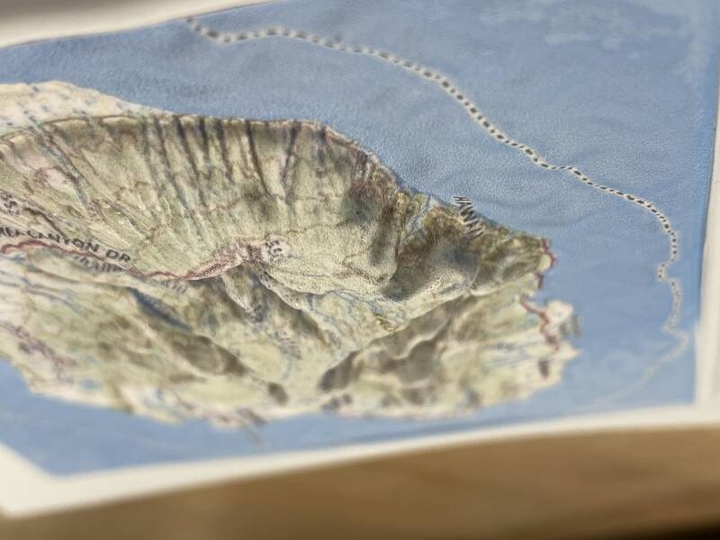
CNC mold results
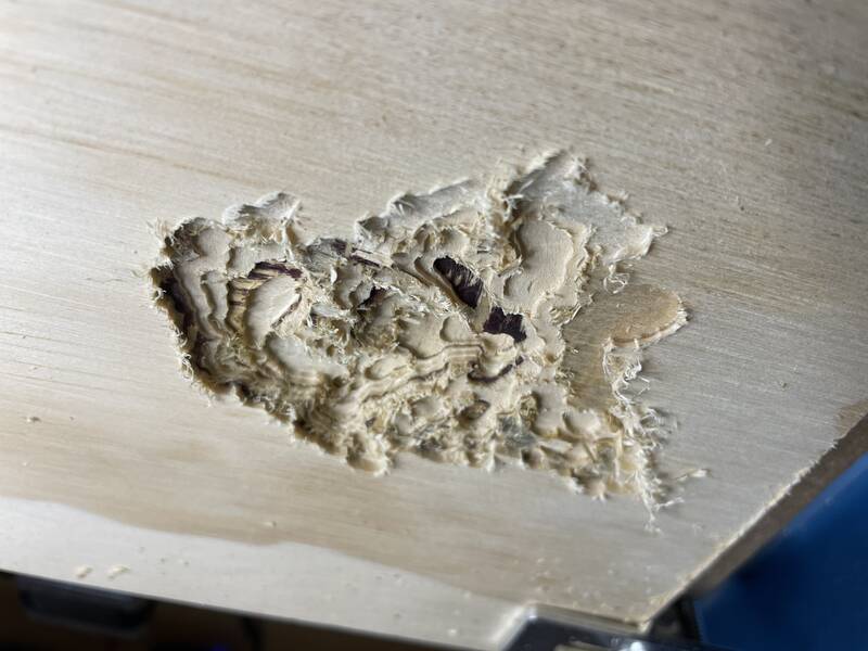
As expected, the wooden CNC milled mold stood up to the heat just fine, and it was also easier to release the part from the mold. The downside is that the 2-mm cutting tool can't come close to the resolution and detail you get from the 0.4-mm 3-d printer nozzle.
Also, the wooden mold is a little less permeable to air than the 3-d print, so the vacuum wasn't always able to pull the plastic deep into the (negative) mountains, causing smooth and rounded topography. Using high heat helped, and drilling a tiny hole partway through the mold at the peak of the highest mountain also helped.
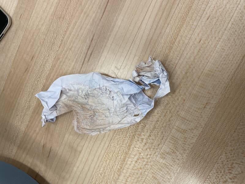
Another problem I faced was that with deep and steep extrusions stretched the vinyl sticker enough to crack the ink layer, causing muted and blurry colors and a somewhat crackly appearance. If I'd chosen anywhere less rugged than Kaua'i, this wouldn't be a problem.
ABS mold
I also tried making a mold out of 3-D printed ABS. This has a higher plastic transition temperature than PLA, so I thought it might stand up to the heat better. Didn't work. The styrene is just too hot, the results were pretty much the same as with PLA.Rubber Kauai
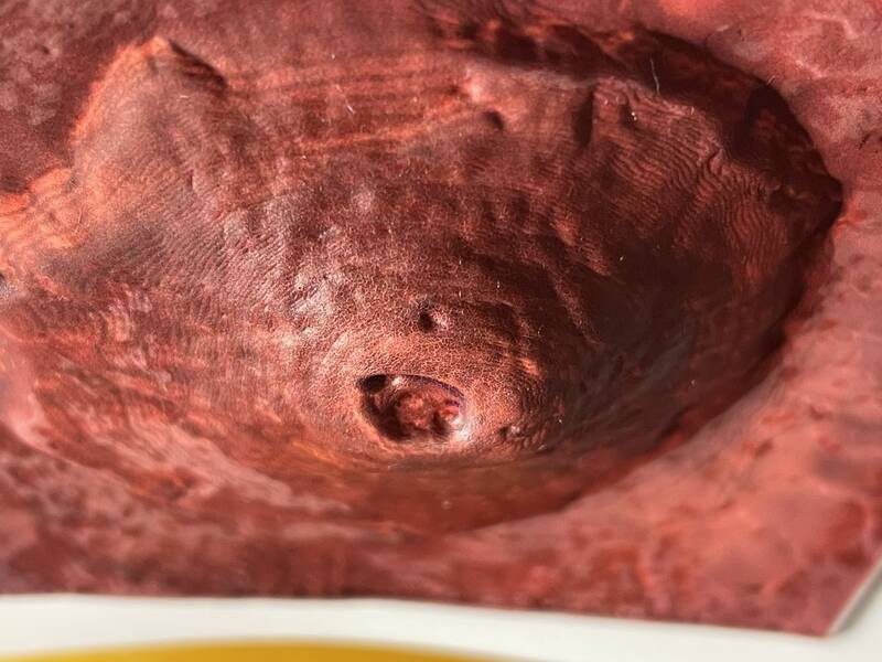
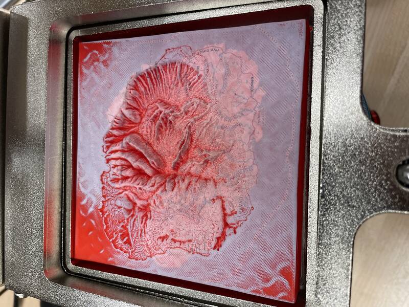
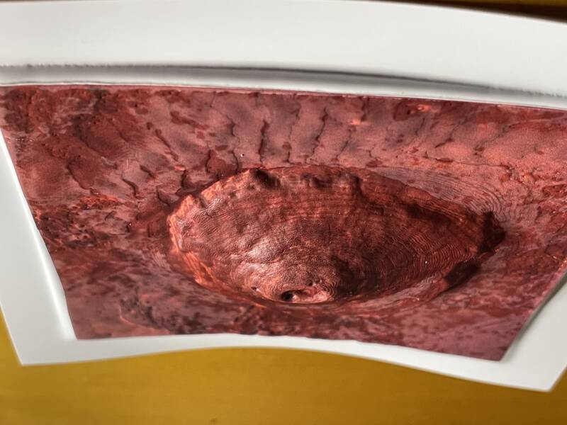
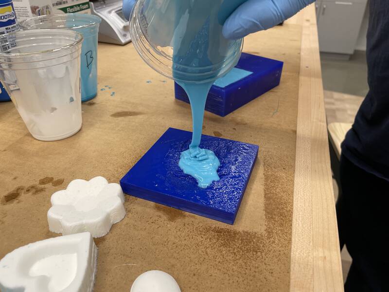
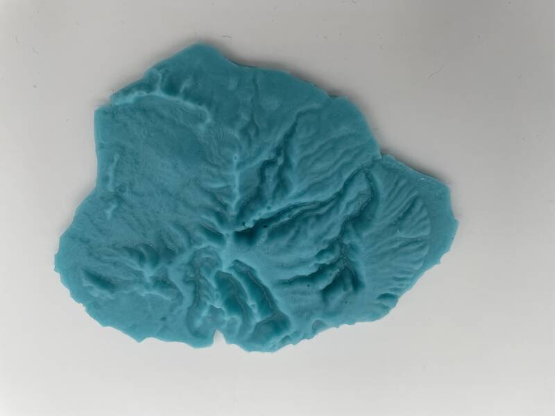
For fun, I tried to use the casting materials with my Kauai molds. I took some leftover Mold-Star 16 Fast silicone moldmaking material and poured it into the 3-d printed ABS mold I made in the previous stage. I sprayed the 3-d print with Pam cooking spray on the theory that I might need a release agent.The results were technically excellent, except that it turned out the mold release wasn't necessary, and kind of a bad idea. The cooking spray dissolved into the surface of the silicone, creating a surface that was slightly tacky even after being cured and washed. Aesthetically, though, the result was absolutely revolting. When molded in silicone, the organic landscape of Kauai looks disturbingly like scarred or rotting flesh.
Next Steps
The biggest lesson I learned this week is the power of moldmaking and casting to allow you to mass-produce a whole lot of mistakes in a very short amount of time. I have half a dozen almost-good-enough parts, but nothing I'm so happy with that I'd be willing to give them away as gifts to family.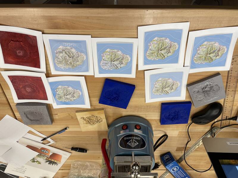
- Make a wooden mold with good-quality wood and a 1-mm ball-end cutter on the large Axiom milling machine.
- Drill a few tiny vent holes in from the back that stop just short of the finished surface of the mold.
- Use a slightly thinner styrene sheet that can stretch more easily.
- Maybe try a positive mold?
- Do the Grand Canyon and Valles Marineris!