      group assignment:
      characterize your lasercutter's focus, power, speed, rate,
         kerf, joint clearance and types
   individual assignment:
      cut something on the vinylcutter
      design, lasercut, and document a parametric construction kit,
         accounting for the lasercutter kerf,
         which can be assembled in multiple ways,
         and for extra credit include elements that aren't flat
My plan is to go all in on "including elements that aren't flat", by figuring out the sheet metal tool in OnShape and creating a construction set made out of bent pieces of clear acrylic. Major tasks for this week:
- Group Lab work: characterize laser cutter, learn about vinyl cutter
- Learn the Sheet Metal tools in OnShape
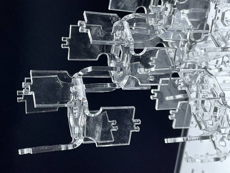
- Design a a bent acrylic sculptural component
- Assemble acrylic sculptural pieces using Assembly in OnShape
- Create a rendering of what the final object should look like in Fusion 360
- Create and 3-d print "bending jigs" to help shape the acrylic parts
- Cut out acrylic parts, learn how to use heat to bend them
- Mass produce parts and assemble.
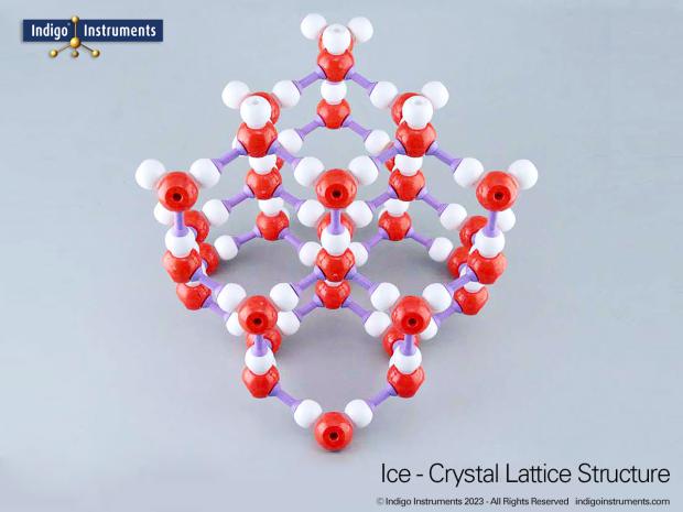
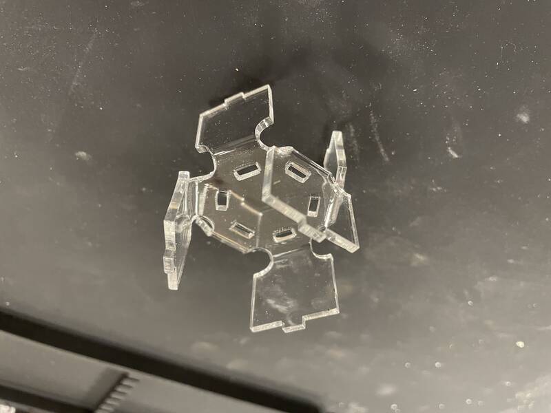
Parametric Construction Kit: "Ice Ih"
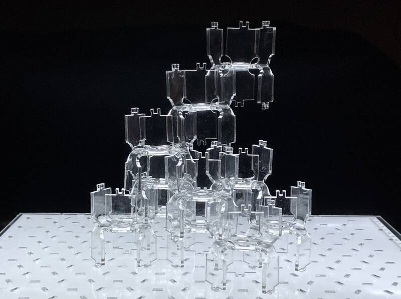
The shape and connection pattern is intended to be reminiscent of the crystal structure of ice, which forms hexagonal crystals due to the hexagonal patterns of hydrogen bonds between the water molecules.
Parametric Design
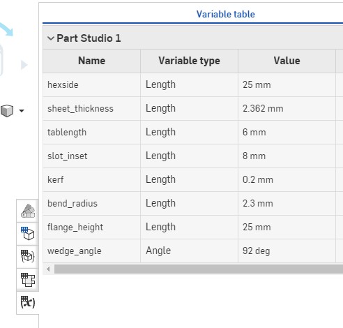
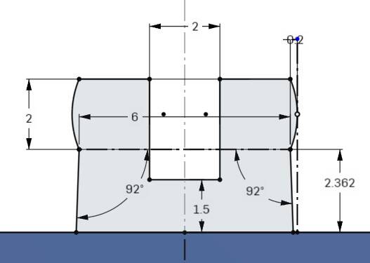
Probably the most important parameter is the "kerf", which will be fine-tuned to ensure a good fit between parts. I didn't account for kerf in every part of the design, only when parts needed to fit together very closely. In practice I made a wild guess at this in my design (0.2 mm), that turned out to be very accurate!
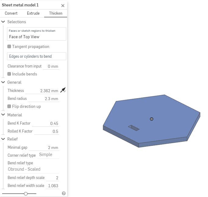
While I didn't need to vary kerf as a parameter, parametric design came in very handy when I realized we didn't have any clear acrylic with the 1/8" thickness I had assumed in my design, and I had to change the design to accommodate .093" (2.36 mm) material. In theory, changing one number should re-build the entire design. In practice, I found the sheet metal tool didn't interact well with rotational patterns, so I had to re-do a few of the design steps by hand. But it sure saved a ton of time overall!
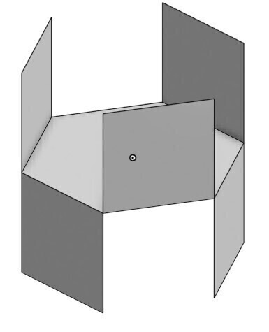
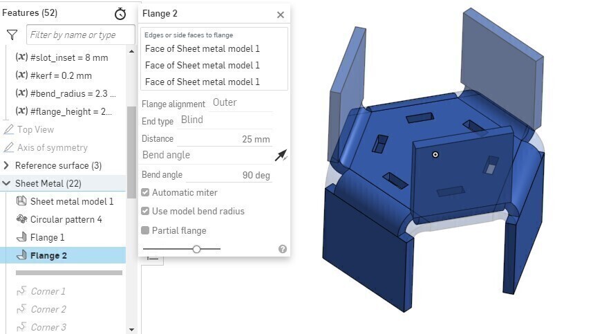
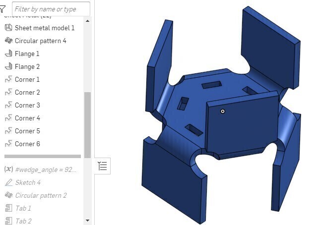
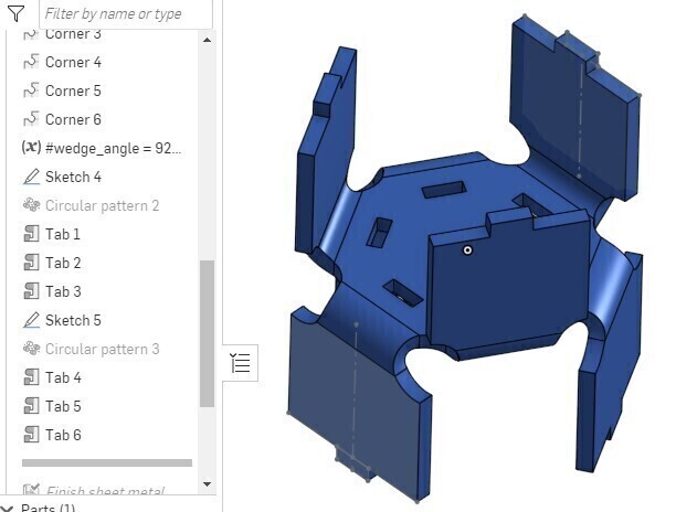
OnShape and Sheet Metal
To begin, I worked through OnShape's simulaneous sheet metal tutorial until I got good enough to work on my own.Here are the steps for creating the crystal hex form:
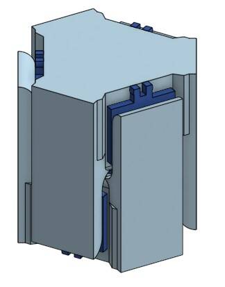
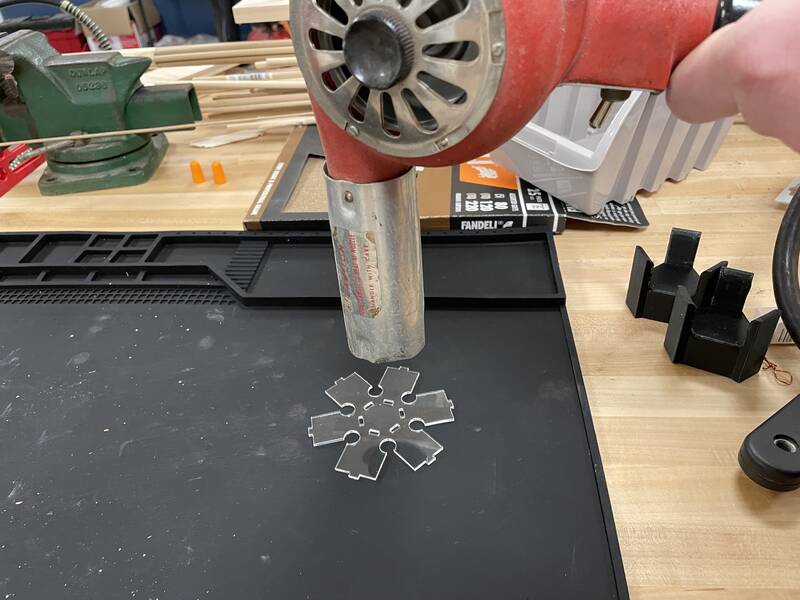
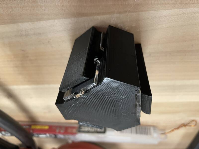
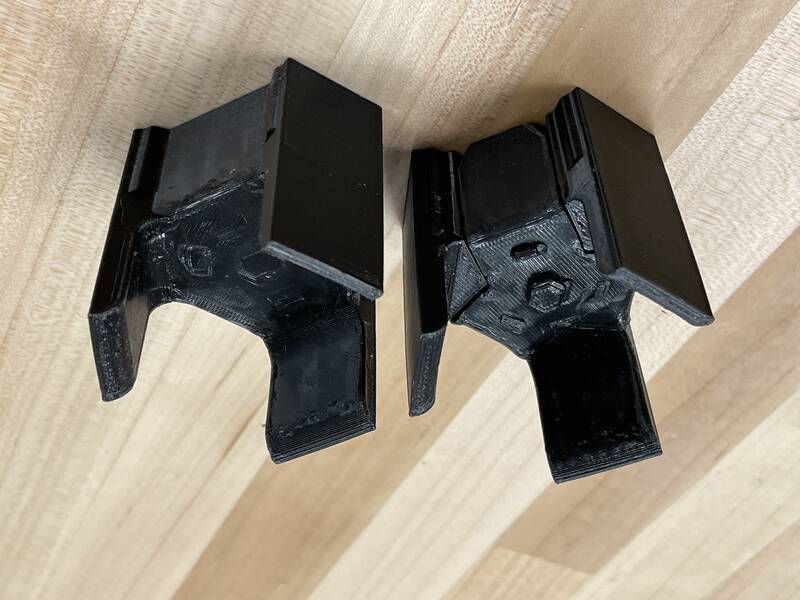
Bending Jigs
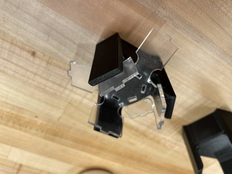
Once the pieces are cut out with a laser cutter, I will heat them up until the acrylic is soft and then bend them. If they are to fit together properly, all the bends in all the parts need to be as identical as possible. To make that easier, I created two identical 3-d printed "bending jigs". I will place the acrylic between the jigs, press them into each other so they interlock, forming the final shape.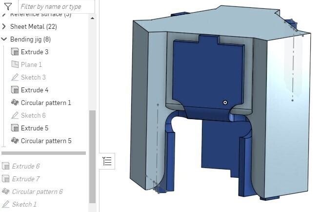
One tricky problem is the glass transition temperature of the plastics. This is the temperature at which they start to become flexible. PMMA (Acrylic) has a higher glass transition temperature than PLA 3-d printing plastic, so the bending jigs will become soft at a lower temperature than the acrylic! My plan for solving that is to heat only the acrylic, and hope it doesn't have enough thermal mass to soften the PLA before it cools off.
The design process for the bending jigs was pretty straightforward: I projected parts of the folded crystal hex piece into sketches, and then extrude them to form the final shape.
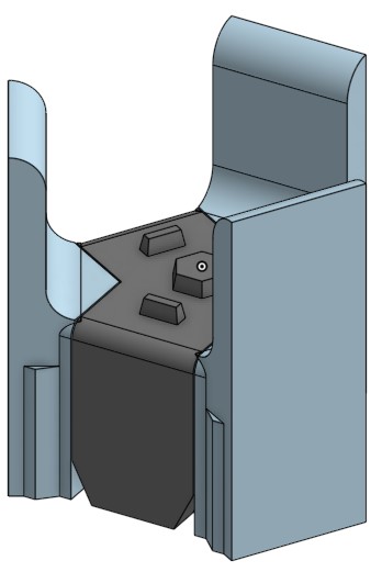
Base Plate
I designed a base plate for the parts to lock into. It was a bit tricky to create a repeating tiled pattern for the holes. I used OnShape's "assembly" environment to connect all the parts together using "fastened mates", to make sure that they all fit together properly. The image below shows the results (and gives you a good look at what I'm going for).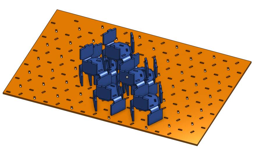
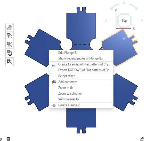
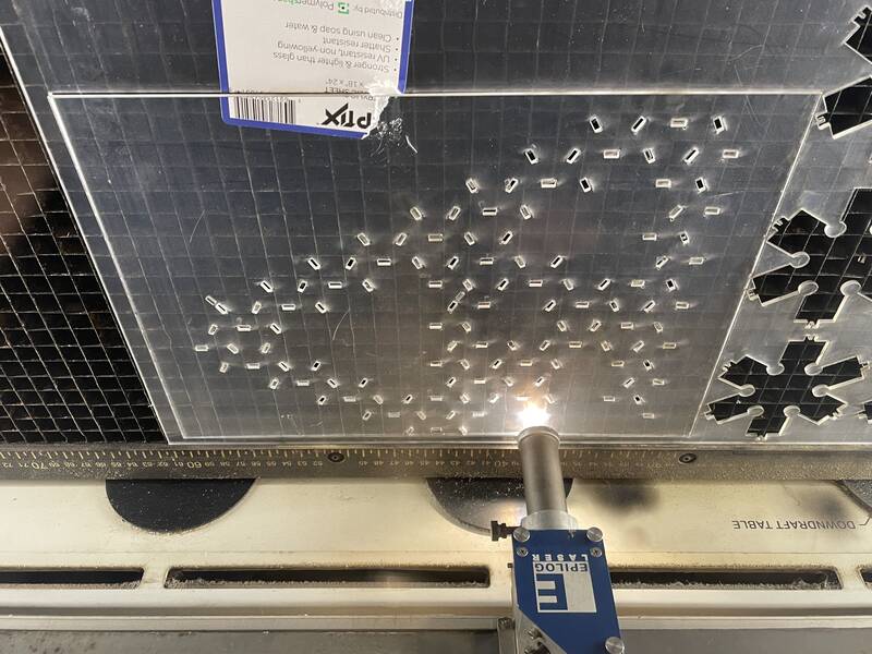
Laser Cutting
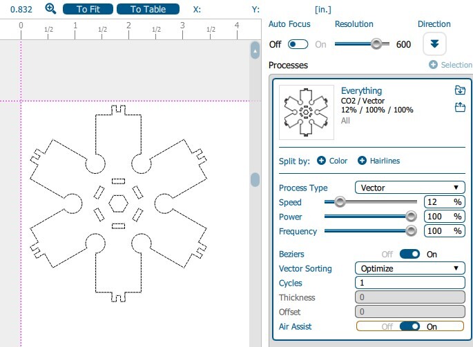
I exported the flat pattern of my crystal hex part as a DXF file, moved it to the computer controlling our laser cutter, opened it in Adobe Illustrator, and "printed" it. The speed may have been a little slow, but better safe than sorry.Material: .093" clear acrylic
Speed: 12
Power: 100%
Frequency: 100%
Manufacturing (First Revision)
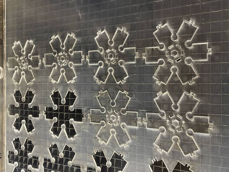
Here's the manufacturing process for the crystal hex pieces.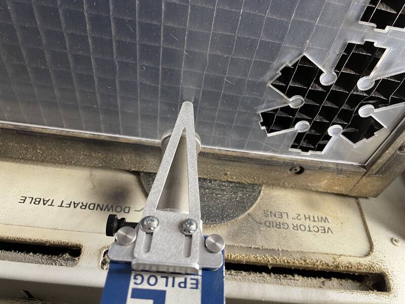
Problems and Revisions
I made three test pieces, and I was surprised at how well they fit together, but there were two serious problems. First, I designed the parts with just a friction fit between the tabs and slots, but that wasn't strong enough so the construction wasn't very strong. Second, it was extremely difficult to get the hot, floppy acrylic pieces exactly centered in the jig, so the pieces came out with different length legs, causing the whole sculpture to be crooked. A third minor problem was that the top and bottom uprights of the crystal hex weren't quite the same size.To fix this, I went back to the drawing board. I made the following changes:
- Make all bends "middle" rather than "inner" and "outer", so that the crystal hex is symmetrical from top to bottom.
- Modify the tabs so they make a "snap fit" into the slots.
- Add a center hexagonal cutout that will help to register the part in the jig.
- Add registration pegs to the lower bending jig that the cutouts in the part will fit into.
- Modify the lower bending jig to be in two parts, so I can align the part on the jig before starting to bend. This ended up being too complicated and not working well, so I didn't end up using this feature.
Manufacturing Version 2
Version 2 was a huge improvement: almost all the parts came out straight, and they make a very satisfying "click" when they snap together. I assembled them, and then set them up with a light box for some glamor shots
Hero Shots
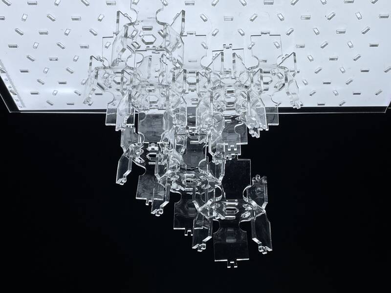
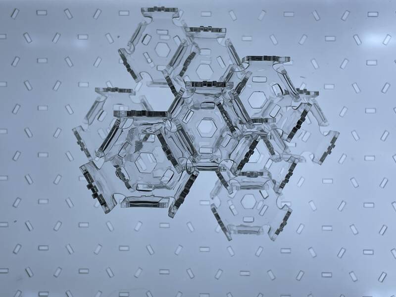
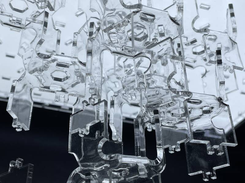
As for the look, it looks exactly how I imagined. Photos don't quite capture the way it catches the light. It's cool, but I dunno maybe not quite as cool as I'd hoped for. I decided early on to use only clear plastic because it's supposed to be like ice crystals, but a different version with pastel colors might be interesting.
Design Files
All of these are uploaded to my Fab repo.- week-03-crystal-hex-piece.step
- week-03-crystal-hex-base-plate.step
- week-03-crystal-hex-bending-jig.step
- week-03-crystal-hex-flat-pattern.dxf
- week-03-crystal-hex-base-plate.dxf
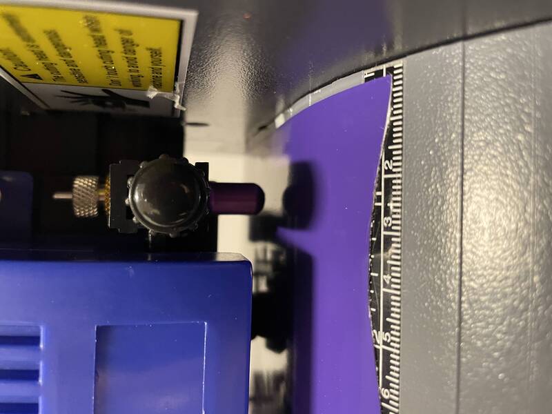
Vinyl Cutting
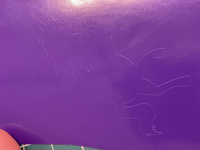
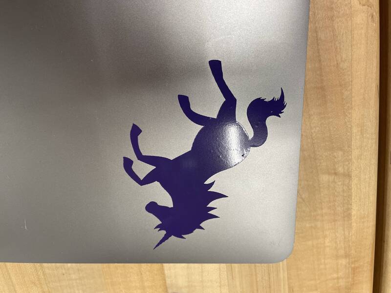
I spent enough time on the laser-cut construction kit that I could only do the bare minimum for the vinyl cutter. But since it's a new technology for me, I still learned a lot. (My original plan was to try to cut theater lighting gels and overlay them with backlit illumination to create a multicolored glowing image.) Instead, I just cut out a unicorn sticker, which was one of the files we had lying around on a lab computer. I hope to do more vinyl cutting soon!Vinyl Cutting Process
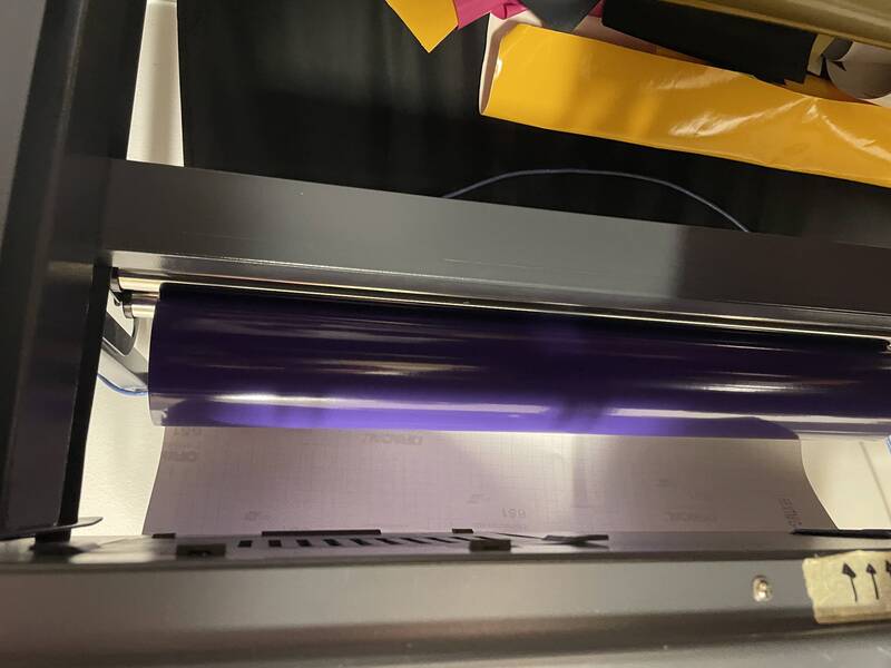
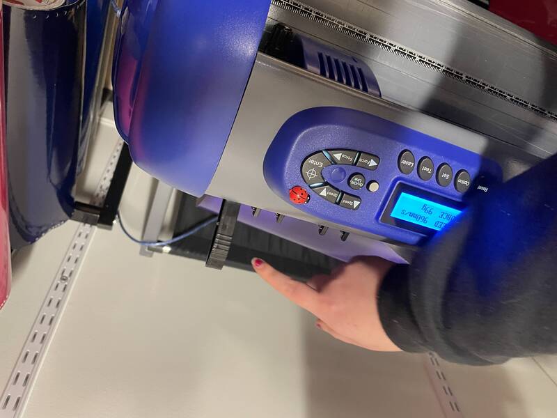
Our vinyl cutter is a USCutter TITAN 2 with a 53 inch bed. Steps for using it:- Start the control computer and launch "Sure Cuts A Lot Pro".
- Select a roll of vinyl to cut. Sticker vinyl has a paper backing; fabric heat transfer vinyl has a clear plastic backing.
- Release the clamping lever so vinyl can be loaded.
- Load the vinyl roll. Vinyl side should be face up, right edge should be close to the right side of the machine.
- Close the clamping lever to grab the vinyl.
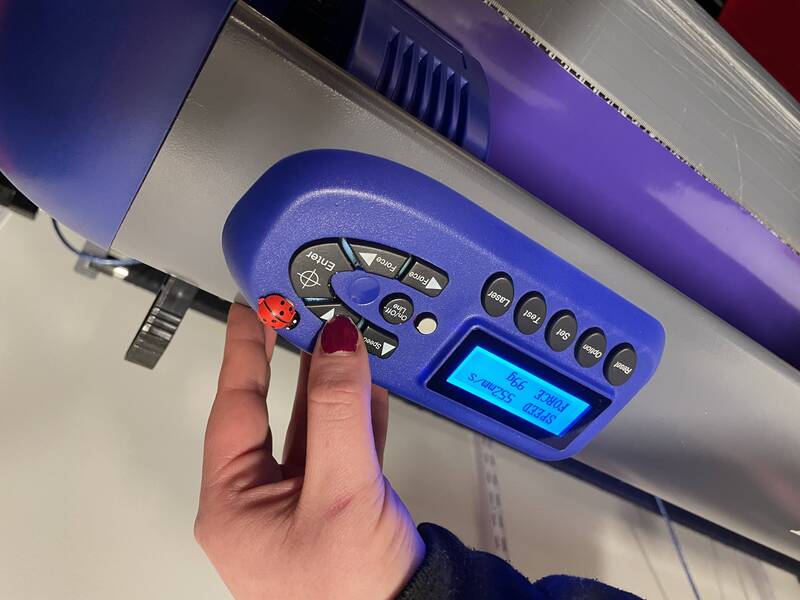
- Using the arrow keys on the control panel, set cutting speed and force. Ideal settings are listed on stickers on the machine. To experiment, I tried a fairly fast cut with higher-than-recommended force (960 mm/s, 99g force. Wait, now that I think of it it can't possibly move at 960 mm/s, I'll have to check that out later.)
- Press the "On/Off Line" button to activate zero-setting mode. Now use the arrow keys to move the cutter to the bottom right of the place you want to put your design. (This is different from a laser cutter or CNC, and is annoying.)
- Press the crosshair button to register this as the starting point, then press "On/Off Line" again.
- Load up a design in Sure-Cuts-A-Lot. You can draw in the program, but for serious work, import an SVG file.
- Choose "Cut with Cutter" to start the cut.
- Use a sharp knife to cut your design off the roll.
- Using an exacto blade or dental pick, "weed" your design by peeling off the negative space around the final sticker.
- Cover the sticker's face with transfer tape. Use a scraping tool to make sure it's firmly attached.
- Peel away the paper backing of the sticker.
- Stick the transfer tape and sticker to the object you want to stick to. Use a scraping tool again.
- Peel away the transfer tape, leaving the sticker behind.
- Clean up any bubbles. A trick I remember from my model airplane days is to poke a tiny hole in any bubbles with a pin or exacto blade, then squeeze the air out through the hole.
Group Lab Work
In our group assignment, we did the following tasks:- Learn about laser cutting technology and techniques, including kerf
- Learn to design and prepare a part for laser cutting
- Learn to operate the laser cutter
- Compare that part's size against the design file to estimate laser cutter kerf
As noted above, for my individual project I used a kerf value of 0.2 mm for 2.3 mm thick acrylic. This was a wild guess (I actually did this before lab so I had nothing to go on), and it turned out to be almost perfect.