Week 02: Computer-Controlled Cutting (Group work)
Group members:Zach Campbell
Dara Yanoff
Jason Goodman
Daniel Collins
Neil's assignment:
        group assignment:
            characterize your lasercutter's focus, power, speed, rate,
               kerf, joint clearance and types
Creating a Design File
To export the Fusion design into Adobe Illustrator, under the create tab, and selecting Project/Include,we chose to project the design. Using the default settings, we projected the front face of the design. Once that was finished, we right-clicked the sketch tab under the dashboard in order to export as a DXF file.
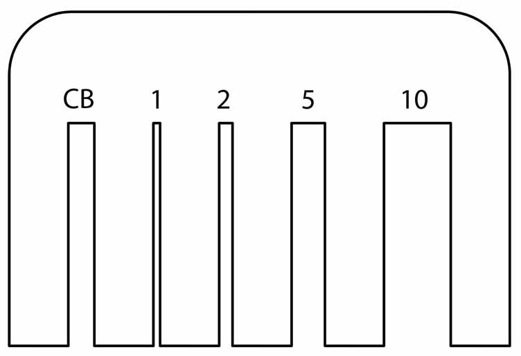
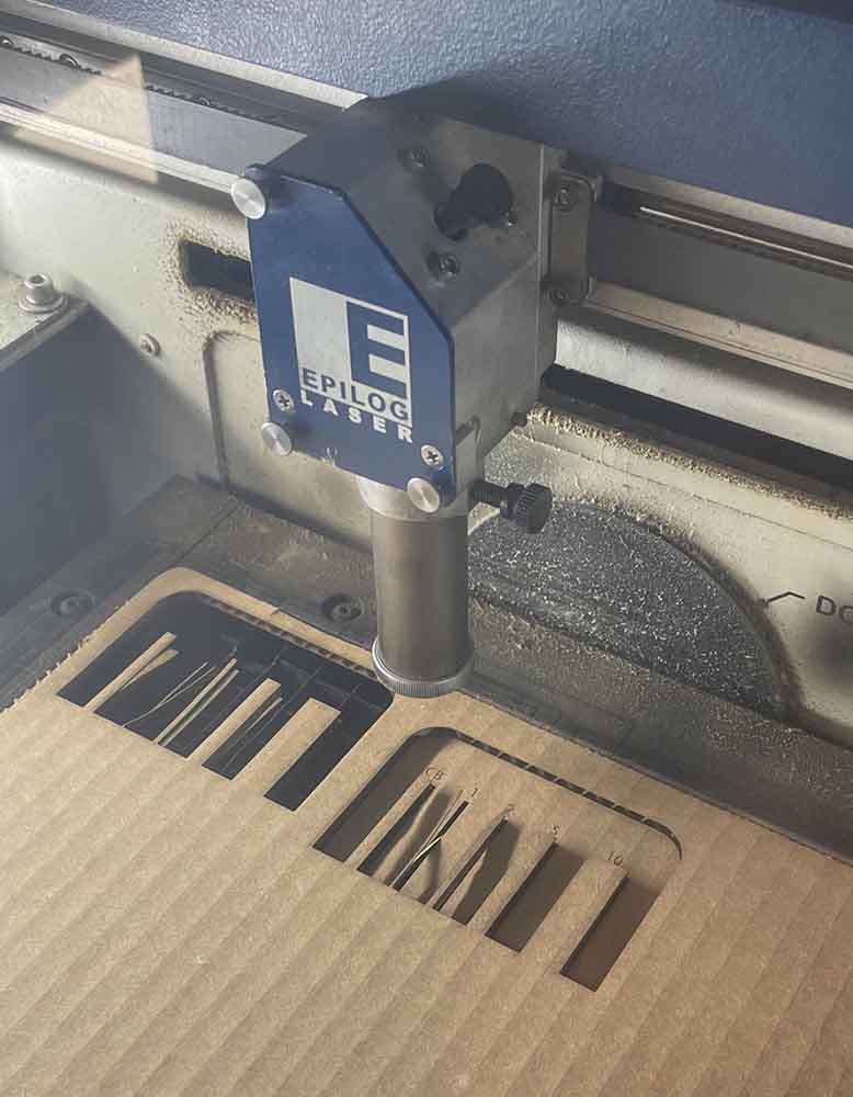
Then, using the text tool in Illustrator, we labeled the gaps with their corresponding measurements, CB (cardboard/ 3.9mm), 1 (mm), 2 (mm), 5 (mm), and 10 (mm). Now that the Illustrator design was finished, it was time to export the design into the Epilog Dashboard. From Illustrator, we prompt the software to print the file. By selecting the Epilog Laser Cutter and pressing print, it automatically opens Epilog Dashboard. Before doing this we make sure to select no auto-rotate and do not scale.
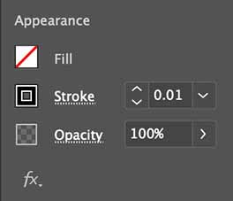
In Epilog Dashboard we are able to position the design on the layout grid, as well as set the engraving and vector properties such as frequency, speed, and power. For this specific cut of cardboard material, we set the engrave (raster) settings to have a speed of 75 and power of 20. With the cut (Vector) properties, we used a speed of 30, power of 40, and a frequency (rate) of 10. Also, within the Epilog Dashboard we were sure to turn on air assist.
Laser Cutting
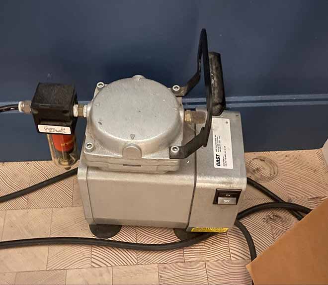
To start using the laser cutter, we turned on the machine itself, plus the building’s ventilation system to clear out harmful gasses. It’s also important to turn on the separate “air assist” air compressor, which helps the laser cutter blow away smoke and fumes from the beam path.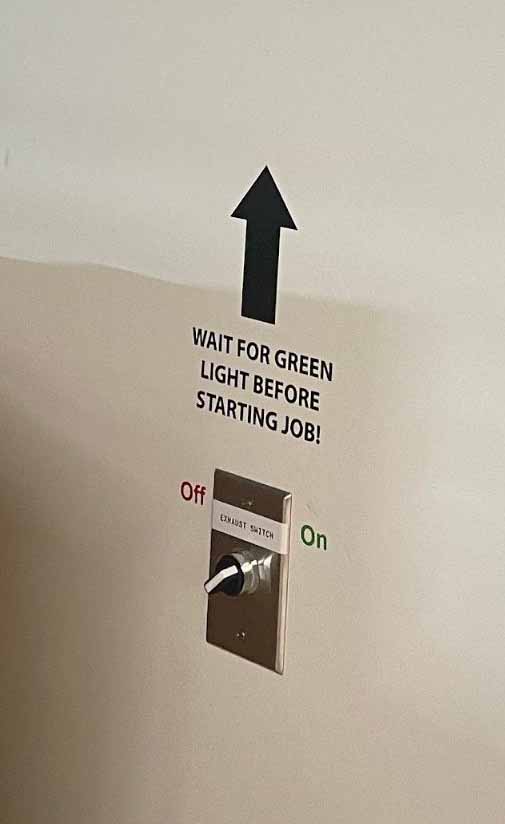
Now moving to the settings on Epilog itself, the first step of preparing the printer for cutting was to set the focus. The focus is the height of the bed. Using the focus tool, we are able to measure the exact height needed by slowly moving the joystick on the Epilog until it reaches the head of the focus tool. Pressing the joystick down ensures that the position of the bed is secured. The Epilog gives the user a red light beam to indicate where the laser will land with the first initial cut, so with this indicator we are able to set the jog, or the starting position of the laser. Using the joystick we set the laser to start in the top left corner of the material in order to reduce waste. Pressing the joystick inward secures the position of the laser head. Once this process is completed, we close the cover to the Epilog.
This sends the design to the Epilog for cutting. Using the joystick to navigate to the job settings, we chose our file for print. Once we are sure that everything is secure including the lid, ventilation, and positioning of the laser head we can press “go” to start the laser cut.
We are sure to keep an eye on the laser cutter, but like our instructor says “keep your eyes on it, not in it.” Which means to keep an eye on the printer during the process, however do not continuously look into the laser to avoid eye damage.
Measuring the Kerf
Once the part has been cut, we measured the kerf by comparing the actual size of the slots in our kerf comb to the size in the design file, using digital calipers. So for example one of the slots was 5 mm wide in the design, but we measured it to be 5.56 mm. This means the kerf is (5.56 - 5) = 0.56 mm. (Half the width of the laser beam is added to the cut on each side.)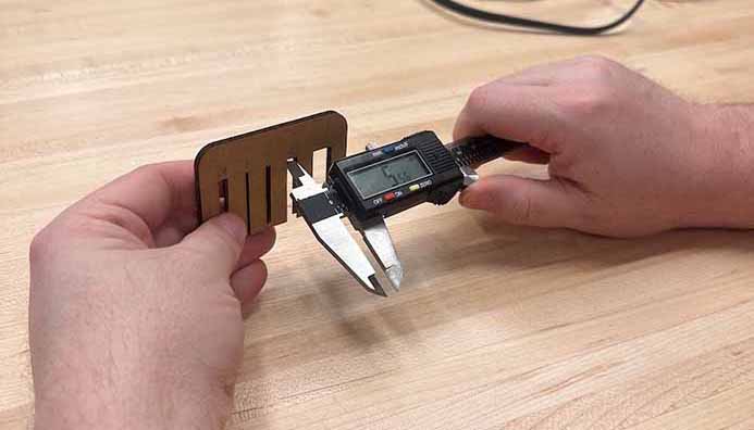
| Group 2 - Dan, Zach, Jason, Dara | Expected (mm) | Actual (mm) | Kerf (mm) |
|---|---|---|---|
| Cardboard (CB) | 3.9 | 4.25 | 0.35 |
| gapTwo | 1 | 1.36 | 0.36 |
| gapThree | 2 | 2.35 | 0.35 |
| gapFour | 5 | 5.56 | 0.56 |
| gapFive | 10 | 10.5 | 0.5 |