Hall Effect Magnetic Sensors
These small magnetic field sensors are the core of the project. They are able to measure magnetic fields in 3 axes to fairly high precision (some can easily sense the Earth's field, but I'm not sure I want that.) The device's resolution will be limited by the number of sensors I can fit into the grid.There are a wide range of these available as surface-mount componenents, for a price of $0.50 - $1.00 each in quantities of dozens, so I should be able to afford lots of them.
Key considerations for magnetic sensor selection:
- Manufacturability. The pin pitch must be greater than 1 mm to allow PCB fabrication with an 0.4 mm endmill.
- Solderability. Pins must be exposed, no ball-grid array components.
- Addressability. I need to be able to talk to dozens of these at once. Their I2C addresses should be changeable.
- Sensitivity. The sensors should be able to detect the Earth's magnetic field easily.
- Range. The sensors should not be overloaded by a small rare-earth magnet a few mm away.
- Library Support. Ideally, someone will have written a library to support the sensor so I don't have to.
Earth's magnetic field is about 30-50 microTesla (.03-.05 milliTesla). To have the resolution to sense it to within 10%, I need a sensor with a precision of 200-300 LSB/mT. I also want to sense ordinary ceramic magnets from a short distance away (about 5 mT total), and if possible not get overwhelmed by nearby rare earth magnets (hundreds of mT).
The MLX90393 looks great: 16-bit precision, 5-50 millitesla selectable range, 300-6000 LSB/mT precision. There's an Adafruit part based on this, so good Arduino library support (https://www.adafruit.com/product/4022). But milling and soldering is a problem: the chip pins are spaced 0.50 mm apart, and don't stick out.
Other options to look into:
These both come in easy to solder TSOP packages (1 mm pin spacing). TMAG5273 I think meets my sensitivity and range needs (820 LSB/mT, up to 266 mT range(!)), looks like TLE493 doesn't (resolution 65 microTesla)
The TMAG5273 also has a reprogrammable I2C address, and comes in four different models with different default I2C addresses. Someone has written I used a TMAG5273 Arduino library.
I selected the TMAG5273.
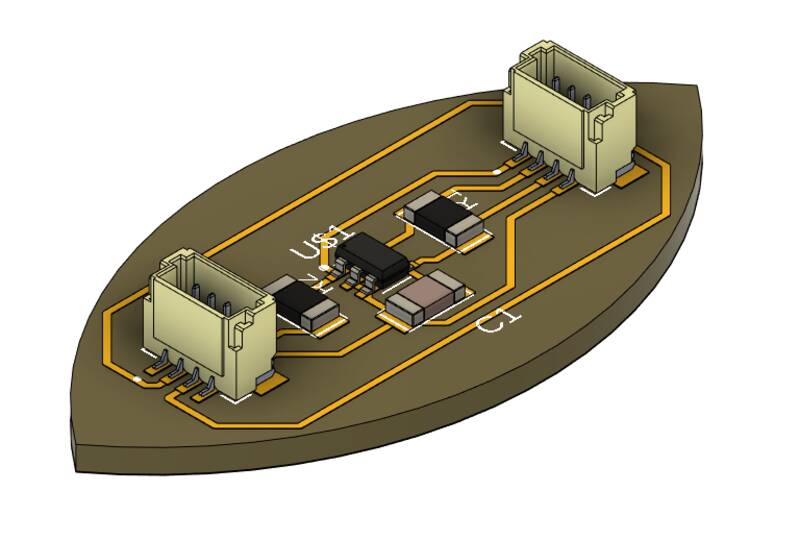
The final Beansprout TMAG5273 board from Input Devices week is shown as a 3-d model on the right. This board will not be part of the final design, but I was able to use it to test libraries and code for the magnetic sensors in Input Design week and Applications and Interfaces week.
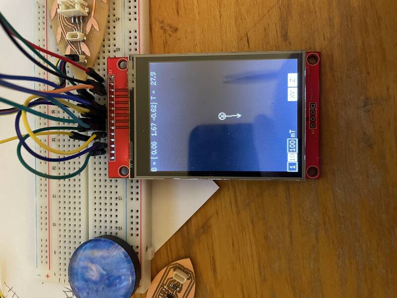
For Interface and Application Programing week, I used this sensor with an LCD screen to make a graphical user interface that shows the field arrow from one magnetic field sensor on the screen, with a touchscreen GUI to allow the user to change how it's displayed. During this week, I realized I needed to make some changes to part selection:
By experimenting with this setup, I found that the high-field-range TMAG5273A2 is probably not what I need. Even a 2 cm-wide neodymium supermagnet placed within 2 mm of the sensor isn't enough to exceed its maximum range of 266 mT. I should be able to get away with the TMAG5273A1 model, with a +/- 80 mT range and higher sensitivity.
I also found another problem: while the manfacturer offers both the TMAG5273x2 and TMAG5273x1 in four different versions (x=ABCD) that are identical but with different I2C addresses, the distributors (Mouser, Digikey, etc) don't have all those models available. It looks like at best I'll be able to get three different factory I2C addresses.
I also spent some time getting cuddly with the TMAG5273 datasheet, and learned a little about how to talk to lots of TMAGs at once. Each one either needs a unique I2C address, or needs to be on a separate I2C bus. The good news is the Xiao RP2040 has two easy-to-use I2C buses, and the TMAG5273 comes in four varieties (part numbers TMAG5273A2, TMAG5273B2, TMAG5273C2, and TMAG5273D2), which are identical except for the I2C address. But that only gets me a total of eight. But even better, the sensor allows you to reprogram its I2C address. The datasheet describes a way to do this with one extra wire per sensor, which is annoying. The TuYuXiao Arduino library describes a method for programming them using an R-C circuit and a MOSFET to make them turn on sequentially with a delay, so no extra control wires. My final addressing scheme is discussed in the Board Design page.
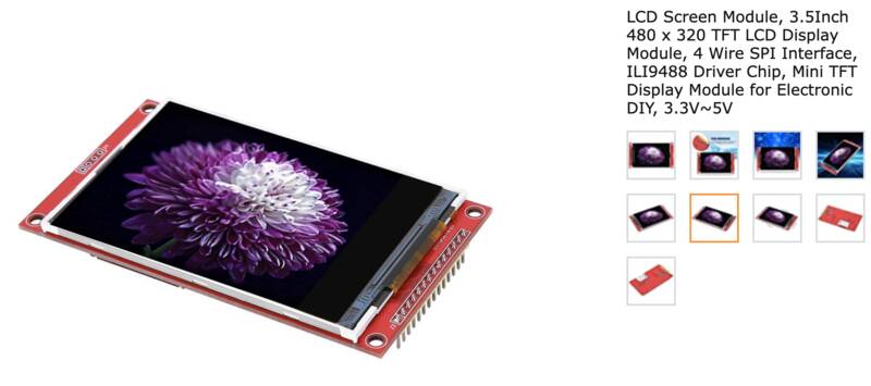
TFT Touchscreen Display
I want to use a touch screen display similar to a smartphone to display the magnetic field graphics, and to control the device.
Key considerations for magnetic sensor selection:
- SPI communications. Some of these displays use complicated parallel communications systems. To keep things simple, I will use 4-wire SPI.
- Color
- Large Dimensions. The sensors will be placed directly under the screen, so to show a large magnetic field structure, we need a big screen.
- High Pixel Resolution
- Touchscreen
- Library Support
- Low Cost. This works against most of the other criteria.
For Output Devices week I figured out how to use these displays. This turned out to be incredibly frustrating -- mostly because I made stupid mistakes -- so I'm glad I did it as a weekly assignment rather than waiting. My development process is discussed in Week 09: Output Devices.
For Interface and Application Programing week, I brought two previous assignments together to make a graphical user interface that shows the field arrow from one magnetic field sensor on the screen, with a touchscreen GUI to allow the user to change how it's displayed. This was a huge success, and for the first time let me see that my final project might work out well.
Microprocessor
Which processor should we use? Here are my selection criteria:- Manufacturability. The chip needs to work with Fab machining and soldering processes, as above.
- USB programmable. From previous experience, I am done with chips that don't provide native USB support. No more FTDI cables, thank you.
- FAB Academy compliant. Fab Academy allows "bare chips" or solderable processor modules, but not separate commercial dev boards.
- Enough pins. See "pin counting" below.
- Speed. If I end up doing the "3-d remote field camera" concept, this chip is gonna have to do a lot of math.
- Arduino Compatible. My primary dev platform will be Arduino.
- CircuitPython Compatible. The "3-d remote field camera" concept may require me to use CircuitPython to take advantage of Numpy and other packages.
- Multiple I2C interfaces. This will make talking to lots of sensors easier.
Pin counting
Let's figure out how many total microcontroller pins we'll need to make this work. These numbers are for three possible methods of programming the magnetometers' I2C addresses:- "Control Lines": Each bank of magnetometers is powered from a GPIO pin on the microcontroller. At startup, the banks are turned on one at a time, their I2C addresses are reprogrammed, and then the next bank is powered up. Benefits: simple.
- "Shift Register": Same as above, but the banks are powered by the output pins of a shift register. Requires 3 wires to control the shift register. Benefits: 3 pins can control up to 8 banks of magnetometers.
- "RC Timing": There's only one power control line. When activated, it turns on the first bank of magnetometers, and starts charging an RC circuit. Once that has charged, it activates a MOSFET to turn on the second bank, and so on. The microcontroller programs the I2C addresses of each bank as it activates. Benefits: only one control pin. Drawbacks: requires precise timing and lots of components.
In addition, more pins will be needed to control the TFT display, the touchscreen, and to power everything. I made a table of the resulting pin counts for each option.
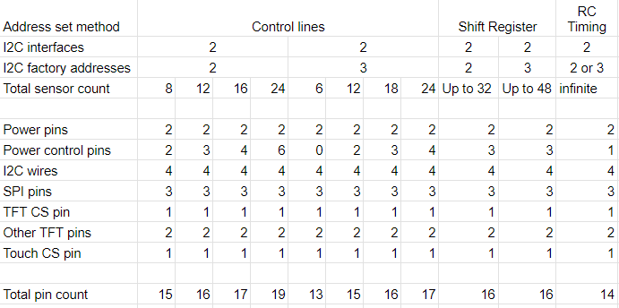
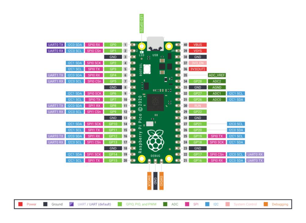
The Seeed Xiao RP2040 has a total of 14 pins. Looks like the only way to make this work with a Xiao is to either have 6 or fewer sensors, use the "RC Timing" method. I am really reluctant to use that method, it'll be super tricky to get working and will involve lots of analog electronics. Instead, I think I'm going to switch to a Raspberry Pi Pico, which uses the same processor as the Xiao but has 40 pins. This will give me plenty of pins to use the simple Control Line method. The Pico is about twice the physical size of the Xiao, but it's still small enough to fit into the case.