   individual assignment:
      write an application that interfaces a user with an
         input &/or output device that you made
   group assignment:
      compare as many tool options as possible
Group Work
For our group work this week, we did some background research on various programming languages and interfaces that can be used to create applications. My group's findings are documented in this Google Docs spreadsheet; the other Wheaton group's work is documented here. We were asked to learn more about Julia (a general-purpose programming language similar to Python), PyClutter (which is apparently obsolete), Scratch (a visual block-based language intended for kids), Arduino (which we all know and love), and OpenGL (a core-level 3-d graphics API). I spent a bunch of extra time looking at Julia after this: it seems really powerful, with an easy-to-use command line REPL similar to Python but supporting fully-compiled output. The one thing I didn't like was that I didn't see any way to draw application windows directly onscreen the way you can with Python/Tk. Maybe I just haven't found that yet.
Our groups also worked through the steps of setting up and running an example code that interfaces an Arduino to a Python/Tk window using serial data communications. The source code we used, and the steps for installing libraries etc, were provided by our instructor here. We found that installing Python and Python libraries was pretty easy on a Mac, but we had a hell of a time with path environment variables on Windows.
In the end, though, we created a set of buttons onscreen that, when pressed, send a character "1" through "5" to the Arduino over a serial connection. The Arduino then blinks its built-in LED that many times.
Concept
My plan for this week is to push forward with my final project, figuring out the core user-interface technologies to work with the touchscreen interface I plan to use. I have already figured out the TFT screen in Output Devices week, and the TMAG5273 magnetometer in Input Devices week, now I have to put them together with a touchscreen. My steps will be:- Write code to draw arrows of different shapes and sizes on screen.
- Write code to read a single magnetometer and plot the field as an animated arrow onscreen.
- Figure out how to use the TFT's touchscreen.
- Add touchable buttons to the TFT display, so you can change how the field arrow is presented.
Drawing Arrows
First step: I need to be able to draw arrows on screen of various shapes and sizes. My tft_arrow.ino code does that.
My code uses stealth linear algebra to do its job. First, I define the X,Y coordinates of the start and endpoints of three lines that draw a "standard arrow", pointing in the +X direction with length 100 pixels:
  int unit_startx[] = {0,100,100};
  int unit_starty[] = {0,0,0};
  int unit_endx[] =   {100,85,85};
  int unit_endy[] =   {0,10,-10};
Then I do a coordinate rotation and scaling to transform these points so they're aligned with the (dx, dy) coordinates:
  startx[i] = x+(unit_startx[i]*dx - unit_starty[i]*dy)/100;
  endx[i] =   x+(unit_endx[i]*dx   - unit_endy[i]*dy  )/100;
  starty[i] = y+(unit_startx[i]*dy + unit_starty[i]*dx)/100;
  endy[i] =   y+(unit_endx[i]*dy   + unit_endy[i]*dx  )/100;
This is all done with integer math and no trigonometric functions, for speed. This routine will work on any shape no matter how complicated, so I can get fancy with my arrows if I want. Here's a video of the result:
Drawing Fields

Next, I merged the tft_arrow.ino code with my TMAG5273_basic_rp2040_twoi2c.ino code from Week 11 to create code with an animated field line arrow.
But one more thing is needed: I want to show all three dimensions of the magnetic field arrow. A standard notation used in physics to draw vectors pointing into or out of the page is the dot/cross notation: a cross represents the tail feathers of an arrow as it points away from you; a circled dot represents the tip of the arrow pointing toward you. I wrote additional code to draw these symbols for the Z-component of the magnetic field, and to make them get bigger and smaller as the field gets stronger or weaker.
Here's a video of my result!
In real life it's not quite as flickery-looking as it appears in this video, there's some sort of interaction between the camera frame rate and the screen.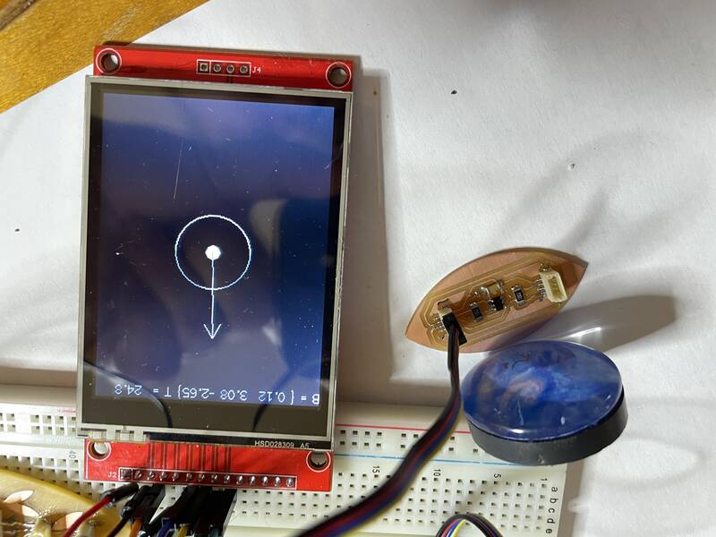
tft_magnet.ino in action. The screen indicates that the magnetic field is poking out of the table and toward the magnet.Sensitivity, scaling, and filtering
One thing I noticed is that I'm not coming anywhere close to the magnetic field limit of the TMAG5273A2 sensor (266 milliTesla). Even the lower-sensitivity range (+/- 133 mT) is much higher than I need. I haven't tried really strong supermagnets with this, but I think it should be safe to use the more sensitive TMAG5273A1 sensor, which can select between +/- 80 mT and +/- 40 mT range.
Also, the Arduino driver I'm using assumes I'm using the A1 version, so the field values reported in the screenshot are off by a factor of 133/40. I could fix this in code, but why not get the most appropriate chip anyway?
Ideally, I want to use this thing to detect the Earth's magnetic field. I had two challenges in doing this. First, the sensor needs to be calibrated: it reports a persistent field that doesn't change as the sensor board is rotated. I dealt with this by having the code subtract off a "zero field" calibration value. Second, individual field measurements at this scale are very noisy, the arrow twitches and jiggles. It's not clear if this is a limitation of the sensor, or if it's picking up real variations in magnetic field caused by nearby electrical wiring. The sensor is already set to collect and average individual magnetic field measurements (TMAG5273_CONV_AVG_32X) which is the maximum. I reduced the noise further by creating an autoregressive filter, that continually averages combines the new measurement with old measurements:
Bx_smooth = smoothness*Bx_smooth + (1-smoothness)*Bx;where
Bx is the latest measurement, Bx_smooth is the smoothed value, and I used a smoothness value of 0.9. Later on, I may implement a true moving average filter, but this is simplest.
With this addition, the arrow responds to changes a little more slowly, but is much less jiggly. I was able to use this to measure the direction of the Earth's magnetic field, correctly toward the north and into the ground (I'm in North America).
Using the Touchscreen
The touchscreen uses the same SPI connection as the display, but it has separate pins. I wired them up as follows:- T_CLK --> SCK
- T_CS --> Xiao pin D6
- T_DIN --> SDI (MOSI)
- T_DO --> SDO (MISO)
- T_IRQ --> not connected
T_CS to the TFT_eSPI config file, which should activate the touchscreen feature of the library, and ran the Touch_calibrate.ino example.
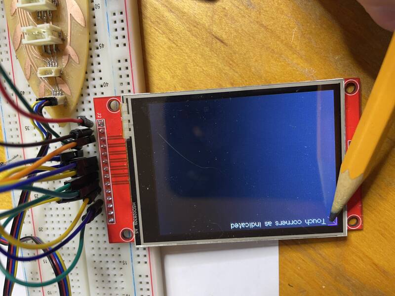
This example provides calibration data so the TFT library knows what spot you're touching. My calibration results for the 2.8" ILI9341-based screen were:
// Use this calibration code in setup():
  uint16_t calData[5] = { 306, 3386, 449, 3398, 2 };
  tft.setTouch(calData);
I then adapted the On_Off_Button.ino sketch to try a simple user interface example. I removed the parts that store calibration data in an ESP32's onboard memory.
A Simple Touch GUI
I had no trouble using the touchscreen demos, so I added the following to my magnetic-field-display code:- Code to see if the touchscreen has been touched
- A
Buttonclass that can draw a button on the screen, and test whether a touch is inside that button - Three buttons to change the scale of the vector arrows from 1, 10, or 100 mT for an arrow as wide as the screen
- Two buttons to turn on and off drawing either the XY component of the field, or the Z-component
Next Steps
The next steps in my final project are to get this working with lots of field sensors. The pin count on the Xiao module is a bit of a problem: I have two pins left over. That will be enough to give me an additional I2C bus: since the sensors come with 4 different default I2C addresses that gives me a total of 8 sensors. To get more, I'll need to reprogram their addresses, which will require additional GPIO pins to switch them on and off. It might be possible to reduce the pin count for the TFT module somehow; if not, I may have to use the Raspberry Pi Pico, which is larger than the Xiao but gives me all the GPIO pins I could ever want. I bought some of these just in case.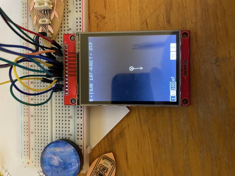
Design Files
- tft_arrow.ino -- draw an animated arrow on the TFT screen
- tft_magnet.ino -- Interface with a magnetometer to draw a magnetic field arrow on the TFT screen
- tft_magnet_touch.ino -- Touch-screen application to use a magnetometer to draw a magnetic field arrow on the TFT screen. Buttons let you adjust field arrow scale and visibility.
- JCG_ILI9341_XiaoRP2040.h -- User Setup file for the Bodmer TFT_eSPI library, configured for my 320x240 ILI9341-based touchscreen TFT module.