   individual assignment:
      add an output device to a microcontroller board you've designed,
         and program it to do something
   group assignment:
      measure the power consumption of an output device
Group work
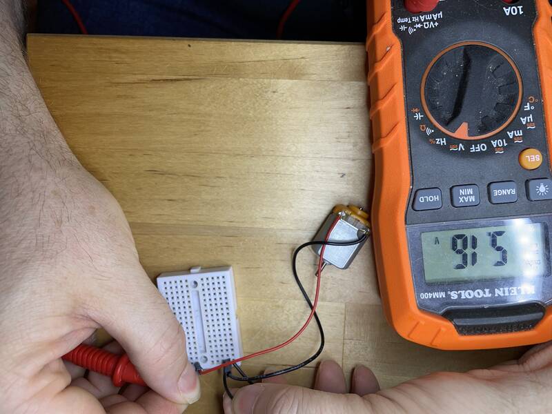
I was unable to complete this week's group assignment with my group, so I did it on my own and am writing up my results here.The group assignment was to measure the power consumption of an output device. Power is calculated by multiplying the voltage across a component times the current through the component:
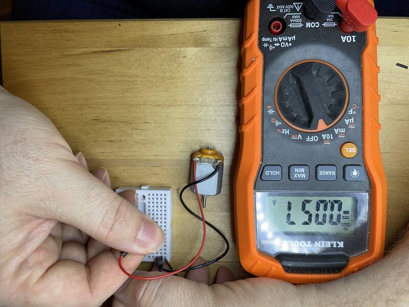
P = I VI calculated the power flow through a small DC electric motor. I connected it to a 5V, 2A DC power supply. I connected my multimeter across the motor's terminals, and measured V = 5.16 volts while it was running. Then, I switched the meter into 10A current mode, and measured the current flowing through the circuit. (It's important to put the meter "in the loop" while doing this, if you connect it across the motor you'll create a short circuit through the meter!) I measured I = 0.057 A when the motor was free-wheeling, and I = 0.531 A when the motor's axle was held in place and unable to turn.
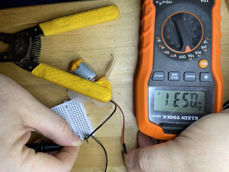
Thus, we can calculate that the motor consumes 5.16 x .057 = 0.29 watts when freewheeling, and 2.74 watts when stalled. It may seem surprising that the motor consumes less electrical power when stalled, given that when it's not moving it cannot produce any mechanical power. The explanation is that in this case, the electrical power is being turned into heat rather than motion.
About this documentation
This week's documentation is going to be a lot less formal than previous weeks. Instead of explaining step by step what I did and how I did it, it's going to focus on my screwups, my problem-solving process, and how I tried and failed and eventually succeeded. The heroes' journey, I suppose, with a really dumb hero. One thing's for sure, if you're new to Arduino it's worth reading, just to see that you're not alone in struggling, and maybe you'll learn from my mistakes.I did keep running notes of my step-by-step process, but they're not very readable. It's all documented in my week09-notes.txt file, swear words and all. On this page, I give a summary of what I tried, what I learned, and include little pull quotes from the running notes as comic relief.
Individual Assignment: TFT Displays
My final project will be a magnetic field mapping device. If possible, I want to integrate the display and sensors into a handheld package, so you can see the fields on the device. That means I really want a cool sexy color display. (If I can't get this to work, I'll do the visualization on a desktop computer, but that's less cool.)TFT LED displays are the best option for high-resolution color displays compatible with Arduino and other microcontrollers. They have screens about the size of a cell phone, display thousands or millions of colors, and can use the SPI interface supported by many microcontrollers. Many of these boards also include resistive touch-screens, but that's a topic for Input Devices week. They are generally powered by a driver chip mounted in the edge of the display.
One of the most common driver chip families is the ILITek series. Here are the specs for a few ILI driver chip models:
| Chip (link to datasheet) | Pixels | Colors |
|---|---|---|
| ILI9341 | 240x320 | 18-bit |
| ILI9481 | 320x480 | 18-bit |
| ILI9486 (no idea how this is different than ILI9481) | 320x480 | 18-bit |
| ILI9488 | 320x480 | 24-bit |
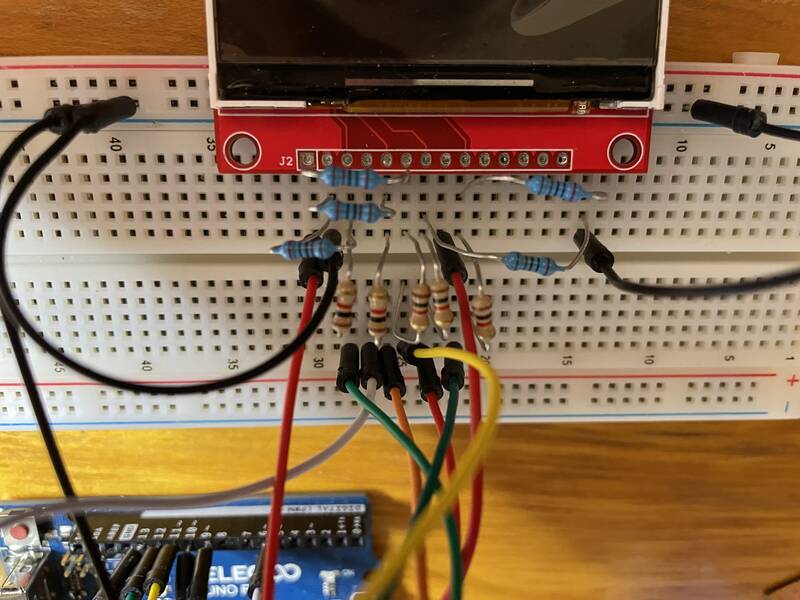
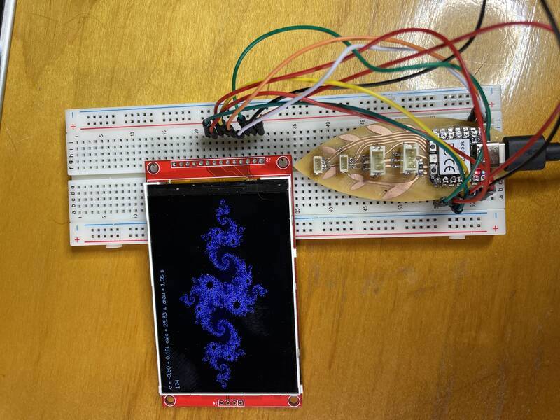
My "Beansprout" dev board has multiple I2C ports, but no SPI port. It does, however, provide optional pins to plug it into a breadboard, so I used that to wire up the TFT displays. I don't know whether "crappy rat's-nest of wires" is allowed this week, but I had enough trouble getting this to work that I don't have time to mill a new board.
The biggest problem with these TFT displays -- and it's a huge problem -- is that you can buy them for super-cheap on Amazon for like $16-$20, and you get what you pay for. They may include no information about what driver chip is included, no libraries or how-to documentation, and are unlabeled, so you have no idea whether the board you found in the lab is the same as the similar-looking thing you found on the Internet.
In the end, I tried to work with all of the following:
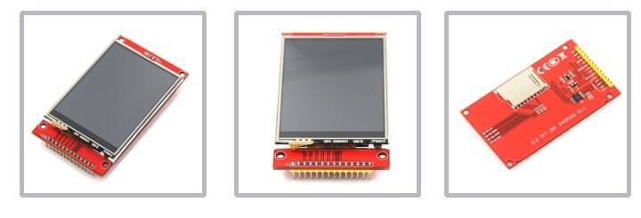
- HiLetgo ILI9341 2.8" SPI TFT LCD Display Touch Panel 240X320 with PCB 5V/3.3V STM32
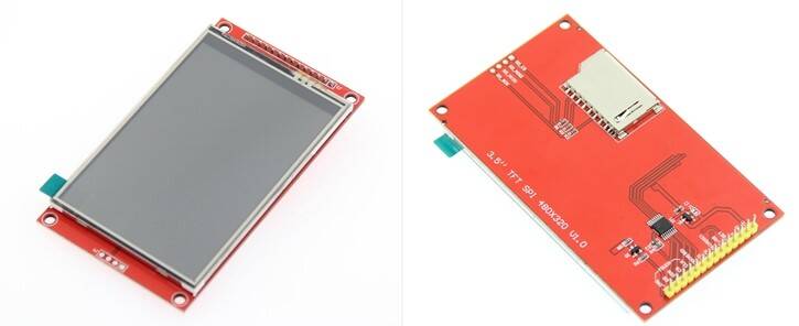
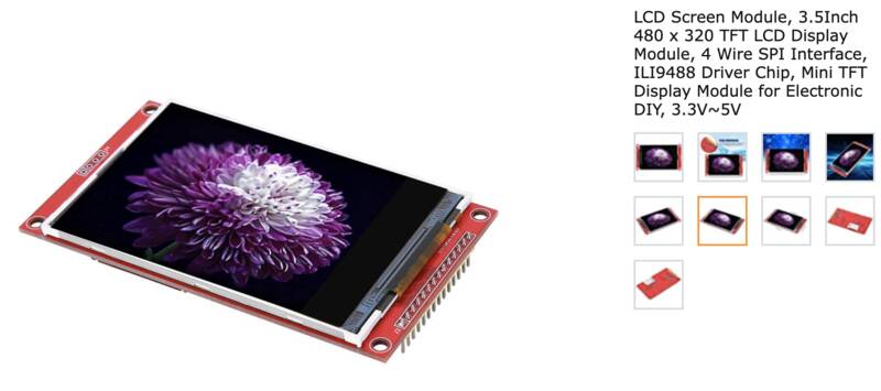
- LCD Screen Module, 3.5Inch 480 x 320 TFT LCD Display Module, 4 Wire SPI Interface, ILI9488 Driver Chip, Mini TFT Display Module for Electronic DIY, 3.3V~5V
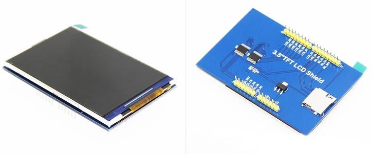
- 3.5 inch TFT LCD Shield This is a plug-in Uno shield that does 8-bit parallel ONLY.
These things don't have documentation. They don't have part numbers printed on them. They don't have support websites. The manufacturer doesn't have a web presence except for an Amazon store page, and bunch of yahoos on discussion forums and wikis trying to get them to work.
Now, there are companies that provide good support for these. Adafruit, in particular, has a set of lovely libraries for TFT displays they sell, full tutorials and documentation. What I should have bought is a Adafruit 3.5" TFT 320x480 + Touchscreen Breakout Board w/MicroSD Socket - HXD8357D. In addition to great support, it has a two-sided header so you can use it in either 4-wire SPI mode or 8-wire parallel mode. It also has a touchscreen. But it was out of stock when I went to order stuff. Instead I planned to try to use Adafruit's lovely libraries with these no-name Amazon boards.
Setup Hell
Getting these to work was pure hell. I spent at least 12 hours going around in circles, trying various combinations of display, microcontroller, driver libraries, and example codes. Is the display broken? Did I miswire them? Is the library not compatible with this board? Is my dev board not soldered right? Did I not configure the example code correctly? In the end, it was just me, making a stupid stupid rookie mistake.
I tried to get simple example scripts provided by various library developers running on the following boards:
- An Arduino Uno (more on that later)
- My Beansprout dev board (Seed Xiao RP2040)
- A fresh Seeed Xiao RP2040, just in case my Beansprout got mis-soldered.
Here's a list of the libraries and tools I tried out:
- Adafruit Graphics. This is a common core of graphics routines that many people write drivers to be compatible with.
- Jaret Burkett's ILI9488 library. This tries to be compatible with the excellent Adafruit GFX library, but it's slow.
- Bodmer's TFT_eSPI library. This one's really well developed with advanced features like sprites and anti-aliasing, and support for advanced processors like the ESP32 and RP2040. In the end I went with this, but I had a hell of a time getting it to work at first.
- moononournation 's Arduino_GFX library. Didn't work, may not be compatible with Uno.
- ZinggJM's ILI9486 library. At this point I was starting to wonder if they'd sold me a 9486 and said it was a 9488 on the Amazon page.
- The stuff linked to from the Uno TFT shield's documentation. This doesn't provide any graphics library support, it just shows you how to shove raw hexadecimal at the display.
- The 2.8", 240X320 touchscreen display just displayed a pure white screen, whether I used the Bodmer library or the Adafruit library.
- The 3.5" 320x480 non-touchscreen display gave a ghostly white screen that faintly showed the demo graphics, plus a bunch of dark horizontal lines. It did this consistently on the Uno with the Jaret Burkett, Bodmer, and ZinggJM libraries. Intriguingly, if you jiggled the wires a bit, or for a moment when you turned it off, it briefly looked better. (In hindsight, this was a clue.) On the Xiao RP2040, I just got a pure white screen, except for some garbage pixels in the top left corner, which ... well, read the pull quote.
- The 3.5" TFT LCD Shield worked fine when plugged into an Uno and running their example software. But that's useless for me, because my final project can't use an Uno, this display does 8-wire parallel ONLY, and the Seeed Xiao boards don't have enough pins to do that. Also I need a good graphics library to draw magnetic field lines. I couldn't get the Bodmer library to work with it.
Breakthrough
In the end, what saved me was Neil's notes. Or not the notes specifically, but a statement buried two links deep into the Wiki for the UCGLib graphics library he used:"The red breakout board from the following picture is a 3.3V board. It can be connected to the Arduino Due, but requires level shifters for the Uno and Mega boards."3.3V? Level shifting? What? Most of my efforts were focused on getting these displays working on the Arduino Uno. I got a blank display with the Xiao, at least the Uno showed something crappy. But the Uno uses 5-volt logic. And it turns out that the 240x320 display and the 320x480 one are both 3.3V only.
olikraus, "How to Connect a ILI9341 Display"
How could I screw this up? Didn't I check for voltage compatibility? I sure did! The Amazon pages for both displays describe the as "5V/3.3V". The 240x320 one says in the description "5V compatible, use with 3.3V or 5V logic." This is a lie. Adafruit -- God I love Adafruit -- goes into detail about how their boards use level shifters to be 3.3V or 5V compatible, so I didn't think twice about whether the Amazon ones did too.
Farther down on the page, in fine print, they both say something about "Logic I/O Voltage: 3.3V (TTL). Apparently the LED backlight takes 5 volts but the driver chip doesn't. Arrrrgh.
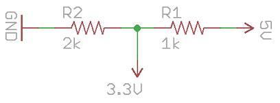
Of course this doesn't explain why the Xiao didn't work, that's a 3.3V chip. But since the Uno was almost working, I decided to stick with that. But I don't have any level shifting chips on hand. Is it possible to convert from 5V to 3.3V with just parts on hand? Yes, by adding a voltage divider to each digital output. Is it pretty? No. Did it work? Also no.
The Uno was a bust, so I went back to the Xiao RP2040 and tried again, wiring it up exactly the same as before, using the same Bodmer TFT_eSPI library as before. And this time it worked! I must have miswired it the first time, and then got so focused on the Uno I never tried the Xiao again.
A Working Setup
Here's my configuration and setup to get the 320x480 display working.- Driver library: Bodmer's TFT_eSPI
- Test script: TFT_eSPI/examples/480 x 320/TFT_graphicstest_one_lib/
- Wiring hookup:
  Xiao pin --> Display pin
  3V3 --> VCC
  GND --> GND
  D7 --> CS (Chip select)
  D0 --> Reset (TFT reset)
  D1 --> DC/RS (Data vs command selector)
  D10 --> SDI (MOSI)
  D8 --> SCK
  D3 --> LED (PWM LED brightness)
  D9 --> SDO (MISO)
- The Bodmer library wants you to create a User_Setup.h file in the library directory itself to configure your particular board and screen. Here's the important parts of mine:
  #define USER_SETUP_INFO "JCG_ILI9488_XiaoRP2040"
  #define ILI9488_DRIVER
  #define TFT_BL   D3            // LED back-light control pin
  #define TFT_BACKLIGHT_ON HIGH  // Level to turn ON back-light (HIGH or LOW)
  #define TFT_CS   D7  // Chip select control pin D8
  #define TFT_DC   D1  // Data Command control pin
  #define TFT_RST  D0  // Reset pin (could connect to NodeMCU RST, see next line)
  #define TFT_MISO D9
  #define TFT_MOSI D10
  #define TFT_SCLK D8
  #define LOAD_GLCD   // Font 1. Original Adafruit 8 pixel font needs ~1820 bytes in FLASH
  #define LOAD_FONT2  // Font 2. Small 16 pixel high font, needs ~3534 bytes in FLASH, 96 characters
  #define LOAD_FONT4  // Font 4. Medium 26 pixel high font, needs ~5848 bytes in FLASH, 96 characters
  #define LOAD_GFXFF  // FreeFonts. Include access to the 48 Adafruit_GFX free fonts FF1 to FF48 and custom fonts
  #define SMOOTH_FONT
  #define SPI_FREQUENCY   80000000
  #define SPI_READ_FREQUENCY  80000000
And oh man is it fast. The Uno was able to get through the standard "TFT_graphicstest_one_lib.ino" graphics test script in about 10 seconds, compared to several minutes on the Uno. Yes the RP2040 can do SPI at almost 80 Mhz, and the display can keep up, and it goes through Dupont wires and a breadboard just fine.
My Own Code
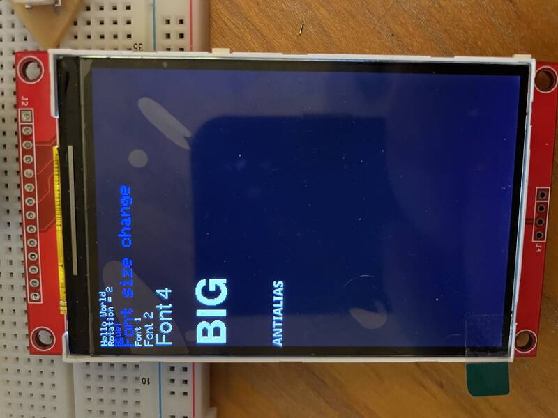
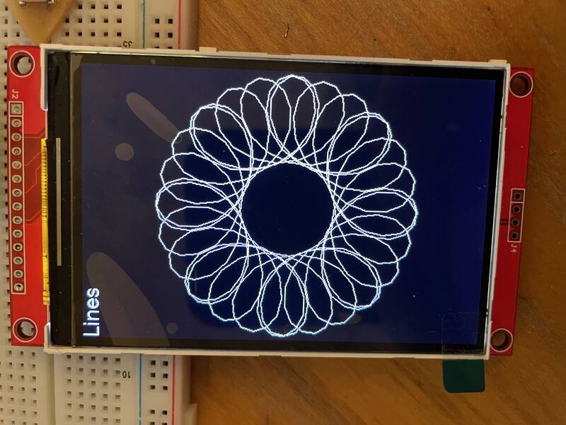
With a working display, I set out to learn more about the TFT_eSPI library's capabilities. As advertised, it can draw anti-aliased lines, moving sprites, and transparency. It can do "direct memory access", sending data directly from the microcontroller's memory to the display. I didn't mess with any of that. But I did learn how to print to the screen, use different fonts, and draw lines on the screen. Mytft_testing.ino sketch was my attempt to play around and learn these features. It displays text in a variety of fonts, then clears the screen and draws a "spirograph" pattern.
It's a great library but man, I could not find any well-written documentation! Just a bunch of patch notes that say "it can now do XYZ" and you're expected to dig through the code to figure out how.
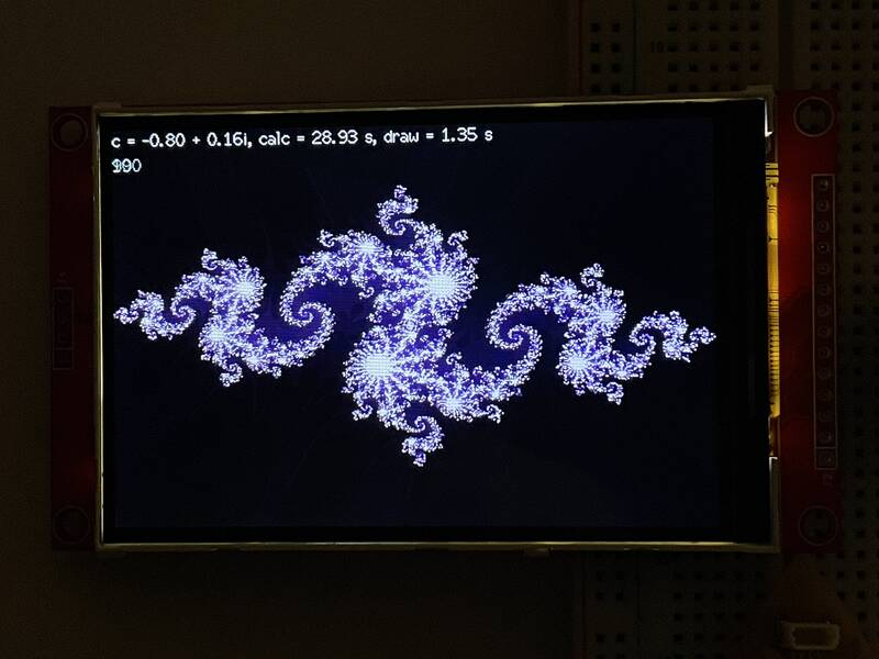
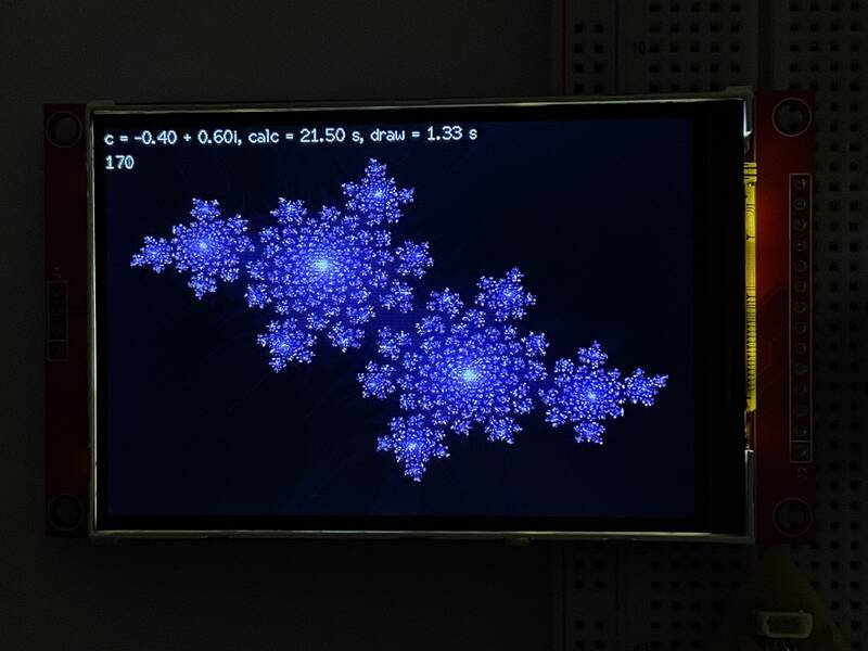
Back to Julia
I wanted to wrap up with something cool, so I modified my Julia set code from Week 4 to display a Julia set on the TFT screen. The main change was to change the "colors" from different sizes of O's output to the serial port, to an actual color map output to the TFT. I'm drawing pixels onedrawPixel() at a time, if there's a faster way to do it I haven't figured it out yet.
I also learned that the RP2040 doesn't have a hardware floating point processor. That might be an issue for my final project.
Lessons Learned
- When you've got one solution that almost works (the Uno), and one that totally doesn't (the Xiao), it's easy to focus on the one that almost works. But sometimes the total failure has a simple fix, and the near-success is actually a non-starter.
- Getting the logic voltage level wrong is a really easy mistake to make, and it can be costly. I'm lucky this didn't fry the whole display.
- Does your Fab Academy devboard need an SPI port? Yes.
- Never trust the specs on an Amazon page. If the manufacturer doesn't give you detailed specifications, you're wasting your time.
- Adafruit is the best. Always buy Adafruit.
- Read Neil's notes. They're impenetrable but there's gold in that vault.
Design Files
JCG_ILI9488_XiaoRP2040-- Setup file for TFT_eSPI librarytft_testing/-- Arduino sketch to try out fonts and line drawing.tft_julia.ino-- Arduino sketch to draw Julia sets on a TFT display.week09-notes.txt-- Running notes for this week's work. I stopped taking notes once things started working.