individual assignment:
    browse through the data sheet for your microcontroller
    program a microcontroller development board
      to interact (with local input &/or output) and communicate (remotely)
    extra credit: use different languages &/or development environments
group assignment:
  compare the performance and development workflows for other architectures
Group Work
Group work for the week is documented here. Probably the biggest thing I got out of the group work personally was a chance to look at the Seeed Xiao modules, which I hadn't used before. Impressive specs, and the ability to solder them directly onto a PCB really opens up some possibilities!Introduction
I have quite a bit of experience with embedded system programming on the Arduino platform, so I'm going to challenge myself to try some new methods and techniques. I also know that my final project might involve some fairly intensive floating-point computation, so I need to learn to use a modern high-end processor. My final project will also use some advanced mathematics, for which Python libraries already exist, so I'll see if I can use these libraries on the microcontroller rather than reinventing the wheel. My initial goals for the week are listed below, marked with ✓ if I succeeded, ✖ if I had problems, and → if I deferred the task or went in another direction.- ✓ Browse through the ESP32-C3 datasheet.
- Figure out how to program and use several different microcontrollers and development systems, including:
- ✓ Arduino Uno using Arduino IDE (I've done this before, and this is documented in group work.)
- ✓ Seeed Studio Xiao ESP32 using Arduino IDE (I haven't used this board before.)
- ✖ Seeed Studio Xiao ESP32 using CircuitPython (I haven't used CircuitPython before.)
- ✓ Seeed Studio Xiao SAMD21C using the Arduino IDE
- ✓ Seeed Studio Xiao SAMD21C using CircuitPython
- ✓ Write a simple I/O program using CircuitPython (This ended up less simple, and combined with "floating-point benchmarking" below)
- ✖ Attempt to install uLab, a streamlined version of
numpyandscipynumerical mathematics Python libraries that's intended to work with CircuitPython. (didn't get around to this.) - → Run the proof-of-concept code I created in Week 1 on the microcontroller.
- ✓ If time permits, do some sort of floating-point benchmarking test to compare Python and Arduino code.
Espressif ESP32C3 Datasheet
As a first step, I browsed through the ESP32-C3 Datasheet, which will be my focus for this week. Major features of the ESP32-C3 processor:- 802.11b/g/n Wi-Fi. I don't plan on connecting this particular project to the Internet, but for other projects it'll be great.
- Bluetooth Low Energy. One option for my "magnetic field camera" is for it to talk to a cell phone via bluetooth, but for my first iteration I'll be using a USB cable.
- 160 MHz processor.This is 10 times faster than a standard Arduino Uno.
- 400 kb of SRAM. This is the working memory: it's 200 times bigger than an Arduino Uno.
- 4 MB of Flash memory. This is where program data is stored: it's 125 times more than an Uno.
- It has a bunch of communication interfaces: 3x SPI, 2x UART, 1x I2C. One of my challenges is going to be figuring out how to communicate with so many magnetic field sensors: having multiple interfaces might help. But I don't know if they're all available on the Xiao board.
- 12-bit analog-to-digital converters: not needed for my final project, but I may need these for other stuff.
- Low Power Management: the chip can "go to sleep", conserving power. I don't think I'm going to have a battery version of my final project, but still pretty cool.
- Maximum input voltage of 3.6 volts. Hopefully the Xiao board will take care of this for me, but I'll want to get sensor chips that are 3.3 V logic compatible.
Seeed Studio XIAO-ESP32 Features
I'll be using a microcontroller chip built into a tiny Seeed Studio Xiao microcontroller board. This board can be either plugged into a breadboard for prototyping, or soldered onto a PCB for a finished design. I read through the Getting Started with Seeed Studio XIAO ESP32C3 guide to learn about the features that make it a big step up from the "bare chip" ESP32: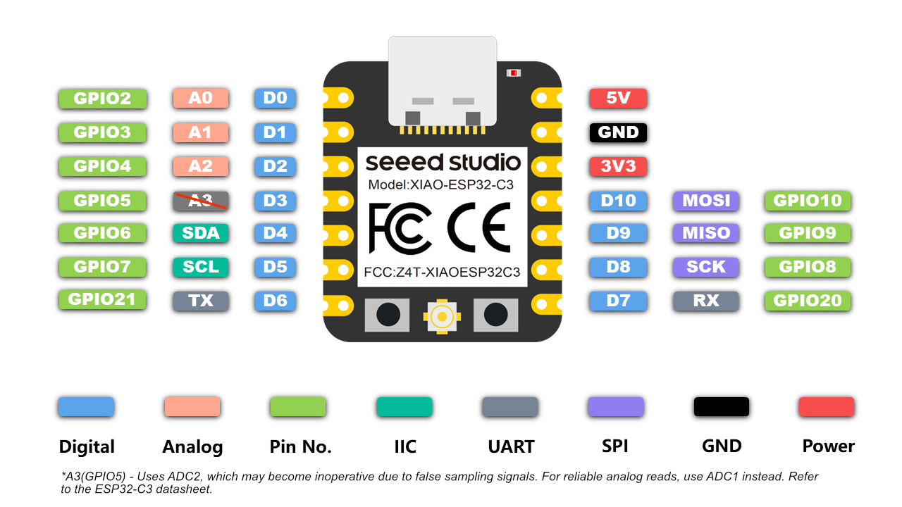
- Solderable. The ESP32 itself has teeny tiny pins too small to solder easily.
- USB-C port. I'm going to use this a lot. (Apparently the ESP32 doesn't have "native" USB? I'm not sure how much that will matter, guess I'll find out.)
- Buttons. One "Reset", one "Boot". Not sure what the Boot is for, guess I'll find out.
- Built-in "Charge" LED. I thought Neil said these also had a multicolor Neopixel LED, but according to the datasheet that's a feature only on the RP2040 version of the chip.
- Hmm, the Getting Started page says that this chip can only do Arduino, not CircuitPython, but there's a CircuitPython download page for the board, so that's weird. (Spoiler alert: I should have paid attention to this!)
- Wireless antenna. The board comes with a teeny tiny socket and a little patch antenna.
Comparing Development Workflows
Since I'm going to be teaching this class in the future, I decided it was worthwile to compare several development systems, to find out what's best to recommend to my students. Here's a summary table of the processors and development environments I worked with, with links to my methodology and a brief statement of problems I encountered.| Arduino Uno Rev3 | Seeed Studio XIAO-ESP32 | Seeed Studio XIAO-SAMD21C | |
|---|---|---|---|
| Arduino IDE | Success (group work) | Success | Success |
| CircuitPython | Incompatible | Failed | Success |
Basic Arduino development for the ESP32C
To set up the Xiao ESP32C for use with Arduino, I followed the Seeed Studios Getting Started with XIAO ESP32C3. Specifically I did the following:- Download, install, and launch the Arduino IDE.
- Add the ESP32 board package. In File/Preferences, add this text to "Additional Boards Manager URLs":
https://raw.githubusercontent.com/espressif/arduino-esp32/gh-pages/package_esp32_dev_index.json - In Tools / Board / Boards Manager..., search for "esp32" and install the latest version.
- Select your board and port. In Tools/Board/ESP32 Arduino, select XIAO_ESP32C3. (This didn't appear for me because I had an old version of the ESP32 library already installed. Letting Arduino "Update Boards" fixed it. The Xiao is waaaaay down near the bottom.
- In Windows, on the main window, choose "XIAO_ESP32C3 (COM##)" from the dropdown. In Windows the COM number identifies the serial port, it could be anything.
- Run a blink sketch. Copy the code below to an empty Arduino window:
Save this as "xiao-esp32-blink.ino".
// define led according to pin diagram int led = D10; void setup() { // initialize digital pin led as an output pinMode(led, OUTPUT); } void loop() { digitalWrite(led, HIGH); // turn the LED on delay(1000); // wait for a second digitalWrite(led, LOW); // turn the LED off delay(1000); // wait for a second } - Click "upload" to upload this to the board.
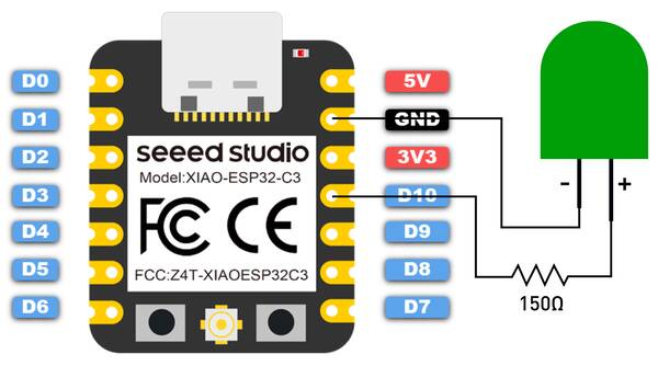
- Wire an LED and a 220 ohm resistor in series, from the D10 digital pin to ground, as shown in the diagram below.
- The LED should blink once a second.
Basic CircuitPython development for the ESP32C (Failed)
I tried to set up the Xiao ESP32C for use with CircuitPython, and had trouble. (I'm giving a brief summary here rather than a detailed procedure, because my steps won't help anyone.) I followed these instructions for installing CircuitPython onto the ESP32C. It was fairly complicated, but in theory it only has to be done once.Next I installed the tools we need to start writing code for the board. I downloaded, installed, and launch the mu editor. Then I switched into CircuitPython mode in mu. Here's where things went wrong: mu failed to recognize the Xiao as an ESP32 device.Apparently the C3 version of the ESP32 doesn't have native USB support, which is something CircuitPython more or less relies on. I also tried MicroPython but that didn't work either. Looks like if I want to use an ESP32, I have to use either Arduino or Espressif's own development toolchain.
Basic Arduino development for the SAMD21C
Since I really want to try out CircuitPython, I switched to the Xiao Seeeduino SAMD21C, which is based on the ATSAMD21G18A-MU processor. To set up this board for use with Arduino, I followed the directions on Seeed's site:
- Download, install, and launch the Arduino IDE.
- Open the Blink sketch from
File / Examples / 01. Basics - Add the SAMD21C board package. In File/Preferences, add this text to "Additional Boards Manager URLs":
https://files.seeedstudio.com/arduino/package_seeeduino_boards_index.json - In Tools / Board / Boards Manager..., search for "Seeed SAMD" and install the latest version of "Seeed SAMD Boards".
- Select your board and port. In Tools/Board/Seeed SAMD board, select "SEEED XIAO".
- In Tools / Port, choose "COM## (Seeeduino Xiao)" from the dropdown. In Windows the COM number identifies the serial port, it could be anything.
- From File / Examples, open the standard Blink sketch and compile and upload it. The builtin LED should blink once per second.
But what did fix the problem was this advice, which says that many of these chips can be forced to listen to the PC by double-tapping the reset button. The orange light should start glowing solidly. This is contrary to Seeed's advice, which is to do a single-tap. There's also the problem that the Xiao board doesn't actually have a reset button: instead it has two metal pads that you short together with a piece of wire (see image at right).
With a double-tap reset, the Seeeduino resets into "Direct Firmware Uploader" (DFU) mode: it reconnects to the PC and looks like a flash drive. It also will actually listen to programming requests from Arduino over the COM port. Two annoyances: Windows asks me what to do with this "new disk drive" every time I upload, and bizarrely, programming the Arduino briefly disconnects my USB headset, which I don't understand but doesn't do any harm. From here Arduino programming works normally, as described above.
Basic CircuitPython development for the SAMD21C
And now let's try out CircuitPython. Seeed has detailed instructions on setting this up, which is always a good sign.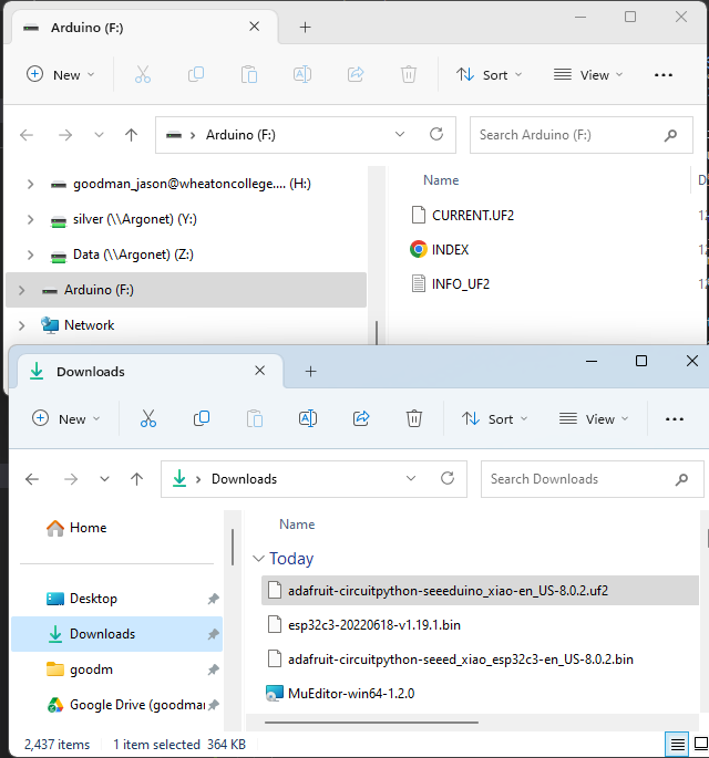
- Download the CircuitPython environment for the Seeed Xiao SAMD21. This downloads a .UF2 firmware file.
- Plug the Xiao into your computer with a USB-C cable.
- Use a piece of wire to connect the Reset pads on the board twice. A gif of the process is shown above.
- A new external drive named "Arduino" should appear in Windows Explorer or Mac Finder. Drag the .UF2 file you downloaded into this drive. Wow that's easy!
- The Xiao should reset, and a new different external drive called CIRCUITPY should appear. You can program the Xiao by creating and editing a Python program called "
code.py" into this drive. For example, here's Seeed Studios' Python equivalent of the Arduino "Blink" sketch: - CircuitPython will automatically restart the Xiao and run your
code.pyprogram every time you save it. But if it doesn't, you can "eject" the CIRCUITPY "disk", and it will re-run. - Another great feature of CircuitPython is that serial communication is done just using "
print()" statements, and at any time you can halt execution of your program by typing control-c into the serial monitor, which drops you into a REPL (Read-Evaluate-Print Loop), so you can write code interactively!
import time
import board
from digitalio import DigitalInOut, Direction

led = DigitalInOut(board.LED_INVERTED)
led.direction = Direction.OUTPUT

while True:
    led.value = True
    time.sleep(1)
    led.value = False
    time.sleep(1)
Using the Mu editor with CircuitPython
While you can program a CircuitPython board just by saving a file created in any editor, the "Mu" editor has some handy special features that let you talk to the Xiao in real time. To set it up:- Plug in your CircuitPython Xiao. It should appear as a "CIRCUITPY" external drive.
- Download and install the Mu editor. Start it up: the first time it starts, it will take a long time to get ready, but after that it's quick.
- Choose "CircuitPython" mode. Mu should automatically detect your Xiao board, and show a non-crossed-out computer chip in the bottom right corner. If it's crossed out, you'll get an error saying the Xiao wasn't found: this means you should reinstall CircuitPython.
- Mu is designed to work with CircuitPython's "reboot with every save" mechanic, and provides access to a serial monitor just like Arduino.
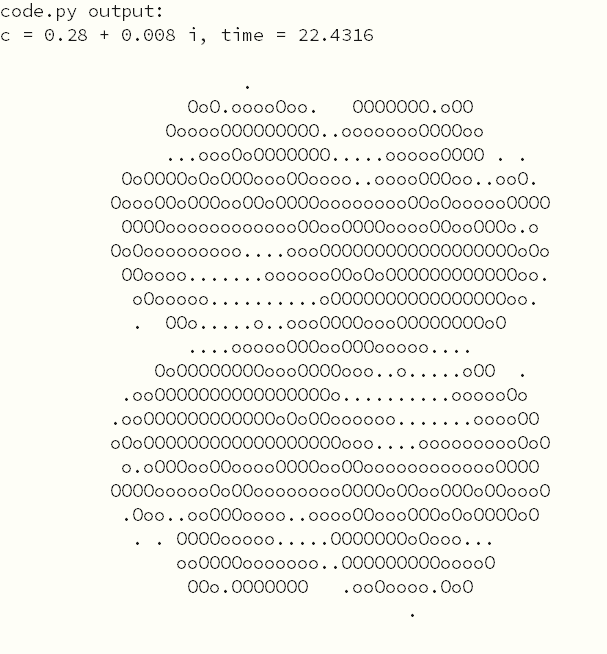
Joystick Julia
I wanted to create something that satisfies the homework requirements for this week (program a microcontroller development board to interact (with local input &/or output) and communicate (remotely)) that would give me some insight about floating-point math on current-generation microcontrollers. So I wrote some code to generate Julia set fractals based on joystick input and print them out over the serial port.
How do you do computer graphics over a serial port? I used a simple text-based system, where " ", ".", "o" and "O" represent increasing "brightness".
I used "spiral design" to build this. First I just created a Julia set generator with no electronic inputs, just serial port output, and tested this in both CircuitPython and Arduino. CircuitPython was too slow to be useful. Then I added the joystick and the code to interact with it, writing my final version for Arduino only.
About Julia Sets
Julia sets are a type of fractal closely related to the famous Mandelbrot set. They are generated using the following algorithm:- Pick a number \(c\) in the complex plane.
- For all numbers \(z\) in the complex plane,
- Calculate a new \(z = z^2+c\)
- Repeat, iterating over and over.
- If \(z\) heads off to infinity, it is not a member of the Julia set. If it doesn't, it is.
- Plot the values of \(z\) that do or don't head off to infinity on the complex plane. Typically the number of iterations before each point "runs away" is shown with a color map.
Raw CircuitPython on SAMD21C
First, a CircuitPython version of the basic Julia generator with no joystick input. (source code is found in my repo). It doesn't use any special libraries, and has functions to do math on complex numbers. I didn't bother with classes, my complex numbers are just 2-element arrays.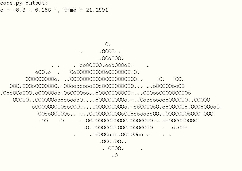


Arduino on SAMD21C
Next, an Arduino version of the basic Julia generator with no joystick input. (source code in repo). This runs about 20 times faster than the CircuitPython version!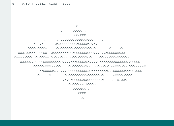
CircuitPython with ulab (Failed)
Python is, as expected, extremely slow. In desktop python, there's a "numpy" module which is designed to make math operations fast and easy. In CircuitPython, this is implemented using the "ulab library. I tried to get this working, but it looks like ulab is not installed in the SAMD21C version of CircuitPython. It's possible to recompile the CircuitPython firmware to include it, but that's more of a pain than I have time for right now.This leaves us in an awkward position: for my final project, I need ulab and CircuitPython. CircuitPython won't run easily on the ESP32 processor, ulab is difficult to set up on the SAMD21C, and it looks like the SAMD21C might be too slow anyway. Conclusion: I think I need the RP2040 version of the Xiao!
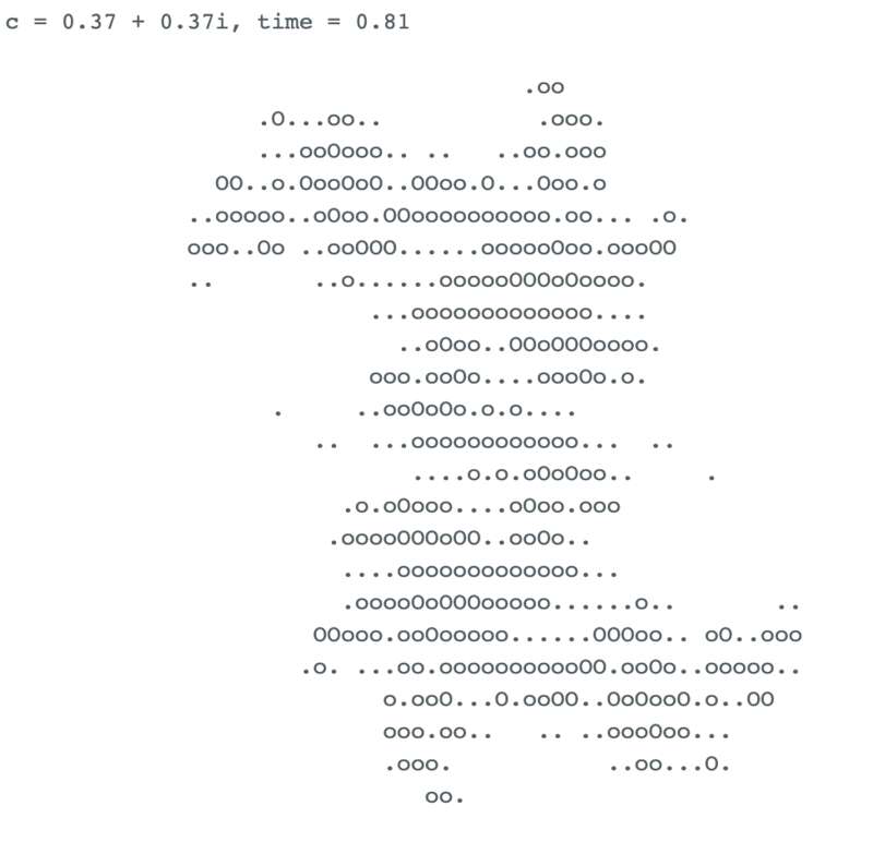
Final version with joystick control
 Finally, we add joystick input to allow the user to select a value of \(c\). This is, of course, a ridiculous input method: nobody would do this unless it was for an assignment that has to both "interact" and "communicate". But it ended up being pretty fun!
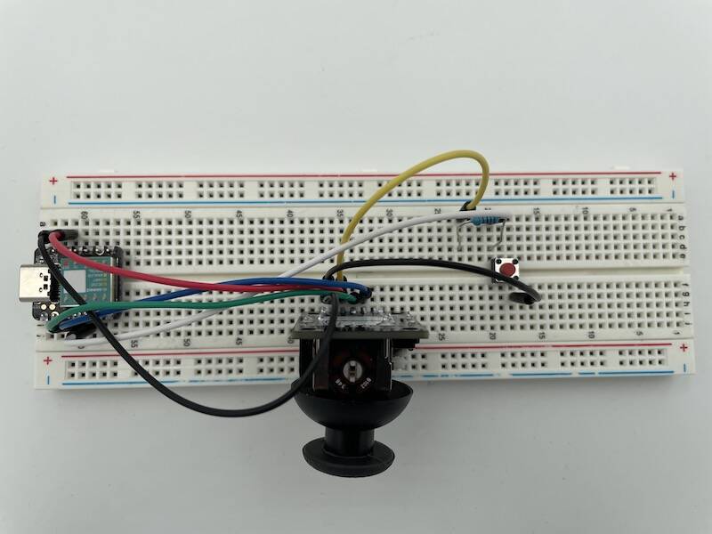
Here's the circuit diagram for the joystick and button. The joystick is just a pair of potentiometers in a convenient package. I used a separate button rather than relying on the "push to click" feature of the joystick, because pushing in on it always messes up my aim.
I also took the time to fine-tune the "brightness values", to get more detail with my ".oO"-based graphics system. See the video below!
Of course this would be much better with an LCD touchscreen. Or just as a mobile phone app. Frankly, doing text-based graphics for a fractal image with joystick input is pretty ridiculous. But it satisfies the homework requirement, it taught me a lot about the tools I'll need for my final project, and I think it's pretty neat.
Design Files
- julia_arduino.ino (Basic Julia set creation with Arduino)
- julia-circuitpy.py (Basic Julia set creation with CircuitPython)
- joystick_test.ino (Test joystick operation)
- joystick_julia.ino (Final Joystick Julia code)