      individual assignment:
         measure something: add a sensor to a microcontroller board
         that you have designed and read it
      group assignment:
         probe an input device's analog levels and digital signals
Group Work
Our group work is documented here. I've worked with these sorts of sensors before, so I didn't get a lot of new insights from the group assignment, but I enjoyed helping my fellow students learn.Sensing magnetic fields with the TMAG5273
My plan for this week is to gain familiarity with the TMAG5273, the Hall effect magnetic field sensor that I'm hoping to use for my final project. Key features of this sensor that will be important for my project are:- 3-axis field sensing
- 12-bit resolution
- Can sense very strong fields (up to 266 millitesla)
- Able to sense very weak fields (down to 1 microtesla?)
- Comes in 4 identical models with different built-in I2C addresses
- I2C addresses are software-reprogrammable
- Hand-soldering-friendly SOT-23 package
I was able to find an Arduino library by TuYuxiao for this device, but if that doesn't work I'm prepared to write my own.
For the final project, I'll need to talk to at least 16 of these devices at once. I spent some time getting cuddly with the TMAG5273 datasheet, and learned a little about how to talk to lots of them at once. Each one either needs a unique I2C address, or needs to be on a separate I2C bus. The good news is the Xiao RP2040 has two easy-to-use I2C buses, and the TMAG5273 comes in four varieties, which are identical except for the I2C address. But that only gets me a total of eight. But even better, the sensor allows you to reprogram its I2C address. But that's a project for another week; this week I just need to get one or two going.
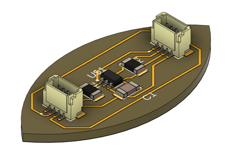
Board DesignI wanted to continue my leafy "Beansprout" motif with Qwiic sockets for the TMAG board, so I can plug it into my Beansprout dev board. The TMAG5273 is a pretty simple device, it just needs a power supply capacitor, two pullup resistors for the I2C lines, and power.
This week, I decided to try out Autodesk Fusion 360's Electronics Design workspace to develop this board. The really nice thing about Fusion Electronics is it makes it easy to integrate circuit board design with the mechanical design of the rest of the project. You can sketch a circuit board in the 3-D design workspace, hop into Electronics, add a schematic and a board layout, then hop back into the design workspace and see a 3-d model of your board. You can line up buttons and displays so they work mechanically, and then hop back into the board layout to run the traces. It's pretty slick!
The bad thing about Fusion Electronics is ... everything else. I found it generally more frustrating to use than KiCAD, and that's saying something. I don't have time to explain every step of my design process in microscopic detail, but here are some of the key skills and methods I used to create my TMAG board:
Creating a PCB
Creating a new PCB with a custom shape is easy in Fusion: just draw a sketch in the Design workspace and choose "Create / Create Associative PCB". A new set of board design files will be created, and the outline of the board is linked to your sketch.Importing Eagle Libraries into Fusion Electronics
Fusion 360 Electronics is basically a rebadged Eagle, and it accepts Eagle electronics libraries. For this project, I used the Fab Academy Eagle library, I downloaded a library for the JST connectors I was using, and created a parts libraries for the TMAG5273 sensor manually. To add a new library:- In the Library tab for the Schematic editor, choose "Open Library manager".
- Click the "Import Libraries" icon at the top right corner of the main window. This lets you pick a library from your local disk, or within the Fusion project. Fusion likes to store its libraries in the cloud, best to just let it do its thing.
Creating Custom Footprints and 3D Models in Fusion Electronics
Fusion has a nice feature that lets you "easily" create and add new component symbols, footprints and 3D models to a library. I'll show the steps I used to add the TMAG5273 part to my project: the other parts work similarly.- In the Library Manager, choose "Edit Library"
- First, create a new Component. This holds all the info about the part.
- Next, select the component and choose New Symbol.
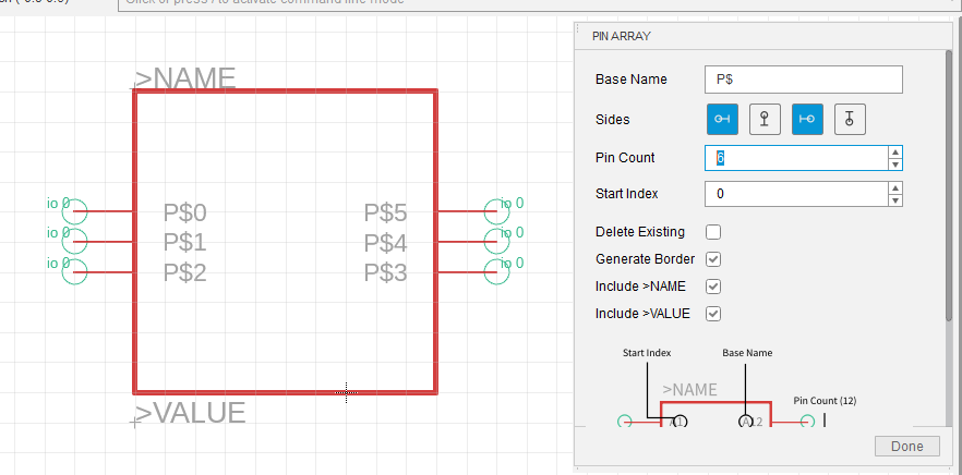
- Draw whatever shape you like, but use the Place Pins feature -- or better, Pin Array -- to add pins. Then use the Place / Name command to give them meaningful names (SDA, GND, etc), using the datasheet.
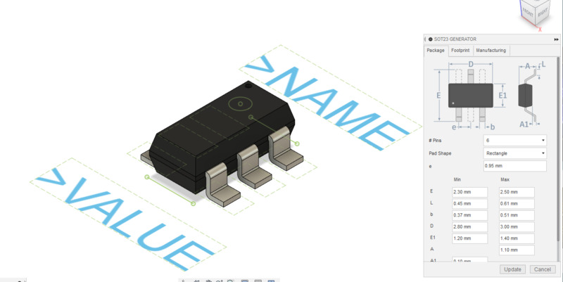
- Next, select the component in the library and choose "New Package". A 3-d modeling window will pop up, you could design the package yourself, but Fusion has a built-in package generator. For the TMAG5273, i told it to build a 6-pin SOT-23 package and checked the dimensions against the datasheet, and pop! Instantly created. You can also import 3-d model files downloaded from the web, which is what I did for the JST connectors.
- Here's where it gets confusing. You now need to Add a Device to put the symbol you made into the component you made.
- Plop down the device, and you'll see a side panel that lets you pick a Package to the Component. (Components can come in a variety of different packages.) Choose New / Add Local Package. Choose the package you created earlier.
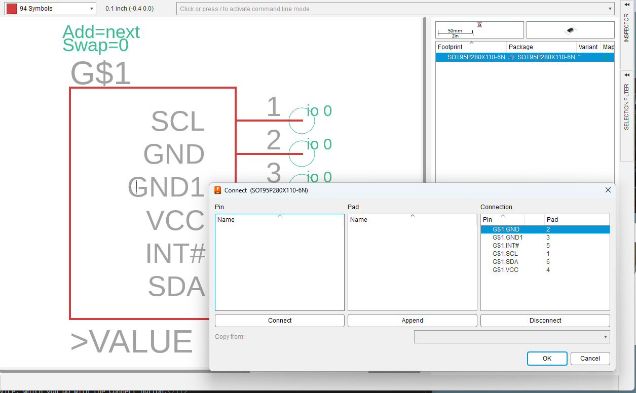
- Finally, you need to tell Fusion which pins on the symbol correspond to which pads on the device, which you do with the Connect button.
Creating CAM output files for MODS in Fusion Electronics
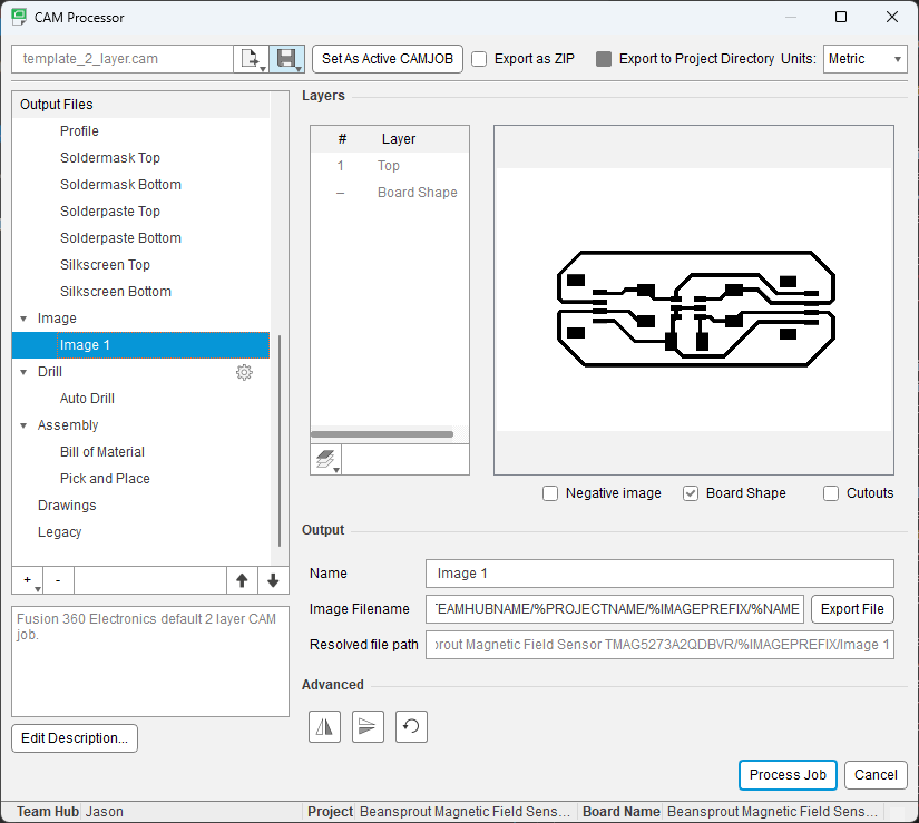
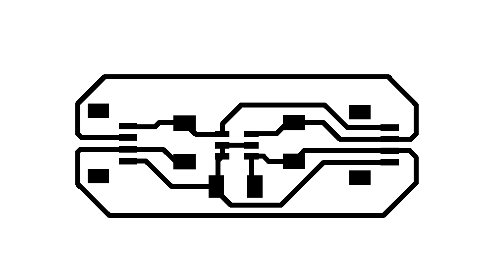
To convert a Fusion 360 electronics board file into a PNG image for use with MIT MODS, choose "Manufacturing" the tab in the command ribbon. Select "CAM Processor" and delete all the manufacturing rules for ODB++, Gerber, and so on. In the Image output file config, set "Output Type" to "PNG". Right-click on "Image" to create a "New Image File". Do this twice, once to create an image containing only the board shape, once to create a traces image using the Top layer. "Process Job" to create the images. They're mandatory 600 dpi, which is fine, and you'll have to fill in the inside of the outline image with black using a paint program. (And in MODS, you'll need to invert the black and white for both traces and outline.)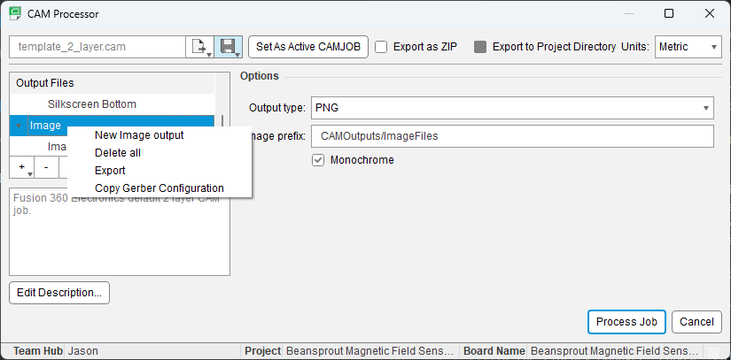
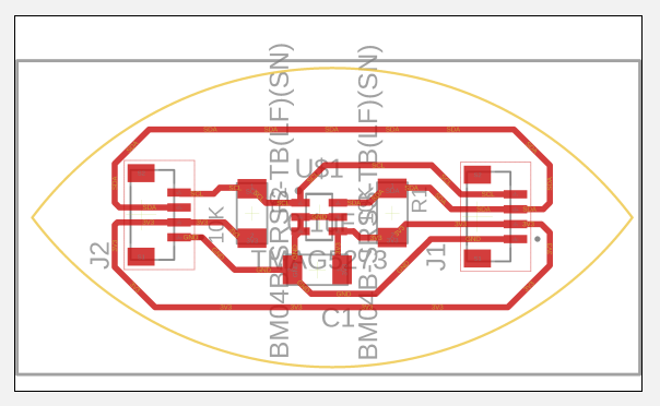
Fusion Electronics Results
Here are my final design results for the TMAG daughter board: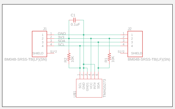

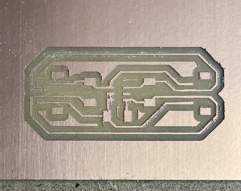
Manufacturing
Actually manufacturing the board was more straightforward, I followed the same steps described in my Week 08 documentation. I ran into two minor problems and one big one while manufacturing. The two minor ones:- My Sainsmart mill didn't give really crisp traces on the milled board. I eventually traced this down to bad workholding: I was using some new thin Scotch brand double-stick tape, which isn't as strong as the carpet tape I've used in the past. I solved this by using clamps aggressively.
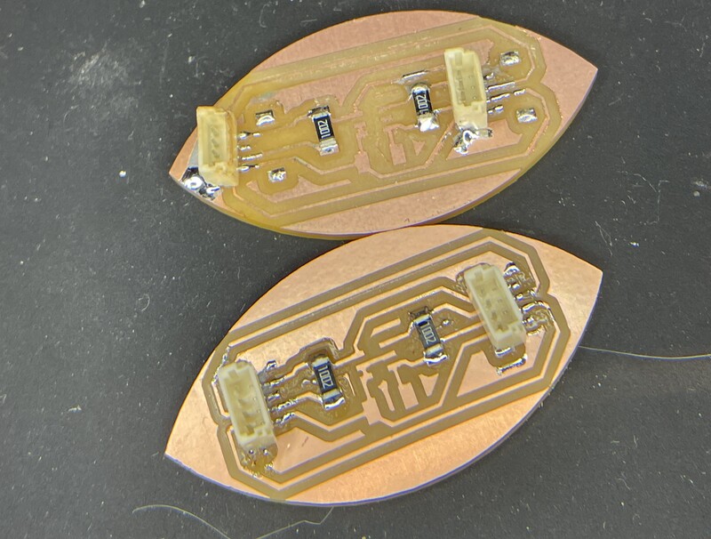
- The SOT23 package the TMAG5273 comes in is pretty hard to solder. Doable, but not much fun.
The big problem: As I was soldering, I realized that I got the pin order backwards on the JST connectors. They're in the reverse order of the Qwiic specification, and backwards from by Beansprout board. I solved this problem two ways. As a jury-rig, I unsoldered the JST connectors and flipped them around on the board. This means that their anchor pads aren't very well attached, so they could break free, and also resoldering was really difficult. So I also redesigned the board and milled a new one, with the correct layout. In the end I got both working, which is great because I want to test two at once.
Programming
To program the board, I started with example code using the TuYuxiao TMAG5273 library. I spent a few hours trying to get it to work: it turned out that the JST connectors on my original Beansprout devboard were cold-soldered, and while they worked when I tested them a few weeks ago, they didn't last. I re-did the soldering and fixed that. Eventually I was able to get the prepackaged demo to work (no screenshots, I'm afraid.)
Two I2C ports
Since I'm going to be using a lot of these sensors, I want to be able to talk to them using lots of I2C ports. The RP2040 has two separate I2C interfaces, which can be assigned to different pin numbers. My Beansprout board has two JST sockets, one for each I2C interface. Or at least that's what I intended.
I rewrote the example code to show the data from two sensors at once, but I wasn't able to get the RP2040 to talk to the second TMAG5273 on the secondary I2C port. After quite a few hours of struggling and reading the RP2040 datasheet, I figured out the problem. While each I2C interface can connect to a wide range of pins, they can't connect to any pin. When designing the board, I didn't realize that I2C0 can only connect to half of the GPIO pins on the chip, and I2C1 connects to the other half (See Table 2.19.2. of the RP2040 datasheet.) And by bad luck, the pins I chose for the two I2C ports are both tied to the chip's I2C0 interface. So there's no way to do double-I2C without redesigning the Beansprout dev board. Crap.
The annoying thing is that I actually checked this when designing the Beansprout, but the Xiao is set up to use "I2C1" as its standard I2C interface, and "I2C0" is the alternate "Wire1" interface. Anyway, if you're confused so am I, everything's backwards. Here's a table:
| Beansprout pin | Xiao pin | RP2040 pin | RP2040 I2C role |
|---|---|---|---|
| First I2C SDA | D4 | P6 | I2C1 SDA |
| First I2C SCL | D5 | P7 | I2C1 SCL |
| Second I2C SDA | D2 | P28 | I2C1 SDA! |
| Second I2C SCL | D3 | P29 | I2C1 SCL! |
| Second I2C SDA (Revised) | D6 | P0 | I2C0 SDA |
| Second I2C SCL (Revised) | D7 | P1 | I2C0 SCL |
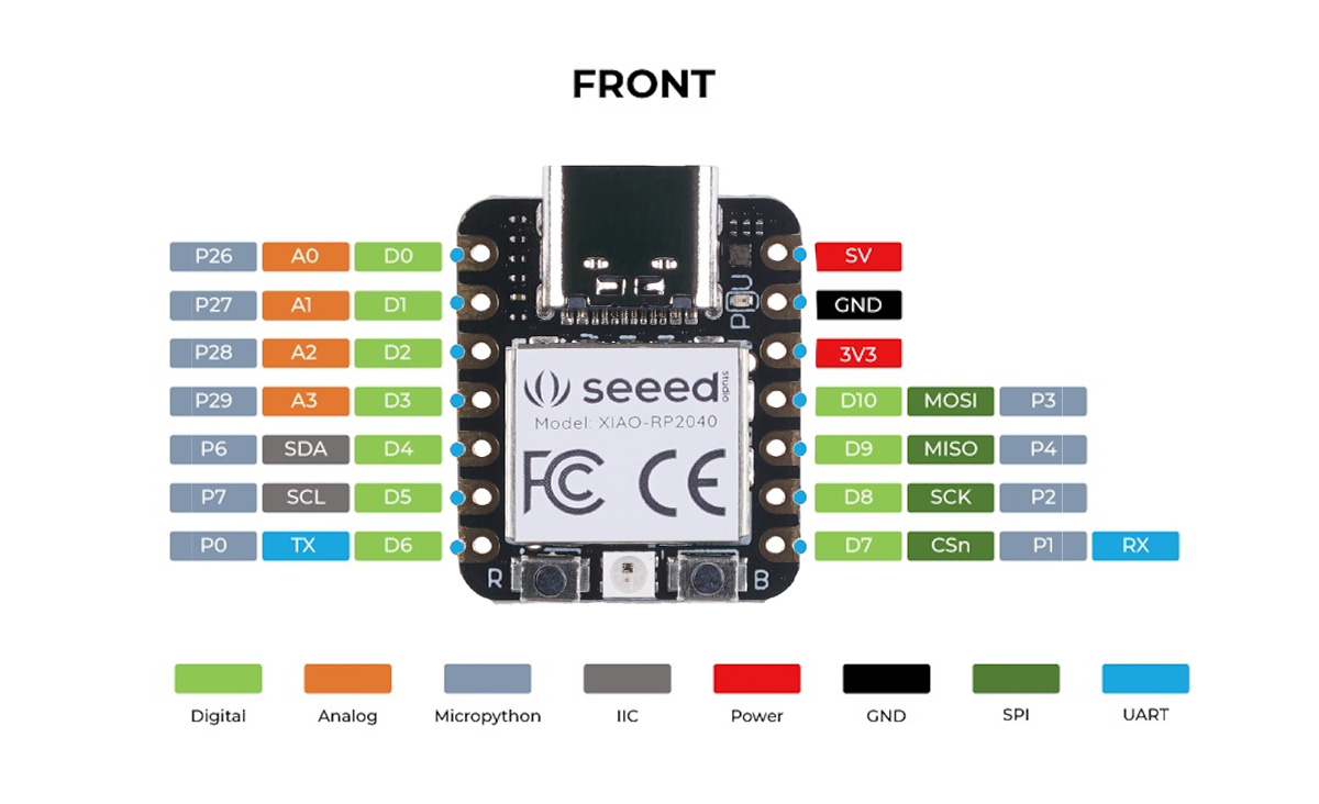
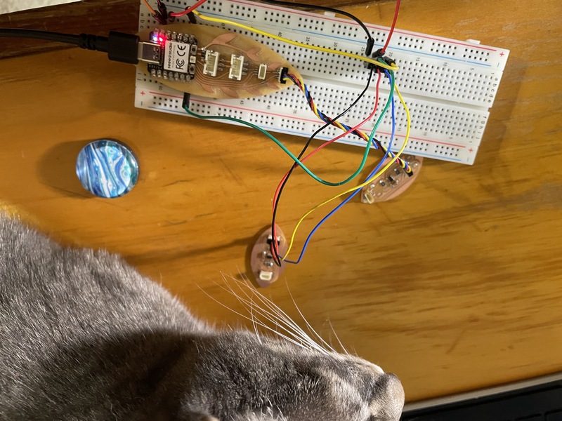
Fortunately, I designed the Beansprout so all the Xiao's pins are exposed on the bottom, so I can plug it into a breadboard. I wired up my second TMAG5273 to Xiao pins D6 and D7, which connect to the RP2040's alternate I2C interface, and was able to get both sensors working at the same time. See the photo and video below.
Next Steps
The obvious next step is to wire up the TFT display and show the output from the magnetic field sensors graphically on it. But I'm out of time for this week, so this will have to be enough for now.Design Files
- Beansprout TMAG5273 module - Design Files (Fusion 360 Archive file)
- Beansprout TMAG5273 module - traces
- Beansprout TMAG5273 module - outline
- TMAG5273_basic_rp2040.ino -- basic magnetic field example code
- TMAG5273_basic_rp2040_twoi2c.ino -- Two magnetic field sensors working together on different i2c ports.