Week 02: Input Devices (Group work)
Neil's assignment:
group assignment:
  probe an input device's analog levels and digital signals
Measuring Analog Inputs
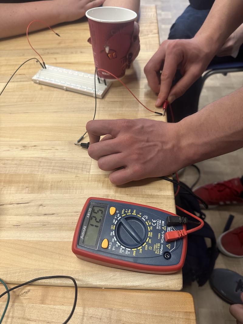
For our group work, we investigated the behavior of a thermistor and a 10K NTC thermistor by simply measuring their resistance using an ohmmeter.

NTC thermistor
NTC stands for "negative temperature coefficient", which means that as the temperature rises, the resistance of the thermistor goes up. We connected the thermistor to our meter, set the meter to 200K resistance range, and measured the resistance under the following conditions:
| Held in fingers | 6.3 K |
| Ambient room air | 9.2 K |
| Touching a cup of cold water | 12.6 K |
| Touching an ice cream package | 16.3 K |
Indeed, as the temperature increases, the resistance goes down.
Photoresistor
We performed a similar experiment using a photoresistor (exact type unknown). This time we varied the light level in the room.
| Illuminated with iPhone flashlight | 0.15 K |
| Ambient light | 1.5 K |
| Completely covered with hands | 10 K |
In this case, the resistance decreases as the light level increases.

Using switches to create digital signals
We also learned how to correctly wire buttons and sensors to create digital and analog signals to input into a microcontroller.
Digital Circuit
Digital on/off devices like switches and buttons should be wired with a "pull-up" or "pull-down" resistor as shown in the digram at right. The "TO_MICRO" line connects to a digital input pin on the microcontroller. The resistor ensures that the digital input line is pulled down to ground when the switch is disconnected.

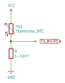
Analog Circuit
Analog devices that vary their resistance, like our photoresistor and thermistor, should be connected in a circuit like the one shown at right. This is a "voltage divider": the voltage at the "TO_MICRO" connection varies depending on the resistance of the sensor in a mathematically predictable way. For best results, the fixed resistor should have a resistance similar to the resistive sensor.


