Group Memebers
Our CNC Machine
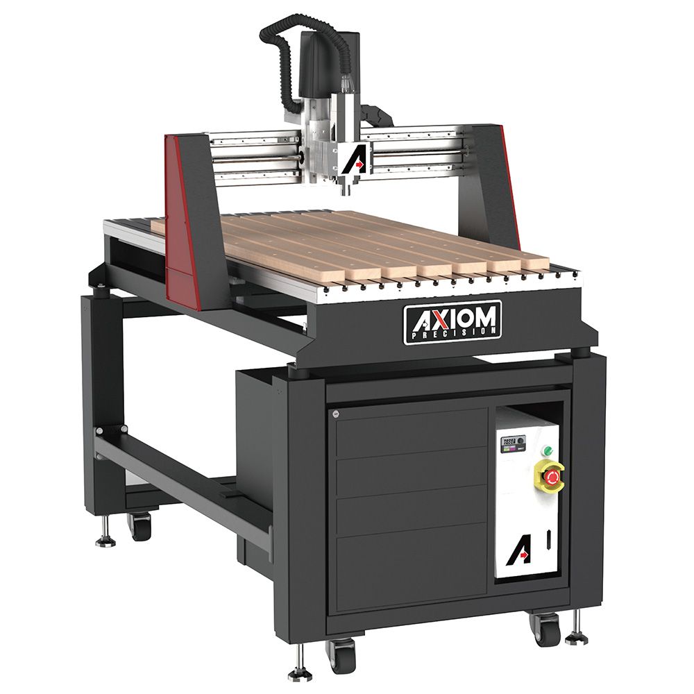
For this group assignment, we used our lab's Axiom Iconic-8 24 x 48 3-axis CNC machine. This machine is capable of cutting wood and other soft materials up to 24 by 48 inches across, and around 3/4 inches thick. We learned how to use the Vcarve software to generate toolpaths for it, though it can also be driven by Fusion 360 or other software.
Definitions for this week
- CNC: Computer Numerical Control
- End Mill: A cutting bit used for milling
- Flute: A channel on an end mill to direct the cutting debris
- Runout: When the End Mill doesn’t spin perfectly on its center axis, it wobbles and results in runout
- Spoil Board: The board on top of the machine bed that is made to protect the bed from the end mill cutting through your material
- Alignment: Levelness and straightness of the spoil board
- Fixturing: How we hold the material to be cut on the bed
- Toolpath: The path that the endmill follows to cut the material
- Tabs: Small Sections of Material that the machine avoids to hold material in place when cutting through the entire thickness of stock
Toolpath creation in Vcarve
To create the toolpath for the router, our instructor Brandon used Vcarve. The process went roughly as follows:
1: Import files into Vcarve, we used .dxf files.
2: Set the thickness of your material in material setup
3: Select the profiles of your sketch and add appropriate toolpaths.
- We used a profile toolpath to cut out the shape and the holes. For the outer perimeter we set the machine vectors to outside/right, and for the holes inside/left. For both of these we added tabs in a few places to hold the work in place. Tabs can be added by checking [Add Tabs to Toolpath], and then clicking on the vector lines where you wish to add tabs.
- We used a pocketing toolpath for the indented areas, and set the depth of cut to something less than the material thickness.
4: Make sure to order the toolpaths such that the ones that remove the most structural stability occur last. For our job, this meant the pocket toolpath first, followed by the interior profile, then the exterior profile.
5: You can preview the cut with a button in the toolpath ordering sidebar. This will animate a simulation of the router following the toolpath. If the preview looks right, you can export the job and move it to the router.
Cutting Bits
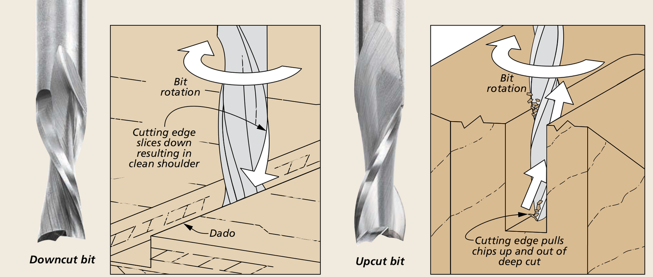
The machine can use a wide range of cutting bits, but we used two for our group exercise: a 1/4" flat downcut mill and a 1/4" flat upcut mill. Both cut a flat-bottomed slot 1/4" deep, the difference between them is the direction of their spiral teeth. The upcut bit pulls upward on the material as it turns, clearing sawdust from the hole. This can prevent jams and fires, but it can create splinters at the edge of the cut. The downcut bit pushes down on the material as it turns, which gives a cleaner edge and provides more force to keep the work in place, but you can only use it for cuts that give room for the sawdust to escape. We used the downcut bit for the "pocket" in our design, and the upcut mill for the other steps.
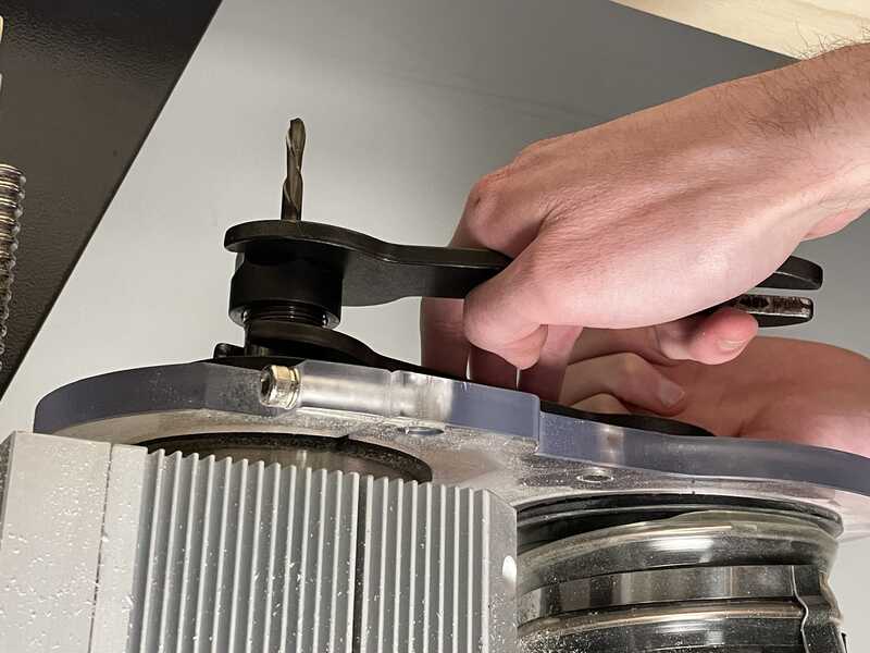
To change bits, the following steps are required.
- Make sure the hand controller is in a secure place so the machine doesn't start up while you're working.
- Put the small wrench on the flats of the cutting spindle's shaft.
- Put the big wrench on the collet nut. The big wrench should be just a little to the right (counterclockwise) of the little wrench.
- Squeeze the wrenches together with one hand. This should loosen the collet nut without pulling or pushing the CNC machine.
- Loosen the collet nut until the bit can be removed. No need to completely remove it.
- Install the new bit so that almost all of the shaft is inside the collet, but the cutting edges are outside. Tighten the collet nut by hand.
- Go back in with the wrenches, to finish tightening, but this time the big wrench should be to the left of the little one.
- Squeeze hard with one hand to tighten.
Machine Setup
To set up the machine, we first fixed a 17in*48in*0.5in board of pine wood on the machine bed using screws along the edges, making sure the board stays steady during the cutting process. We also changed the end mill of the machine using the procedure above, seleting a 1/4" downcut endmill to start.
Before starting the machine, we had to set the xy origin of the end mill to make sure the machine starts at the position we want it to start at. Using the x and y motion buttons on the CNC controller, we moved the end mill to the corner of the board to avoid middle cuts and material waste. However, we kept the end mill far enough from the corner screws because the end mill breaks if it cuts into a screw. Then, we pressed the xy <- 0 button to set the origin, that is, the zero xy-coordinates, of the end mill at that exact point.
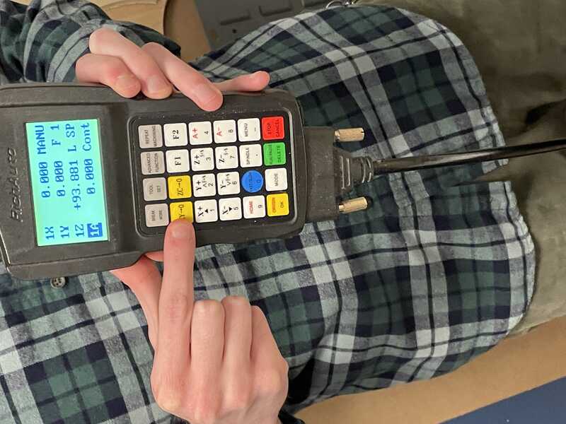
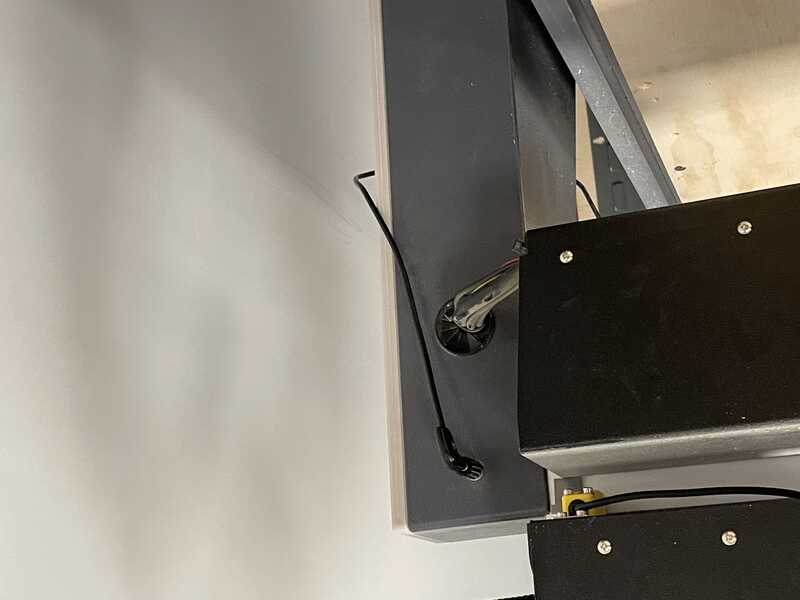
The next step was to z-level the end mill. This CNC machine uses a touch-off puck to be aware of its height above its bed. We first plugged the puck cable in a port at the side of the CNC machine and placed the puck below the end mill. Then, pressing the Tool Set button,, we moved the end mill down the z-axis till it touched the puck, creating a full circuit that caused the end mill to bounce upwards. As the machine program already knows the height of the puck, it now knows how far it is from the top of its bed.
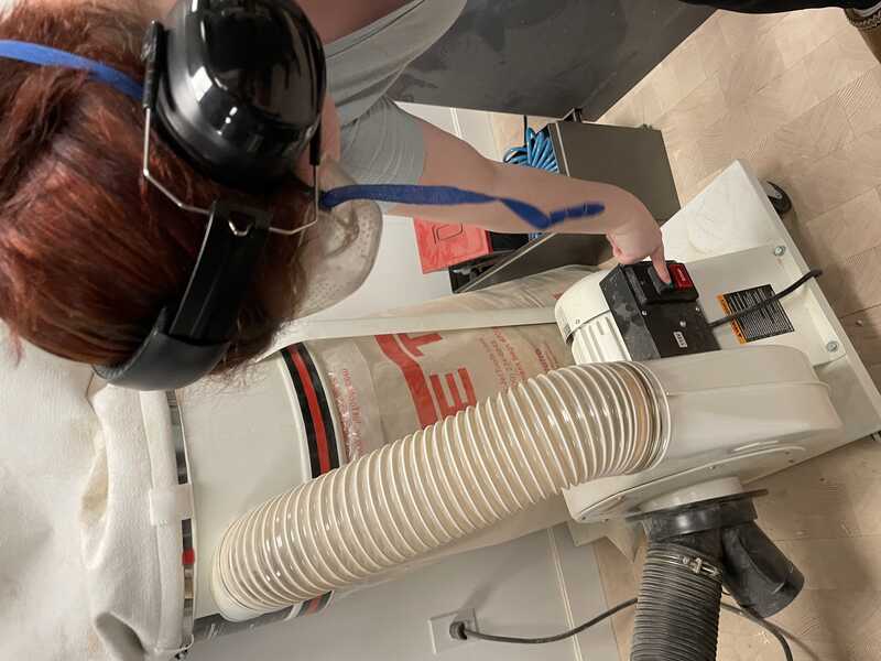
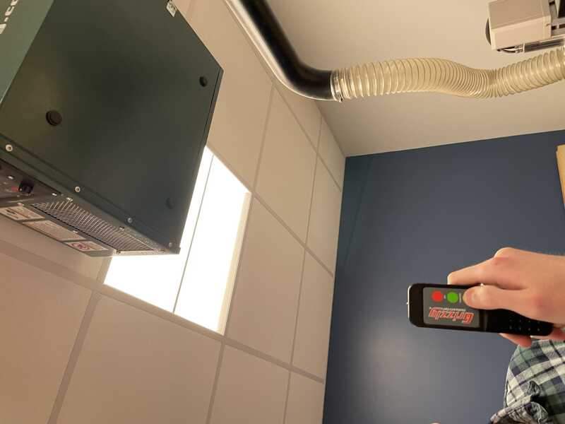
Now, as the machine was set up, we placed the dust cover brush which sticks magnetically around the end mill to prevent dust from escaping from the dust collector, which we turned on after that to suck all the dust caused by cutting. We also made sure to turn the room's ventilation on. Finally, we had to select our file from the USB disk we had uploaded our file to and then press the start button to start cutting.
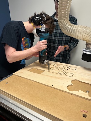
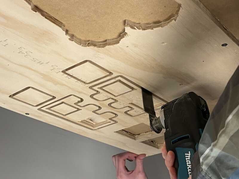
Cutting Tabs
In order to fully remove the design cut from the material, we had to cut the tabs that we made in Vcarve. Using an oscilatting tool with a saw blade attachment, cutting each tab freed the cuts from the excess material.
Measuring Difference
Finally, we measured the shapes we milled to see if they ended up the size that we planned them to be.
First we measured the 2 inch by 2 inch square that we cut out using a digital micrometer.
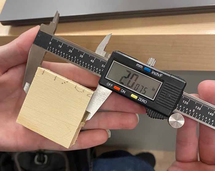
And as you can see, the output wasn’t exactly 2 by 2 but it is close enough for this test.
Next we measured the hole that was milled into the piece.
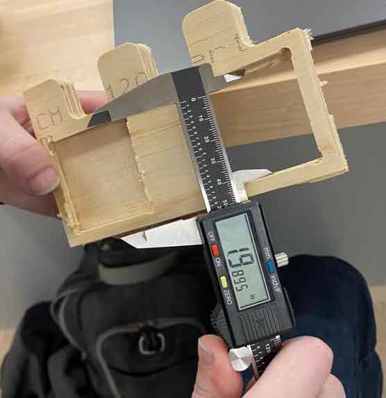
The square ended up being a little smaller that was expected so the earlier square piece wouldn’t fit into the hole as it should if it were the right size.
Conclusions
- After selecting the profiles of the sketch and setting the appropriate tool paths our machine we ended up cutting out the right lengths of the design. We did this by using the toolpath on the design to measure out the indented areas and the depth. .
-
When we were done with the sketch we used the downcut mill and the uppercut mill to help cut the holes of the model. We figured this out by knowing the downcut mill only cuts down to make holes while The upcut bit pulls upward on the material as it turns, clearing sawdust from the hole.
-
Then we set up the controller to the machine to set up where the mill is gonna be cutting. While we did these steps we made sure the machine was secure and safe by having no jewelery on while using the machine and watches. We also wore safety glass to protect our eyes and noise cancelling headphones because of how loud the machine was.