Magical Revolving Lantern Mechanism Design
According to my initial plan, the revolving lantern part needs to be motor-driven. After observing many 3D revolving lantern structure designs, I decided to try to create my own motion mechanism design.
Lantern Internal Support and Rotating Cage Structure Design
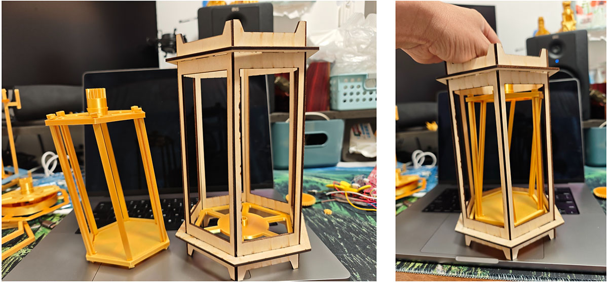
After completing Week 3's laser cutting assignment, I obtained the outer structure of the lantern assembled from thin wooden boards. Now I need to design a rotating internal structure for the lantern based on this foundation.
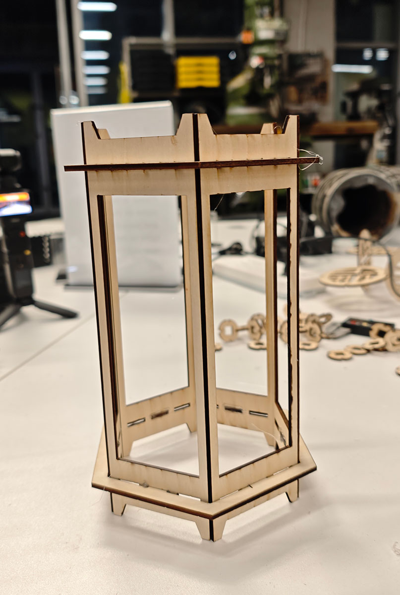
The assembled lantern shell looks very sturdy
Bottom Support Structure
Based on my Week 3 Fusion file, I first designed a bottom support structure and produced a version using a 3D printer. However, I found that the size was too large (I ignored the thickness of the 6 fence pieces), making it impossible to fit into the bottom frame.
The first design failed, as it was too large and could not be installed
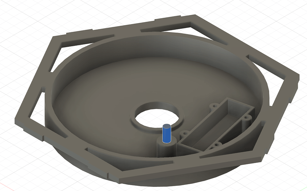
For the second attempt, I allowed for the thickness of the outer rails and readjusted the design. The Fusion design effect is shown in the figure below.
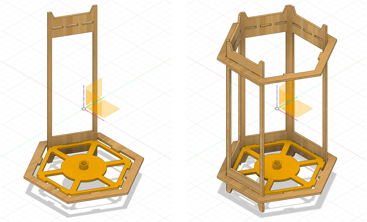
The modified second version of the bottom support structure design
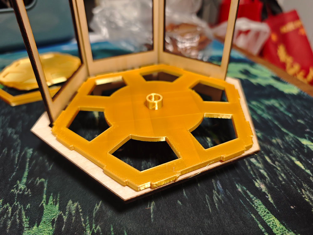
I output the design with 3D printing again, and this time it felt just right.
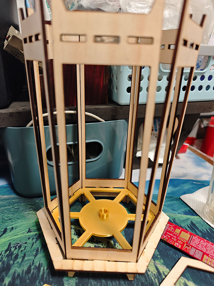
The second design of the bottom support structure feels appropriate
Lantern Rotating Cage Design
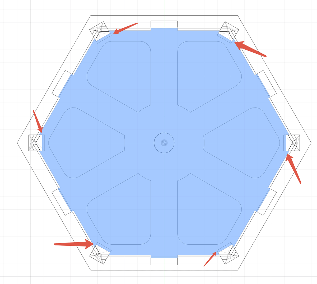
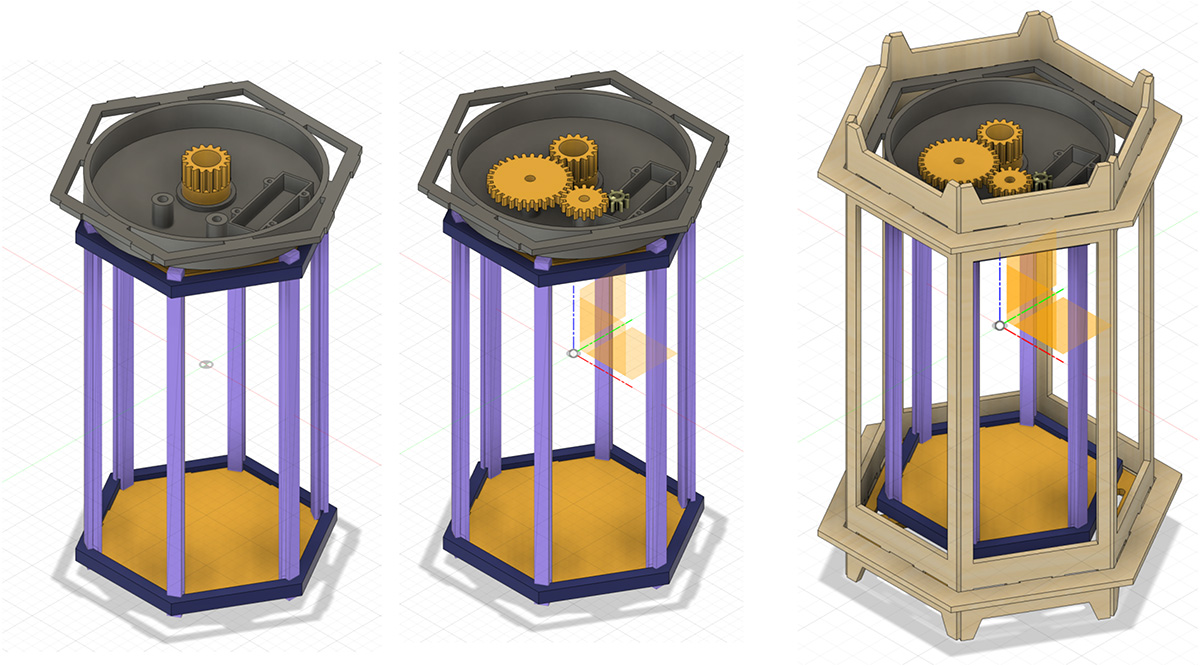
For the bottom of the lantern, I used a conical structure on the central axis that can be inserted into the cylindrical ring of the bottom support structure, allowing the rotating cage to turn easily. The structure is fixed with 6 rotating cage columns.
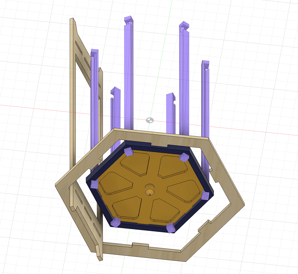
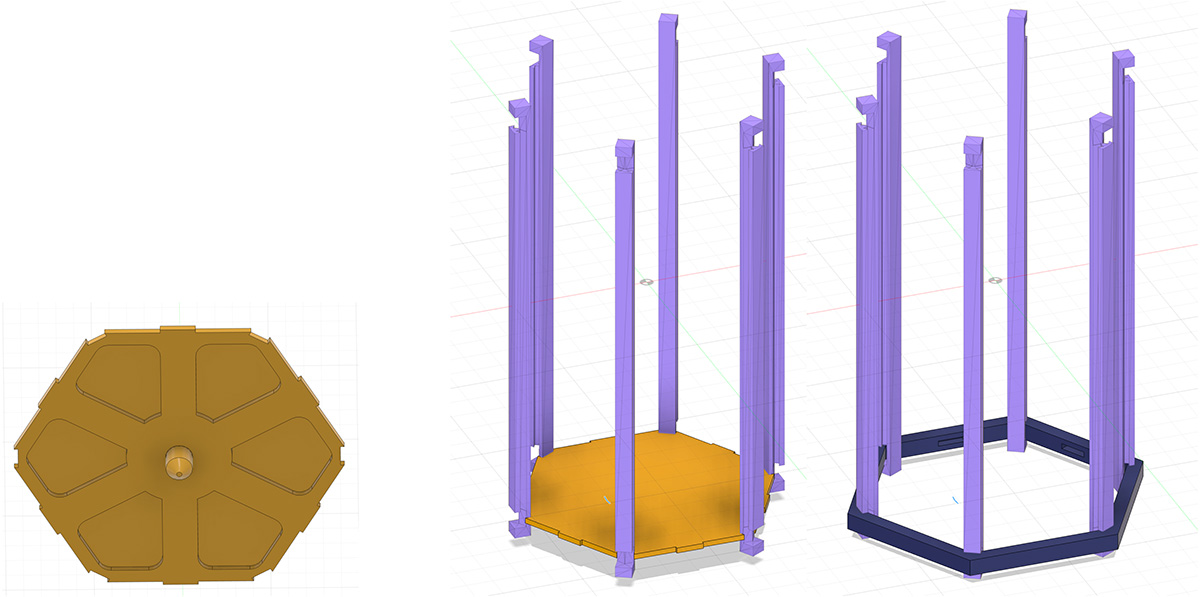
The bottom of the rotating cage is divided into 2 parts: a yellow base plate with a cone and a blue outer frame. After nesting together, they can lock the 6 rotating cage columns
For the upper part of the rotating cage, I used a blue outer frame of the same size, and made a hole in the center of the top cover, along with a shaft with gears. I plan to use the hole in the middle for threading the light strip.
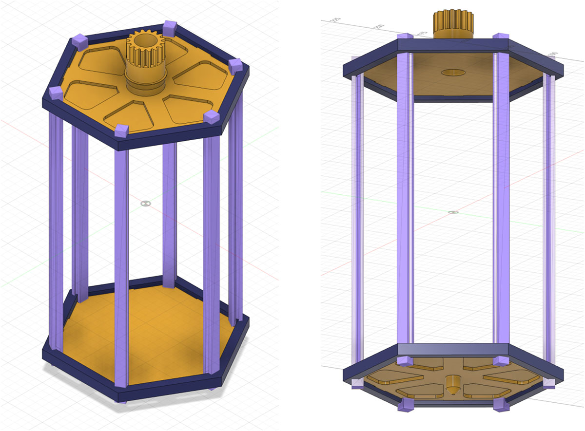
The top cover of the rotating cage has a hole and a shaft with gears
After designing the entire structure, I exported the STL files and 3D printed these 10 parts for assembly. However, I found that the gaps between the top and bottom covers and the 6 columns were too large (1mm extra), causing the columns and covers to fail to support and fix each other. The entire rotating cage was tilted to the point that it couldn't even rotate when placed on the bottom support board.
The gaps between the top and bottom covers and the 6 columns of the rotating cage were too large, making the entire structure too loose to use
I expanded the gap from the top and bottom covers to the columns by 1mm, as shown in the figure below.
In sketch mode, I expanded the gap from the top and bottom covers to the columns by 1mm
To ensure the design was effective, I printed a blue bottom cover for testing and found that this modification allowed the columns to be well-fixed (left figure below). After confirming its effectiveness, I reprinted the top and bottom covers, and now the rotating cage structure provides good support.
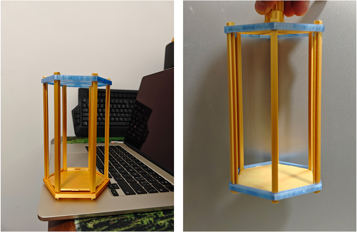
First, I tested one cover to verify that reducing the gap effectively fixed the 6 columns (left image), then reprinted the top and bottom covers to get a rotating cage with good support structure (right image)
Upper Gear Compartment Design
After reviewing some gear design materials, I initially determined the gear module for my project, so that other gears using the same module would ensure proper meshing.
Module Calculation
In gear design, the module is a key parameter of gear dimensions, defined as the ratio of the pitch (distance between teeth) to pi (π), usually measured in millimeters. The formula for calculating the module is:
Module m = d / z
Where:
- d: Pitch circle diameter of the gear (mm)
- z: Number of teeth on the gear
Addendum circle diameter: da = m × (z + 2)
I initially planned a drive gear scheme on the central axis of the revolving lantern, with the addendum circle diameter (da) set to 20mm. I planned to set the number of teeth (z) to 16.
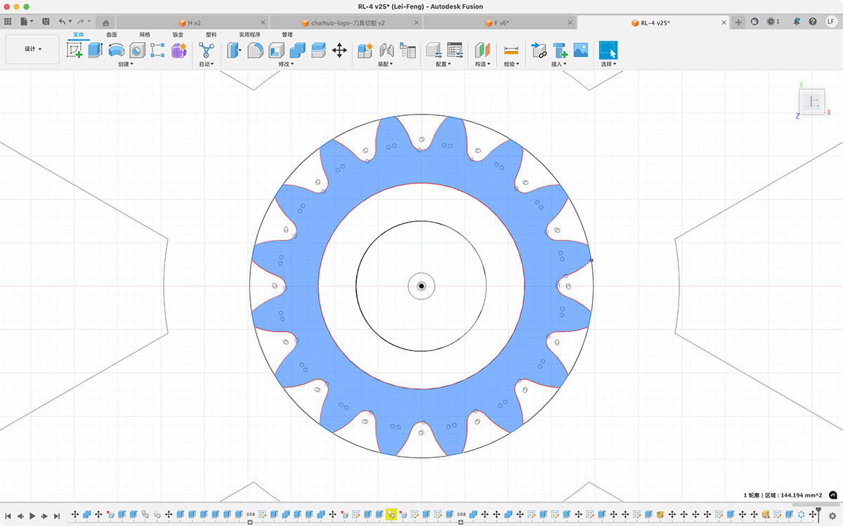
Sketch of the gear on the rotating cage's central axis
Solving for the module: Calculation yields m=20÷(16+2)≈1.11mm.
Then I installed a free Fusion gear plugin: GF Gear Generator
After installation, you can see this plugin in the utilities bar, and now you can easily create gears.
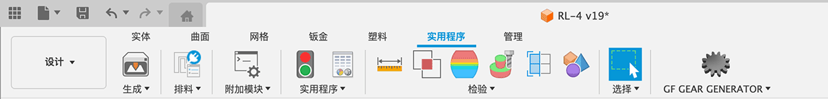
After installing the GF Gear Generator plugin, an additional icon appears in utilities
Clicking on the GF Gear Generator tool brings up a menu for designing various types of gears. I only need a Spur Gear.
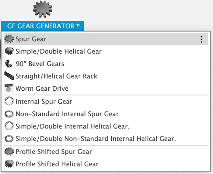
The GF Gear Generator tool lets you choose from many different gear types
In the spur gear window, I entered the module of 1.11mm that I calculated above, then entered 16 teeth, set the gear thickness to 4mm, and used the default pressure angle of 14.5 degrees. After confirmation, I got the gear structure shown in the figure.
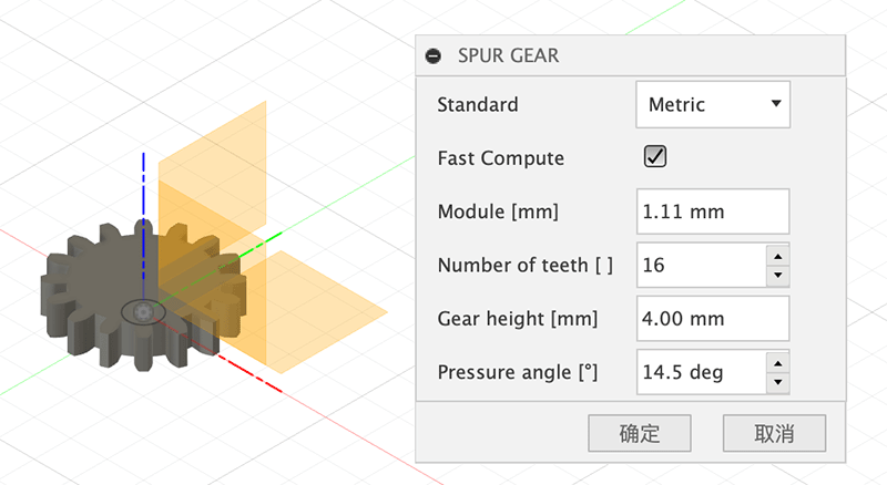
Creating a spur gear
I initially designed the gear compartment and planned to use 3D printed shafts to secure the gears, as shown below.
Initially designed gear compartment, planning to use 3D printed shafts to secure the gears
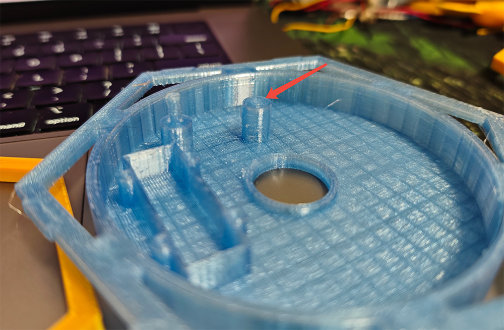
But after printing, I found that the strength of the PLC material was very limited, and even a small force could break the fragile shaft, as shown in the figure below, which would cause the entire structure to fail. So I considered using 4mm diameter steel shafts to support these drive gears, and for my project, I only needed a length of 2cm, and 2 shafts would be enough.
After looking at many options on Taobao, I found that the minimum order quantity for these small steel shafts was 100, and they were extremely inexpensive. I paid 4.22 RMB and got 100 of them. I'll leave the extra ones at Fablab for others who might need them.

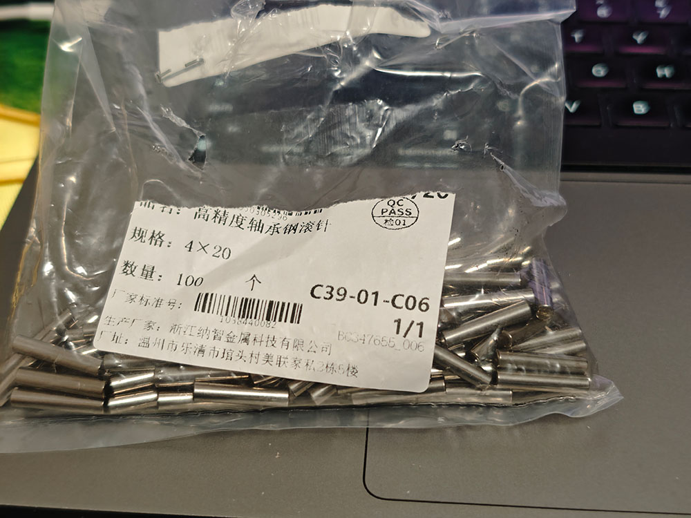
100 steel shafts with a diameter of 4mm and length of 2cm, cost only 4.22 RMB including shipping, which is a bit unbelievable
To find the appropriate hole diameter, I designed and printed 3 gears with different hole diameters: 4mm, 4.2mm, and 4.25mm. I found that:
- The 4mm steel shaft couldn't be inserted at all;
- The 4.2mm could be inserted relatively easily, but turning the gear required a bit of force, making it suitable for the shaft hole of the steel shaft base, allowing the steel shaft to be inserted into the base without being too loose;
- The 4.25mm felt just right, could be inserted very easily, and the gear could rotate smoothly, so I used this size for the shaft holes of the gears.
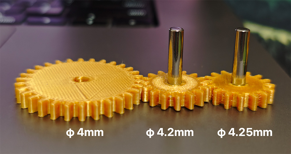
3D printed test of different gear hole diameters on the 4mm steel shaft
I tried to place several gears in appropriate positions. To be honest, I don't have much experience in this area, I just felt this arrangement should work.
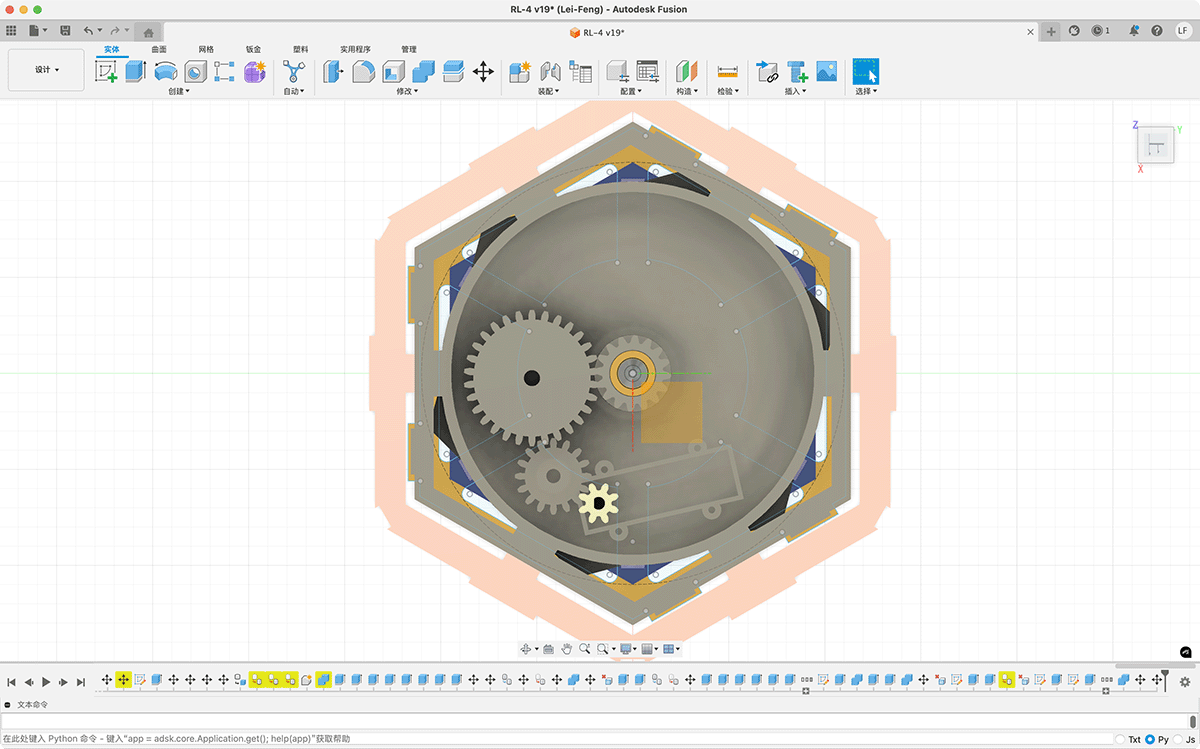
Adjusting the positions of several gears through the top view
After some trial and error, I preliminarily completed the design of the gear compartment and gear structure. The box structure of the gear compartment is for placing the motor, as shown below.
Preliminarily completed design of the gear compartment and gear structure
The effect after 3D printing the gear compartment and gears, and installing the steel shafts.
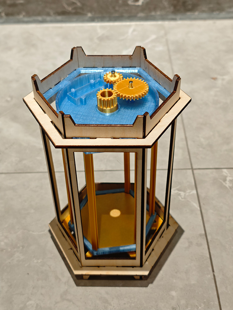
I tried rotating the lantern's rotating cage and felt the effect was good. Both the rotating cage and gears worked smoothly, as shown in the video below.
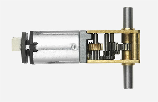
I purchased Tozbamboo train model components: https://detail.tmall.com/item.htm?from=detail&id=794818823372&skuId=5589242529650&spm=tbpc.orderdetail.suborder_itemtitle.1.5ae06aa6YUIz6Q, and found this dual-sided output shaft motor:
N20-10D dual-sided output shaft motor-130rpm, priced at approximately RMB ¥30.02
Product Parameters
| Product ID | LA009 |
|---|---|
| Input Terminal | SH1.0-2P |
| Rated Voltage | 3V |
| Working Voltage Range | 2V ~ 4V |
| Stall Torque | 350 |
| No-load Speed (RPM) | 130 |
| Motor Rotation Direction | CCW |
| Output Shaft Type | Side Dual D-type Shaft |
Next, I plan to add an electronic device layer to the gear compartment and redesign a circular PCB.