Magical Revolving Lantern System Design
Plan Adjustment Explanation
During the project progress, I recently completed the mechanical structure design of the revolving lantern's rotating shade, which prompted me to reassess and adjust the entire system. Through practical testing of the mechanical structure, I found the following limitations in the original hardware plan:
- Insufficient rotational drive: The originally planned Mini Fan cannot provide enough torque to drive the shade rotation, requiring a more powerful drive solution
- Limited lighting effects: The six onboard LEDs cannot provide omnidirectional lighting effects, affecting the visual performance of the revolving lantern
- Limited interactive experience: Single-direction gesture recognition cannot adapt to user operation from different angles
- Insufficient power supply: Fixed power cords limit the mobility and flexibility of the device
Based on these findings, I made comprehensive adjustments to the system plan, adopting solutions such as an N20 dual-shaft worm gear motor, dual RGB light strips, multi-directional gesture sensors, and a portable battery system to provide better user experience and system performance. These adjustments also required me to redesign the PCB to support the new hardware components and functions.
The core functional modules of the current project have been adjusted to:
- Shade rotation system: Using the Grove Mini Fan DC driver to drive the N20 dual-shaft worm gear motor, which rotates the lantern shade through a gear mechanism.
- RGB lighting effects: Using two 14-LED programmable full-color RGB light strips, installed back-to-back to achieve 360-degree visibility.
- Multi-directional gesture interaction: Implementing omnidirectional gesture recognition and control through three parallel APDS-9960 gesture sensors.
- Wi-Fi connection function: Implementing status synchronization between multiple lanterns and remote control via a web interface through the MQTT protocol.
- Portable power system: Integrating a 4000mAh rechargeable battery to support mobile use.
This system integration plan will detail how to integrate these modules into a complete and reliable system based on the adjusted circular PCB design.
Magical Revolving Lantern System Design Diagram
Overview of the Adjusted Magical Revolving Lantern System Architecture
The physical structure composition diagram is shown below.
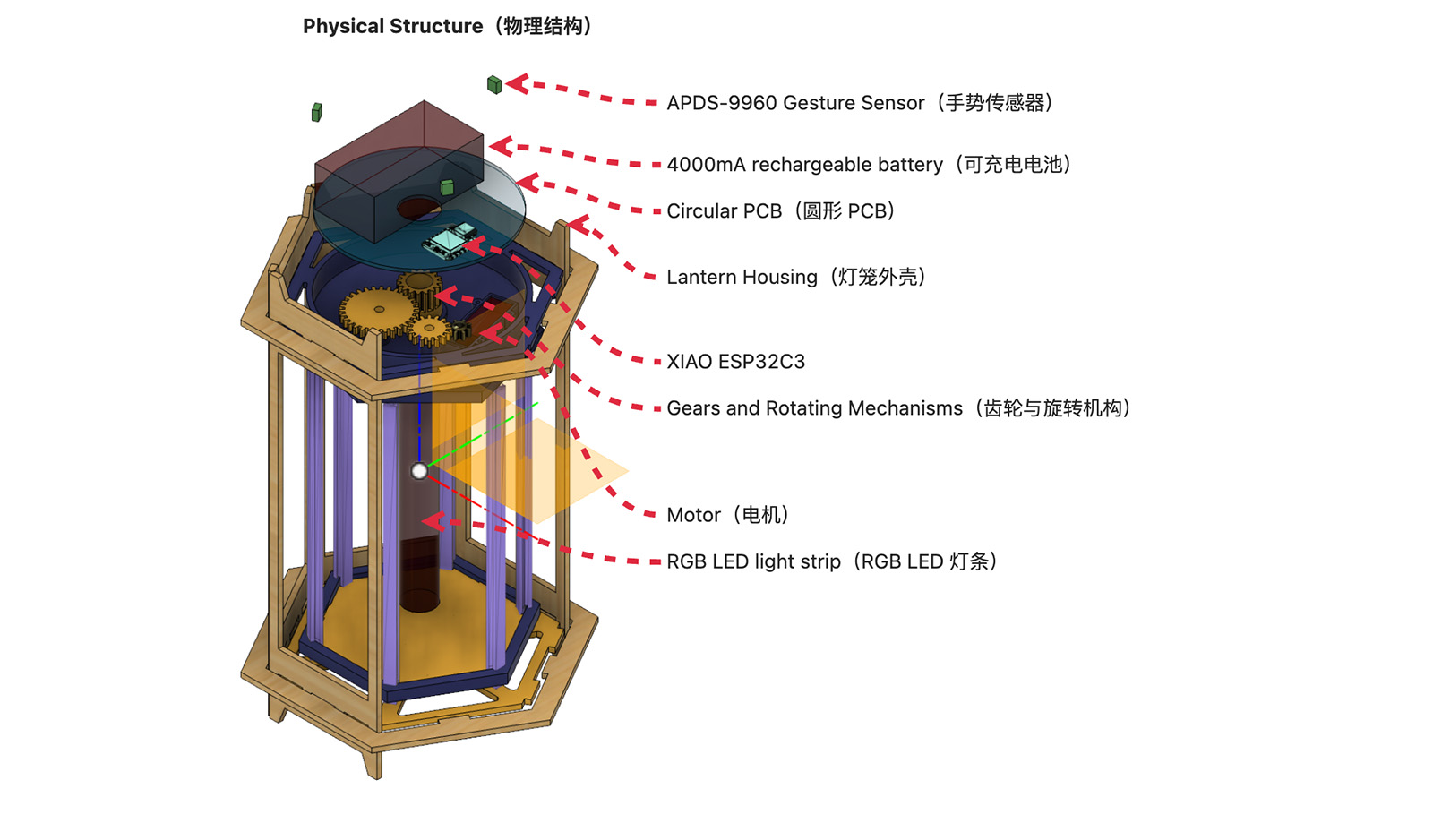
Physical structure composition diagram of the Magical Lantern
The system architecture composition of the Magical Revolving Lantern is shown in the diagram below.
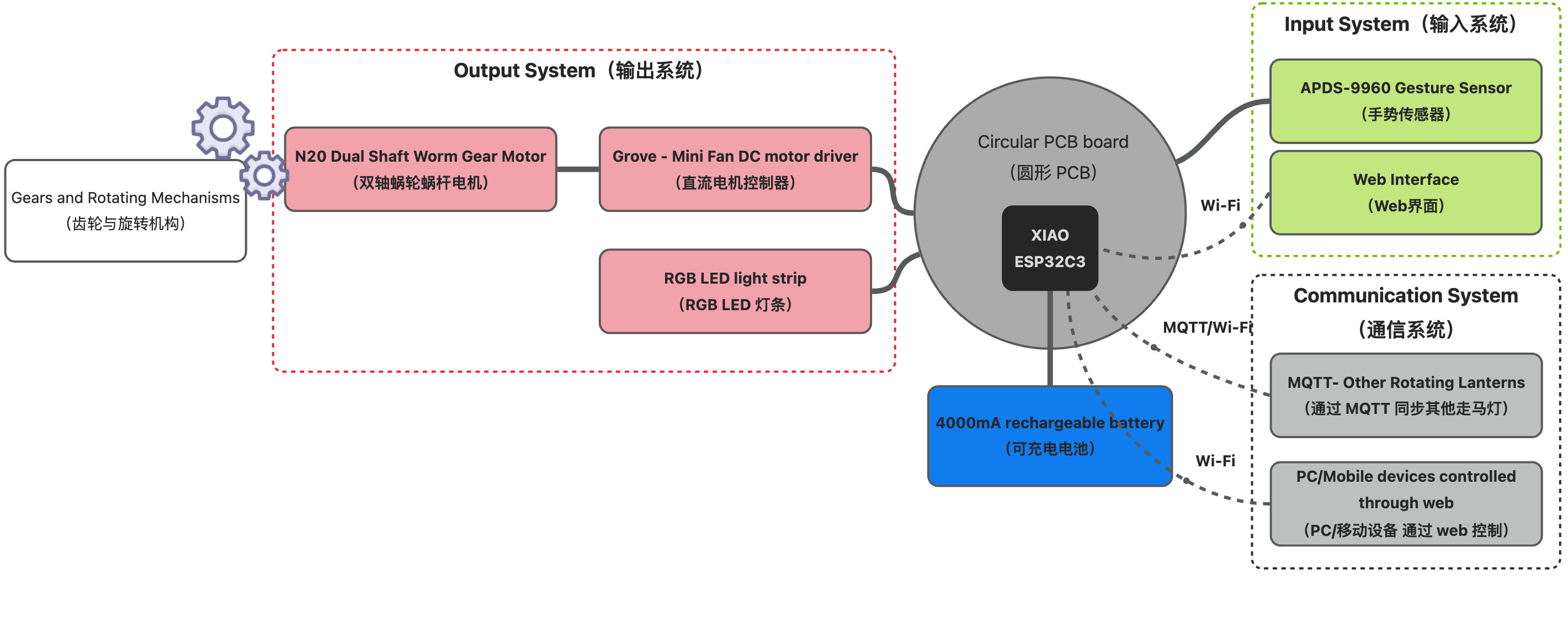
System architecture composition diagram of the Magical Revolving Lantern
Adjusted System Component List
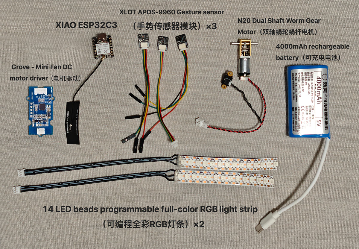
My Magical Revolving Lantern will use the following electronic hardware, with prices converted to USD from purchases made in China.
| Component Category | Component Name | Quantity | Status | Price(USD) | Notes |
|---|---|---|---|---|---|
| Control Core | XIAO ESP32C3 | 1 | Available | $5.00 | Main MCU, responsible for system control |
| Input Devices | XLOT APDS-9960 Gesture Sensor | 3 | Available | $15.00 | Three-directional gesture recognition, connected in parallel |
| Output Devices | 14 LED RGB Light Strip | 2 | Available | $4.00 | Back-to-back installation, providing 360° visual effects |
| N20 Dual-Shaft Worm Gear Motor | 1 | Available | $6.00 | Obtained from Tozbamboo 3D printing kit | |
| Grove Mini Fan Driver | 1 | Available | $8.80 | Motor control | |
| Power System | 4000mAh Rechargeable Battery | 1 | Available | $4.00 | With Type-C interface, supporting simultaneous charging and discharging |
| Structural Components | Lantern Shell | 1 | Completed | - | Completed laser-cut prototype in Week 3 |
| Rotation Mechanism | 1 | Designed Manufactured | - | 3D printed, compatible with N20 dual-shaft motor | |
| PCB & Battery Compartment | 1 | To be designed To be manufactured | - | To be done after PCB board design | |
| PCB | Circular PCB Board | 1 | To be designed and manufactured | - | Customized according to the new plan |
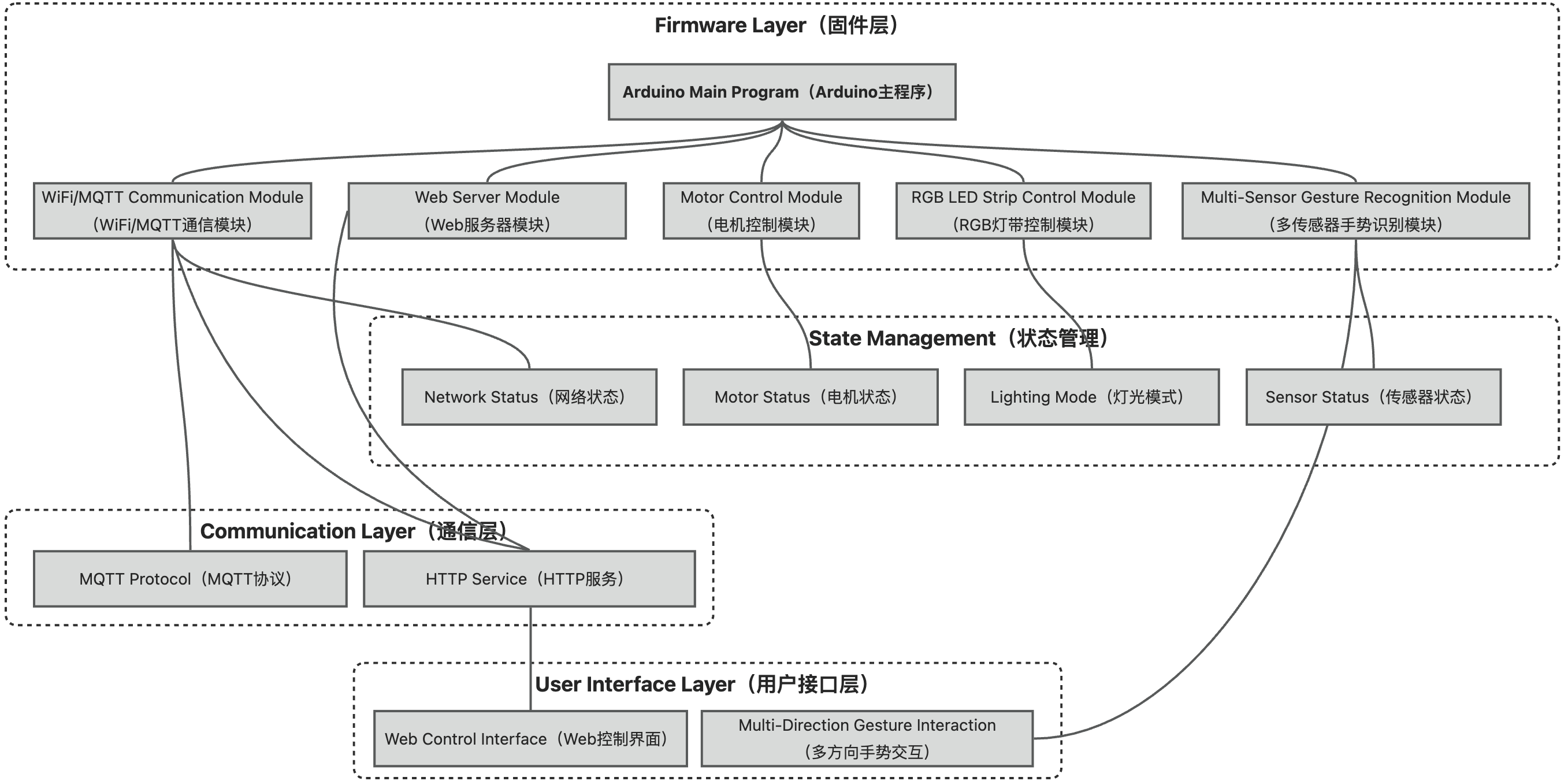
Software Architecture Diagram
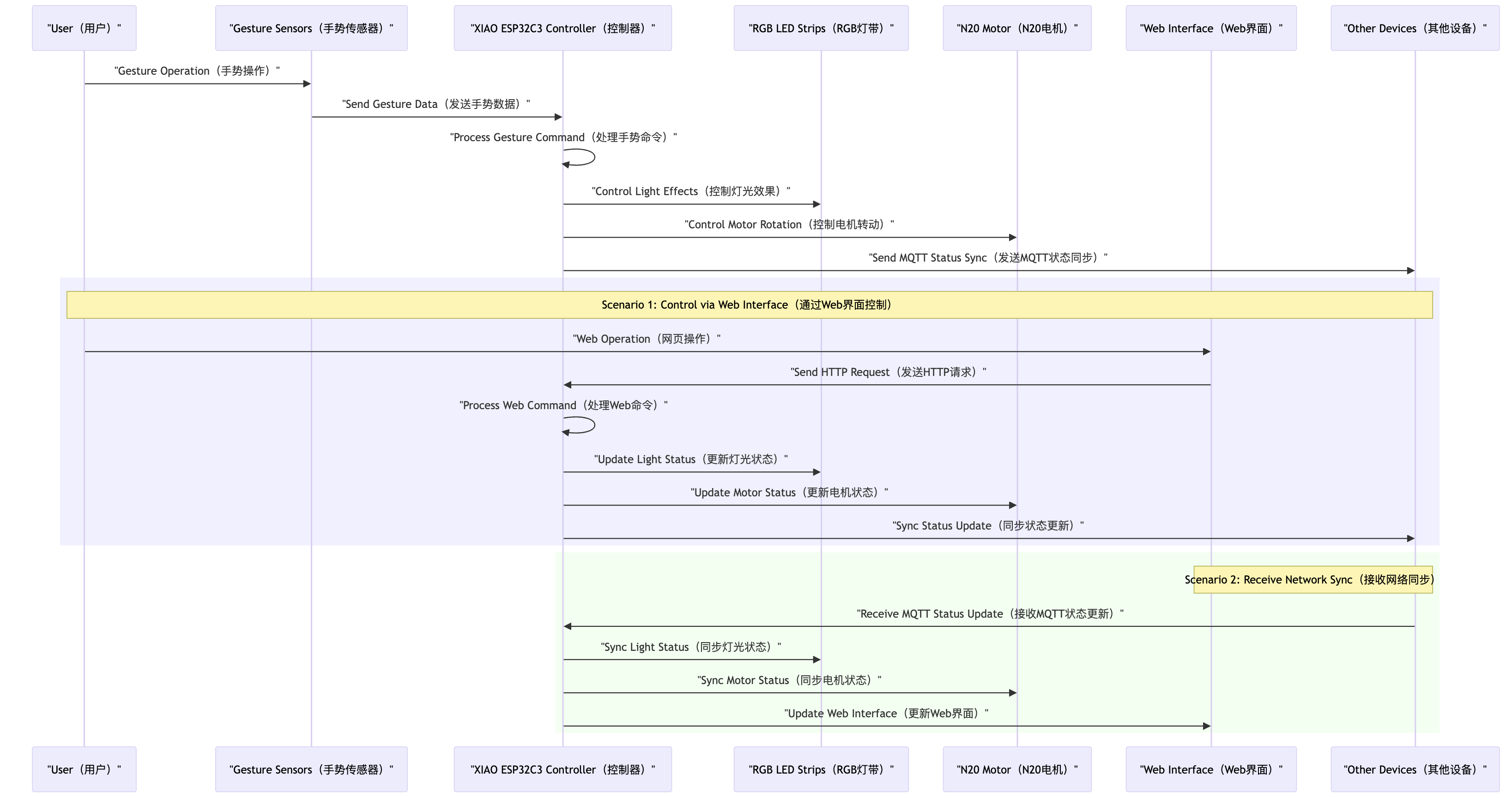
Signal Flow Diagram
Circular PCB Design Specifications and Requirements
Basic Specifications
- Shape: Circular PCB board
- Diameter: Approximately 70mm (adjusted according to the size of XIAO ESP32C3 and all interface requirements)
- Layers: Double-layer PCB (providing sufficient routing space)
- Material: FR-4 standard material
- Surface Treatment: Lead-free HASL (complying with environmental requirements)
Key Design Requirements
- Remove the 6 onboard LEDs from the original design
- Add the following functional interfaces:
- 5V power input/output interface
- 3 parallel APDS-9960 gesture sensor interfaces
- 2 programmable RGB light strip connection interfaces
- Motor driver connection interface
Interface Design Details
Power System Interface
- Battery Interface: JST 2-pin connector for connecting the 4000mAh rechargeable battery
- USB-C Interface: For external power supply or debugging
- 5V Output Interface: 2 sets of 5V and GND pins for powering external components
Gesture Sensor Interface
- I2C Interface×3: Interfaces designed for 3 parallel APDS-9960 gesture sensors
- Each interface includes: VCC(3.3V), GND, SDA(data line), SCL(clock line)
- All 3 interfaces share the same I2C bus, but each interface can independently control the VCC power
RGB Light Strip Interface
- Light Strip Interface×2: Supporting parallel connection of 2 programmable RGB light strips
- Each interface includes: 5V, GND, data control pin
- Data control pins connect to the GPIO pins of XIAO ESP32C3
Motor Control Interface
- Motor Driver Interface: Connecting the Grove Mini Fan motor driver
- Includes: VCC(5V), GND, control signal pin
- Control signal pin connects to a GPIO pin of XIAO ESP32C3
Adjusted Integration Steps
Phase One: PCB Design and Manufacturing (Estimated 5-7 days)
- Circular PCB Design
- Complete schematic design according to the new plan
- Design circular PCB layout
- PCB routing and design verification
- PCB Manufacturing and Assembly
- Produce the PCB board
- Purchase and prepare all components
- Solder the XIAO ESP32C3 and interface connectors
- Interface Testing
- Test the 5V power system
- Test the I2C bus
- Test GPIO output interfaces
Phase Two: Component Integration (Estimated 2-3 days)
- Sensor System Integration
- Connect 3 APDS-9960 gesture sensors
- Write multi-sensor management code
- Test sensor response
- RGB Light Strip Integration
- Install 2 RGB light strips
- Integrate the Adafruit_NeoPixel library
- Implement basic lighting effects
- Motor System Integration
- Install the N20 dual-shaft worm gear motor
- Connect the Grove Mini Fan driver
- Test motor control functions
- Power System Integration
- Connect the 4000mAh rechargeable battery
- Test charging and discharging functions
- Measure system power consumption
Phase Three: Software Development (Estimated 2-3 days)
- Basic Firmware Development
- Integrate multi-sensor processing code
- Implement RGB light strip control logic
- Implement motor control functions
- Communication System Implementation
- Set up WiFi connection function
- Implement MQTT communication protocol
- Develop web control interface
- Function Integration
- Implement gesture control logic
- Develop multi-lantern synchronization function
- Create battery management system
Phase Four: Mechanical Structure Integration (Estimated 5-7 days)
- Transmission Mechanism Implementation
- Use the already designed transmission device
- 3D print transmission parts
- Test transmission effect
- Lantern Shell Adaptation
- Modify lantern shell design
- Create mounting structures for PCB and battery
- Install RGB light strip brackets
- Final Assembly
- Assemble all components
- Secure connecting cables
- Perform overall balance adjustment
Adjusted Testing Plan
Unit Testing
| Test Object | Test Content | Expected Result | Passing Criteria |
|---|---|---|---|
| Multi-sensor System | Three-directional Gesture Recognition | Recognize gestures from three different directions | Recognition accuracy >85% |
| RGB Light Strip Control | Lighting Effect Control | Implement light strip marquee effect | Smooth visual effect |
| Motor Control | Speed Control and Start/Stop | Smooth motor startup and speed adjustment | Response time <150ms |
| Battery System | Battery Life | Operating time under normal use | >3 hours |
| Communication System | MQTT Message Sending/Receiving | Device message synchronization | Delay <200ms |
Integration Testing
| Test Scenario | Test Content | Expected Result | Passing Criteria |
|---|---|---|---|
| Omnidirectional Gesture Control | Gesture operations from three directions | System responds to gestures from any direction | Response rate >90% |
| Light and Motor Coordination | Control synchronized changes of light and rotation | Coordinated light and rotation effects | Good visual effect |
| Multi-lantern Synchronization | Interaction of two or more devices | Changes on one device synchronize to other devices | Synchronization delay <300ms |
| Power Performance | Full-load operation test | Stable power supply from power system | Voltage fluctuation <0.2V |
System Testing
| Test Aspect | Test Content | Expected Result | Passing Criteria |
|---|---|---|---|
| Reliability | Continuous Operation Test | System operates stably for a long time | No failures for 24 hours |
| Network Adaptability | Testing in Different Network Environments | System can adapt to network changes | Automatic reconnection success rate >95% |
| User Experience | Actual User Operation Test | Users can intuitively operate the system | High operation satisfaction |
| Power Consumption Test | Power Consumption in Different Modes | Record and optimize power consumption performance | Meets battery life requirements |
Potential Failure Analysis
| Failure Point | Risk Description | Preventive Measures | Failure Handling Plan |
|---|---|---|---|
| PCB Overload | Multiple devices in parallel may cause PCB overload | 1. Increase PCB copper thickness 2. Widen power traces 3. Monitor system temperature | 1. Software current limiting protection 2. Automatically reduce power consumption when temperature is too high |
| I2C Conflict | Multiple sensors in parallel may cause address conflicts | 1. Verify sensor addresses 2. Software detection of address conflicts 3. Use I2C multiplexer | 1. Automatically detect available sensors 2. Downgrade to single sensor mode |
| RGB Light Strip Failure | Light strip data line interference or damage | 1. Add signal buffer 2. Keep data lines short and direct 3. Shield high-speed signal lines | 1. Light strip self-check 2. Single light strip downgrade mode |
Maintenance and Lifecycle Considerations
Modular Design and Maintainability
The adjusted Magical Revolving Lantern adopts a highly modular design to ensure easy maintenance and upgrades:
- Component Independence
- PCB design uses connector connections instead of directly soldering external components
- Three gesture sensors can be individually replaced and adjusted
- RGB light strips use standard interfaces for easy replacement or upgrade
- Maintenance Convenience
- Lantern shell design features a removable base for easy access to internal components
- Battery is designed to be removable, supporting quick replacement
- All interfaces and connectors are clearly labeled
- Fault Diagnosis Support
- Built-in self-diagnosis program to check the status of each module via the web interface
- LED indicators provide system status and error codes