Week 2: 3D Modeling the Magic Lantern
Quick Start with FreeCAD
3D modeling with CAD was relatively unfamiliar to me, as I had only previously used SketchUp to create some architectural interior space sketches. Neil emphasized the importance of mastering parametric design and recommended that I download and install FreeCAD.
To be honest, learning FreeCAD was a somewhat challenging process for me. The documentation is relatively limited, and the key to using this software lies in understanding its operational methods. I found a CAD modeling workbook, as shown below, containing over 100 CAD drawings. Due to time constraints, I attempted to complete the first three exercises.
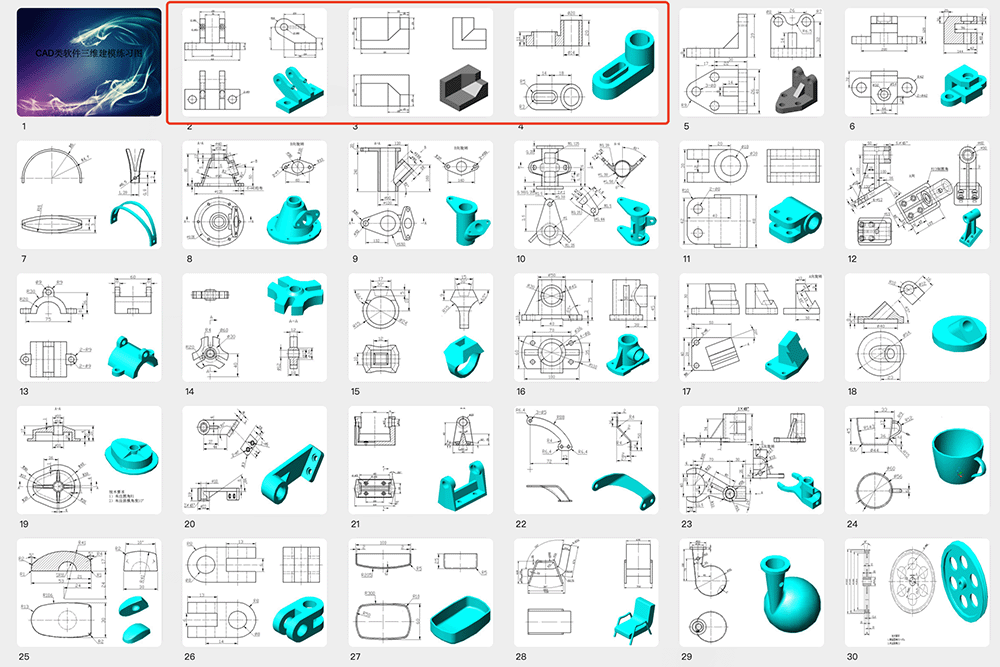
CAD model workbook used for practice
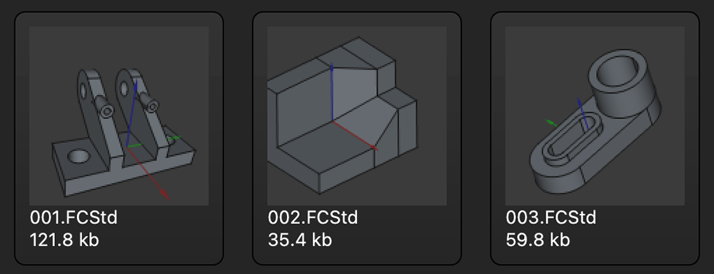
The first three models completed in FreeCAD
After completing these three exercises, I developed a basic understanding of FreeCAD's functionality. Here are the fundamental points.
Workbench Switching
As a beginner, I primarily switched between these two workbenches:
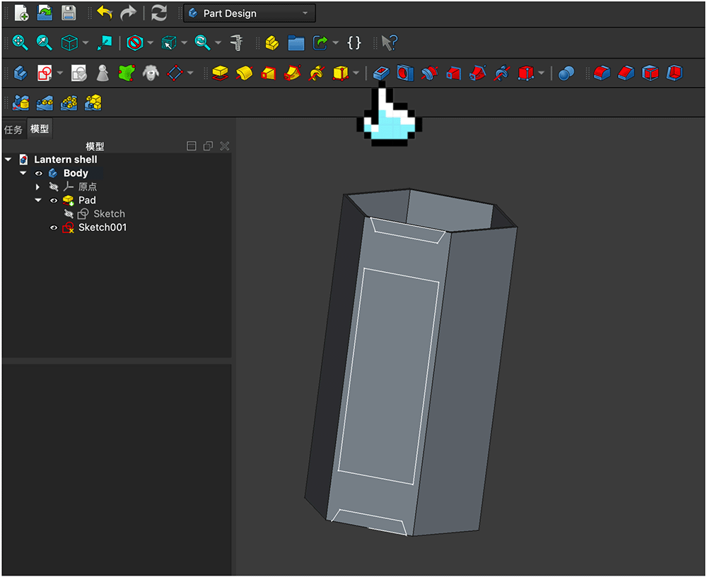
 Part Design: Mainly used for creating solid models. The image below shows the Part Design workbench during my model practice.
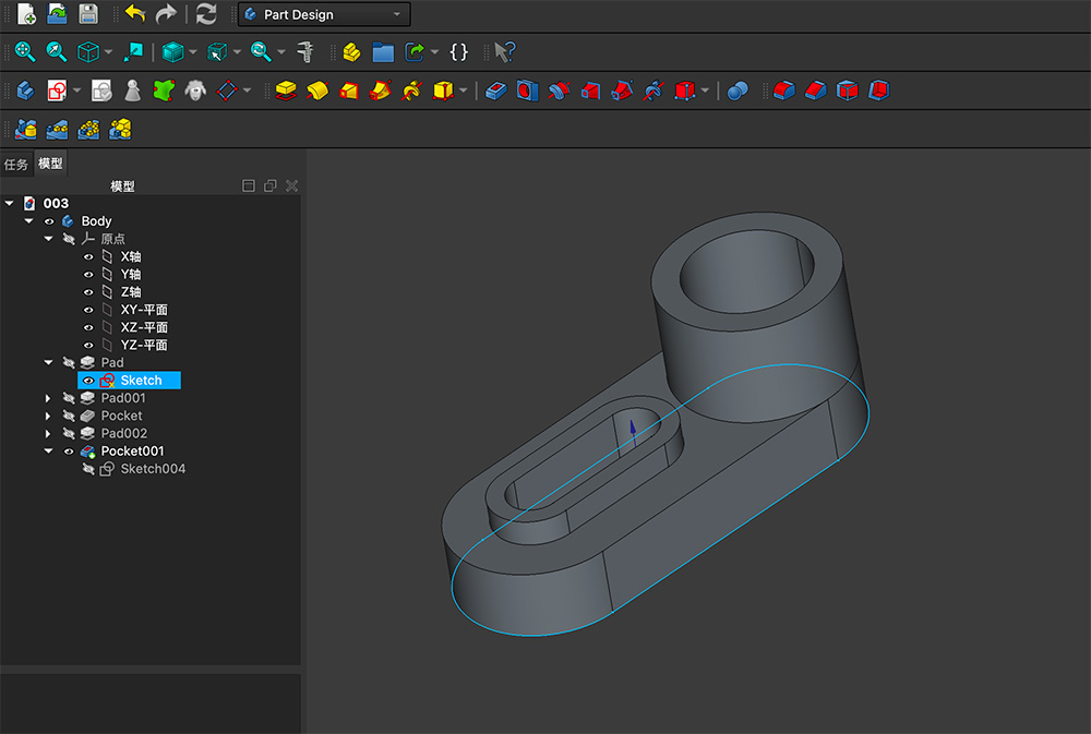
Part Design workbench
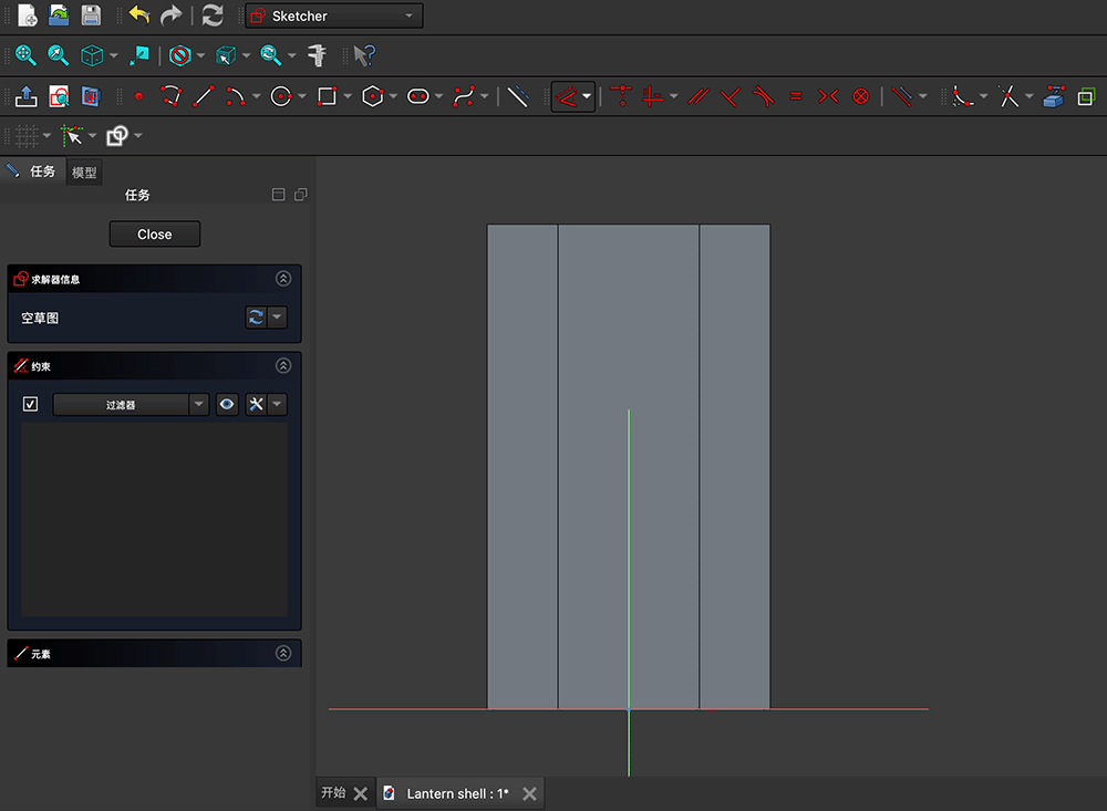
 Sketcher: Used for creating 2D sketches, which form the foundation of 3D modeling. The image below shows
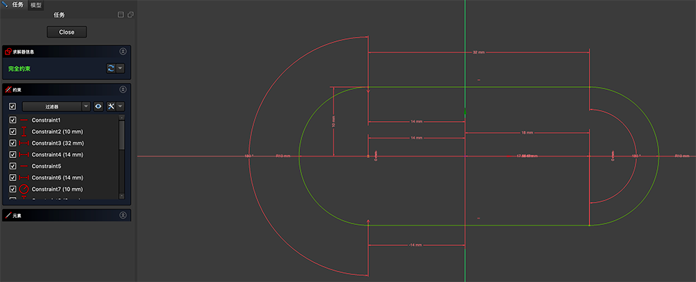
Sketcher workbench, with all points and lines in a fully constrained state
Basic Workflow
- Create new Body
- Select axis plane to add Sketch
- Draw 2D profile
- Add Constraints
- Create 3D form through Pad, Pocket, or Revolution operations
Common Constraint Types
- Geometric constraints: Vertical, horizontal, parallel, perpendicular, etc.
- Dimensional constraints: Distance, angle, radius, etc.
- Relative constraints: Coincident, tangent, symmetric, etc.
Parametric Design Features
- Use constraints rather than fixed dimensions
- Quickly modify models by changing parameters
- Maintain clarity of design intent
Modeling the Magic Lantern's External Frame
During the Spring Festival, I visited the Nanyue Temple in Hengyang, Hunan Province, China. I noticed that the street lamps in the temple were designed in the style of traditional Chinese lanterns, as shown below. I thought this design would be perfect for the external frame of my Magic Lantern and decided to model it based on this example.

Below is the modeling process for the lantern's external frame.
Creating a New Body
Open FreeCAD and create a new file, click the ![]() icon to add a new
icon to add a new Body, save the file and name it Lantern shell. The interface should now look like this:
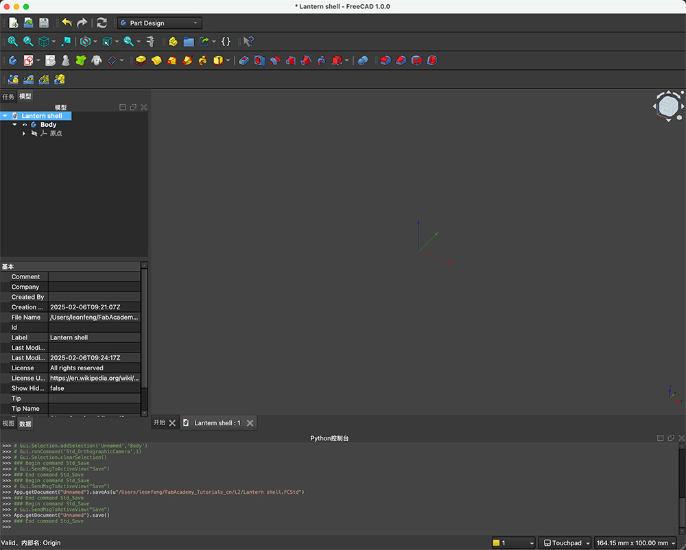
Creating a new body and saving the file
Drawing the Basic Hexagonal Profile
The lantern has a hexagonal prismatic shape overall. Click the ![]() Create sketch icon, and you'll be prompted to select an attachment. Here, select the XY-plane (reference plane), as shown below.
Create sketch icon, and you'll be prompted to select an attachment. Here, select the XY-plane (reference plane), as shown below.
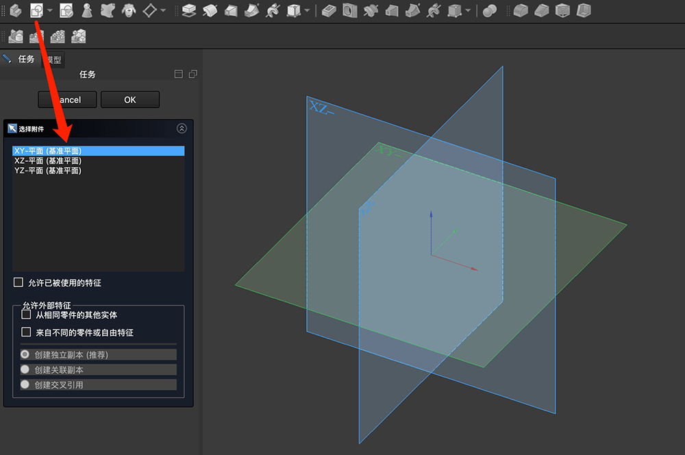
When creating a sketch, you need to select a reference plane. For this project, we select the XY-plane
After entering sketch mode, the top menu bar changes to show point, line, and constraint tools. We select the hexagon tool, as shown below.
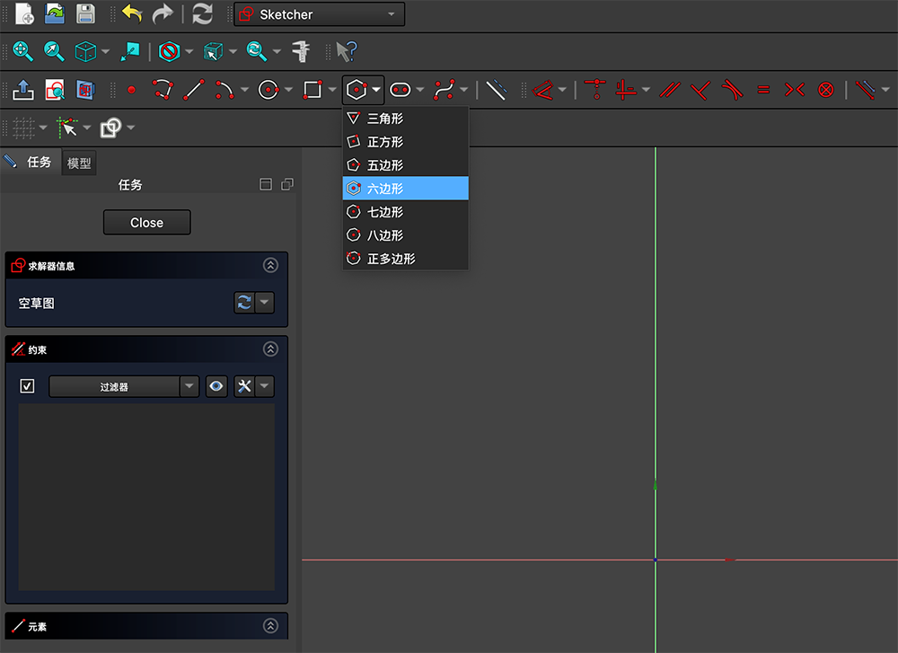
Selecting the hexagon tool
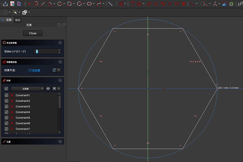
With the hexagon tool selected, click at the coordinate center to establish the hexagon's center point, then drag outward to create a hexagon. I positioned two points of the hexagon on the horizontal x-axis. Click again to fix the hexagon's size. At this point, you can see in the "Constraints" panel that many constraints have been automatically added to ensure it's a regular hexagon. The solver information shows insufficient constraints: 1 degree of freedom, as shown below. At this stage, if you drag the corner points of the hexagon, you can still change its size and angle.
Adding Dimensional Constraints
Press the esc key or right-click to exit the hexagon tool. As shown below, add horizontal distance constraints in steps 1-4.
- First click point 1 that lies on the x-axis - the selected point will turn green (though it might be subtle).
- Then click the origin point.
- Open the top dimension menu and select the "Horizontal Distance" constraint command.
- In the "Enter length" dialog that appears, enter 70mm.
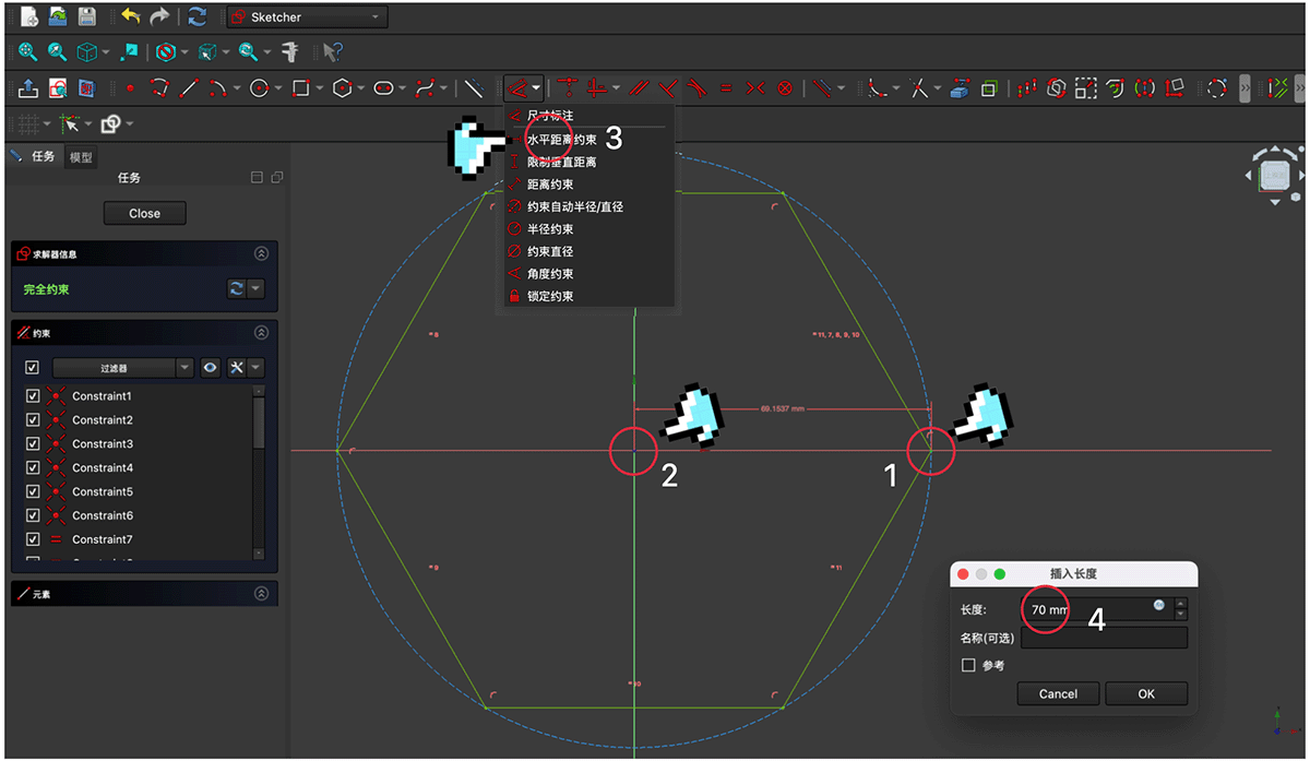
Setting a horizontal distance constraint for one point of the hexagon requires 4 steps
After clicking OK to confirm, as shown below, a red 70mm dimension line will appear between the hexagon point and the origin. Additionally, the hexagon changes from white to green, and the solver information on the left shows green text indicating: Fully constrained.
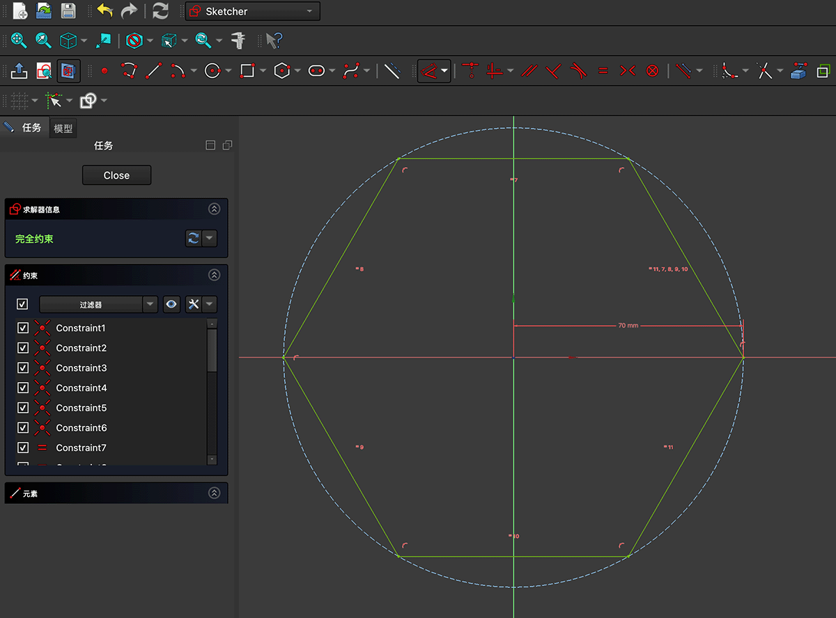
Successfully adding constraints to achieve a "Fully constrained" state for the hexagon
Using the same method, draw the inner wall hexagon line and add a horizontal constraint of 67mm (I didn't use Offset geometry here because it would require manually constraining all 6 points of the new hexagon). Now we have two fully constrained nested hexagons, as shown below.
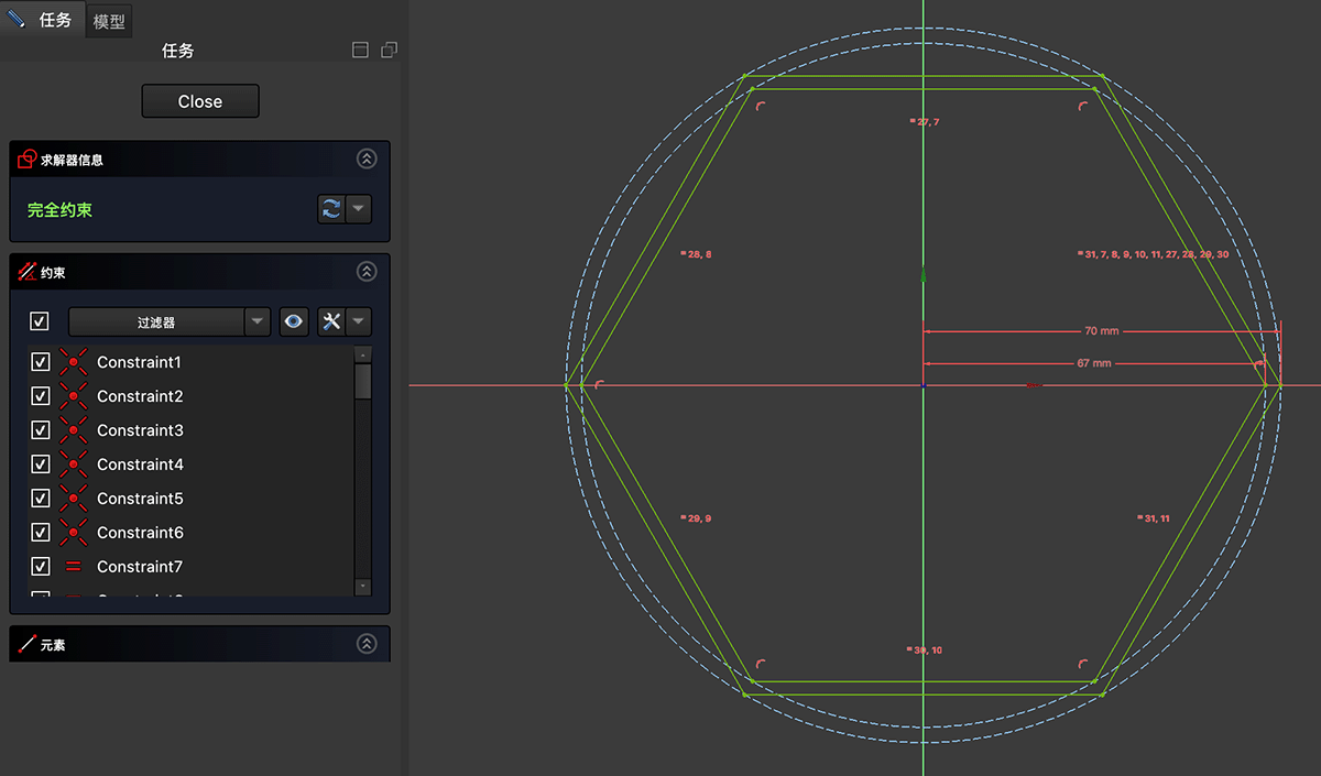
Two nested hexagons representing the inner and outer walls of the lantern
Creating the 3D Form
Click the "Close" button in the task panel while in sketch mode shown above to return to Part Design mode. As shown below, keeping the sketch selected, click the  "Pad" (Pad) function indicated by the finger.
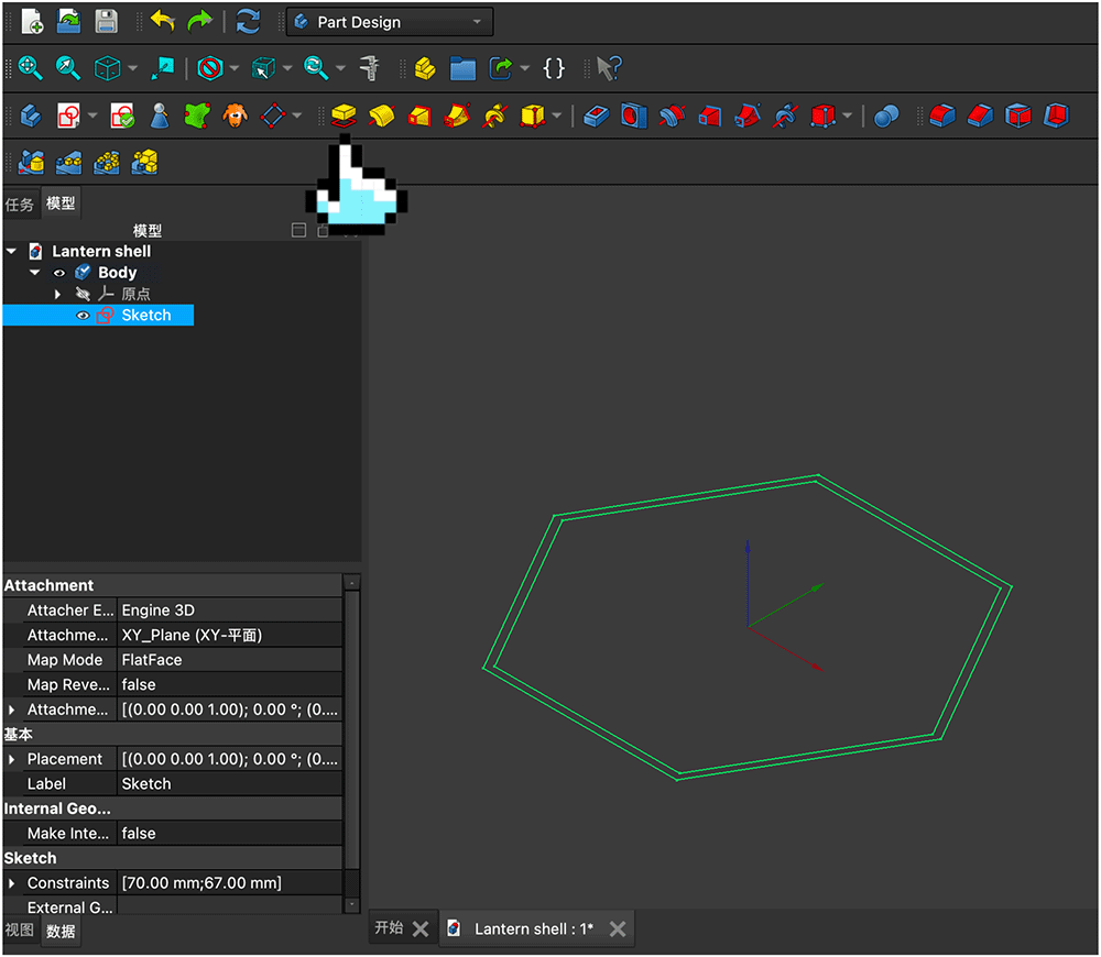
In Part Design mode, select the sketch and use the Pad function
In the Pad parameters panel, set the length to 240mm, as shown below. We now have a hollow hexagonal prism. Click the "OK" button in the task panel to confirm the settings.
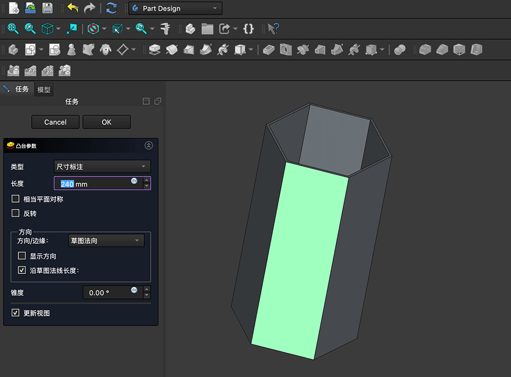
Pad parameter settings
The model resource list now shows a Pad above the Sketch, as shown below. We can double-click Pad to reopen the pad panel and adjust the length.
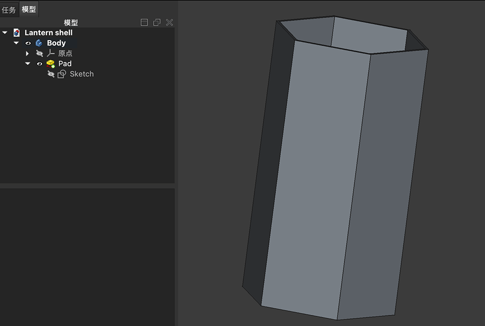
The model resource list now includes the Pad content
Adding Openwork Patterns to the Sides
Next, we need to create openwork patterns on all 6 sides. I made a simple plan for the openwork area on one face, as shown below, where the black parts represent the areas to be cut out.
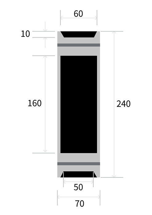
Planning the areas to be cut out, with dimensions marked
Now we need to create a new sketch on the prism's face. As shown below, select one outer face to highlight it (1), then click the sketch button (2).
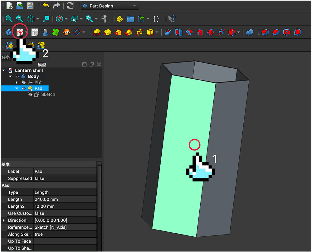
Select one face of the hexagonal prism then click the sketch button
Now we can draw the sketch on the selected face, as shown below.
Entering sketch mode for one outer face of the hexagonal prism
Following the planned openwork dimensions above, draw the shapes and add appropriate constraints, as shown below.
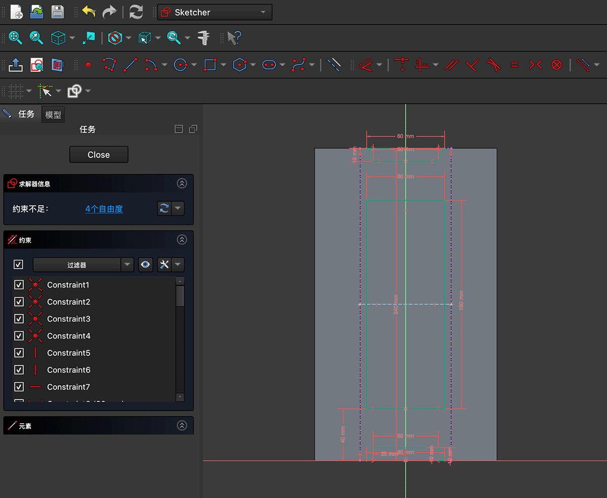
Drawing the openwork area and adding appropriate constraints
Click the "Close" button in the task panel to return to Part Design mode, then click the  "Pocket" (Pocket) function shown below.
Selecting the Pocket function in Part Design mode
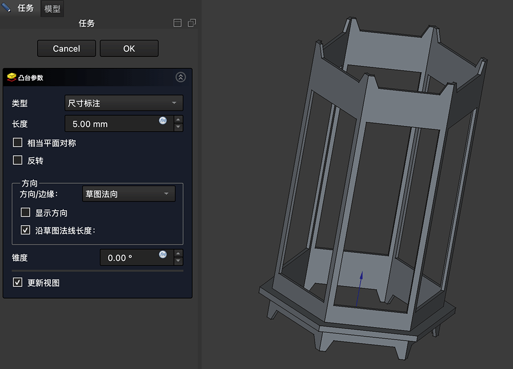
In the pocket parameters panel, set a value greater than the hexagonal shell thickness (5mm in this case), and you'll see the openwork effect as shown below.
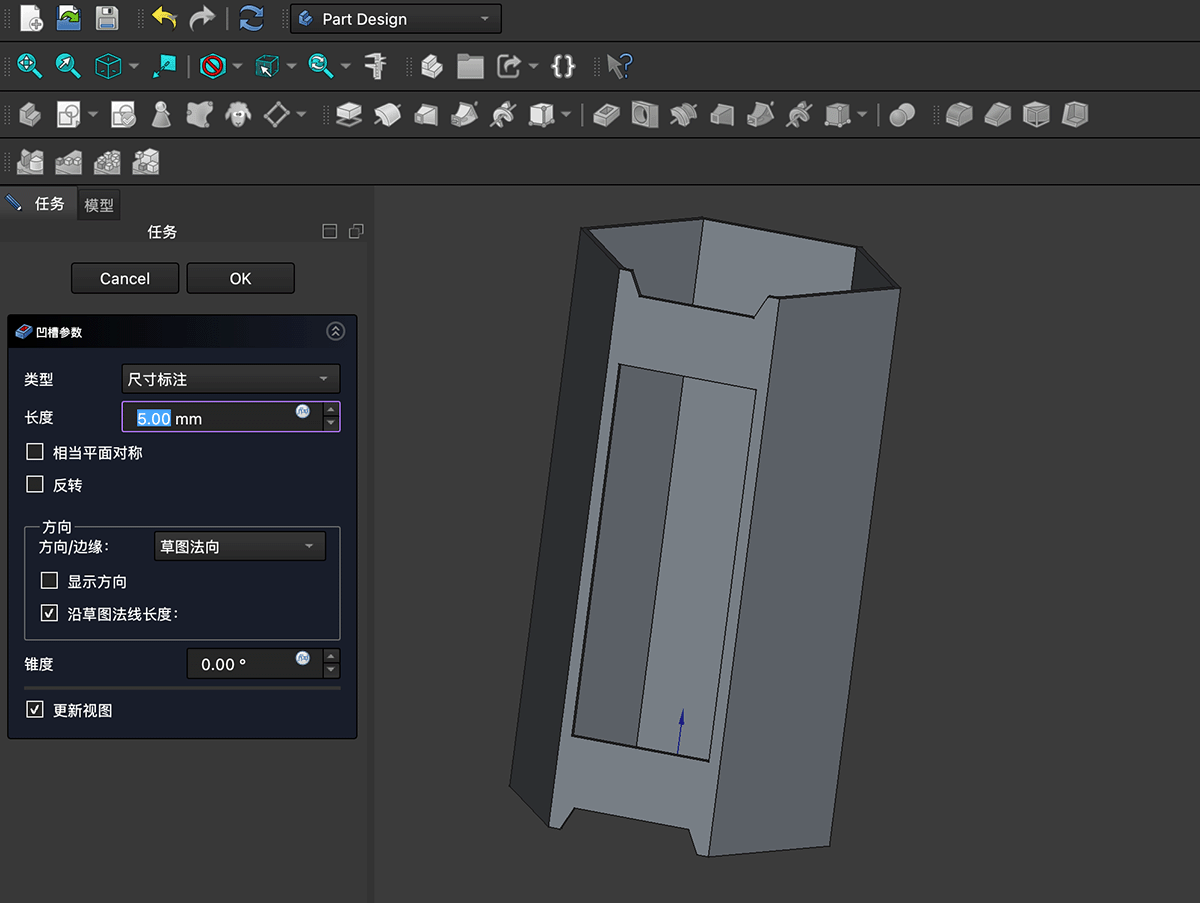
Setting the pocket depth value in the parameters panel
After clicking OK to confirm and returning to Part Design mode, you can see the Pocket content added to the model resource list, as shown below.
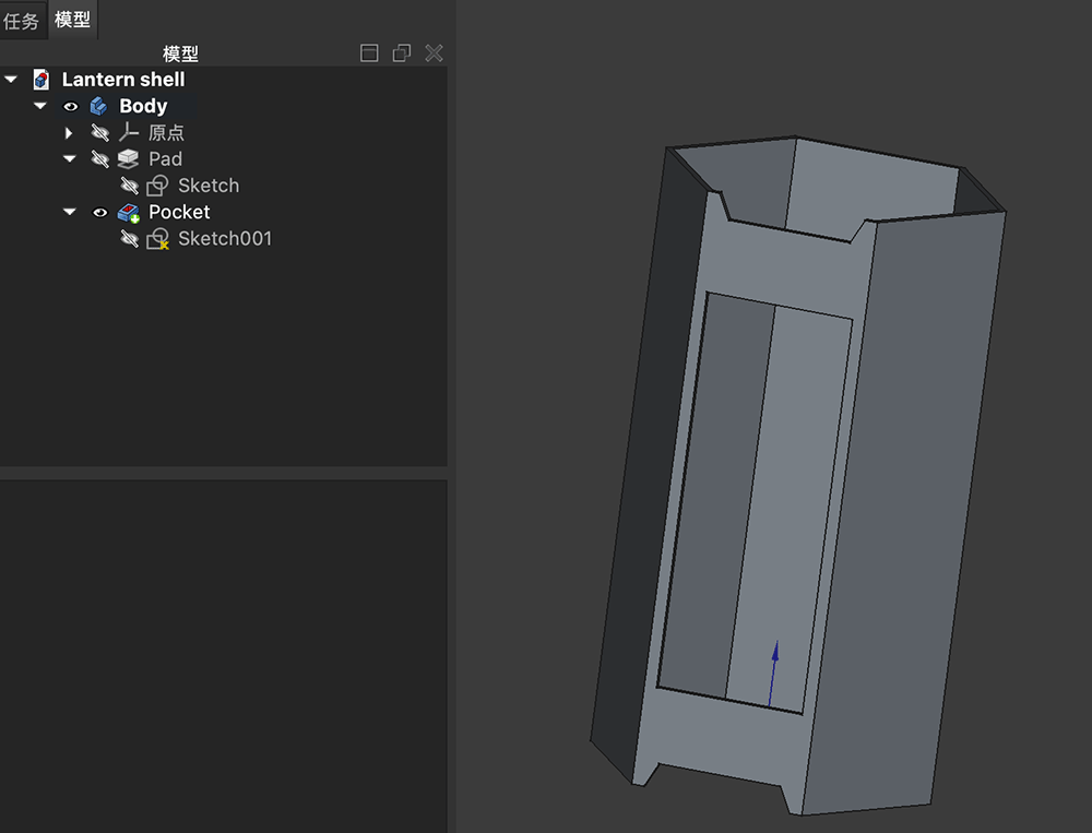
The Pocket content has been added to the model resource list
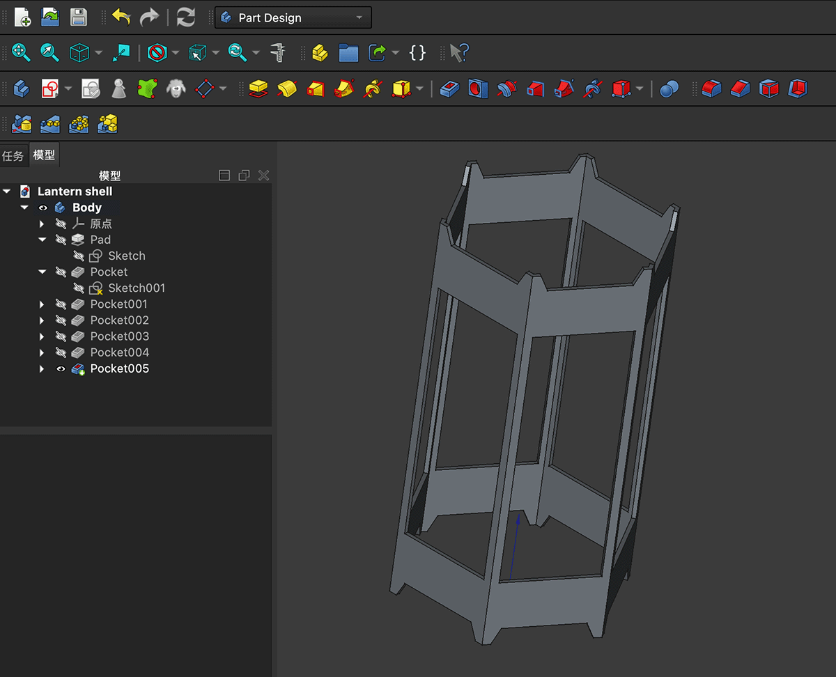
You can return to Sketch001 under Pocket, copy all sketch content, and replicate the same sketch for the other 5 faces, then use the Pocket function to achieve the openwork effect shown below.
Adding Top and Bottom Hoops
First, enter Sketch001 and copy all content of the two nested hexagons. Then create a new sketch under Body in the model resource manager, again selecting the xy-axis, paste the sketch, and modify the inner hexagon's constraint length to 80mm, as shown below.
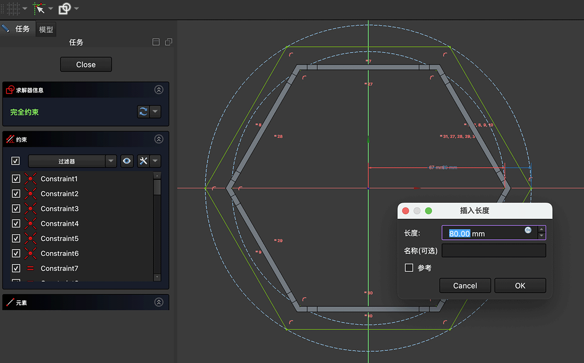
Paste the nested hexagons in the newly created sketch and modify the inner hexagon's constraint length to 80mm
Set the z-axis position of Sketch007 to 20mm, raising the sketch plane to the position shown below.
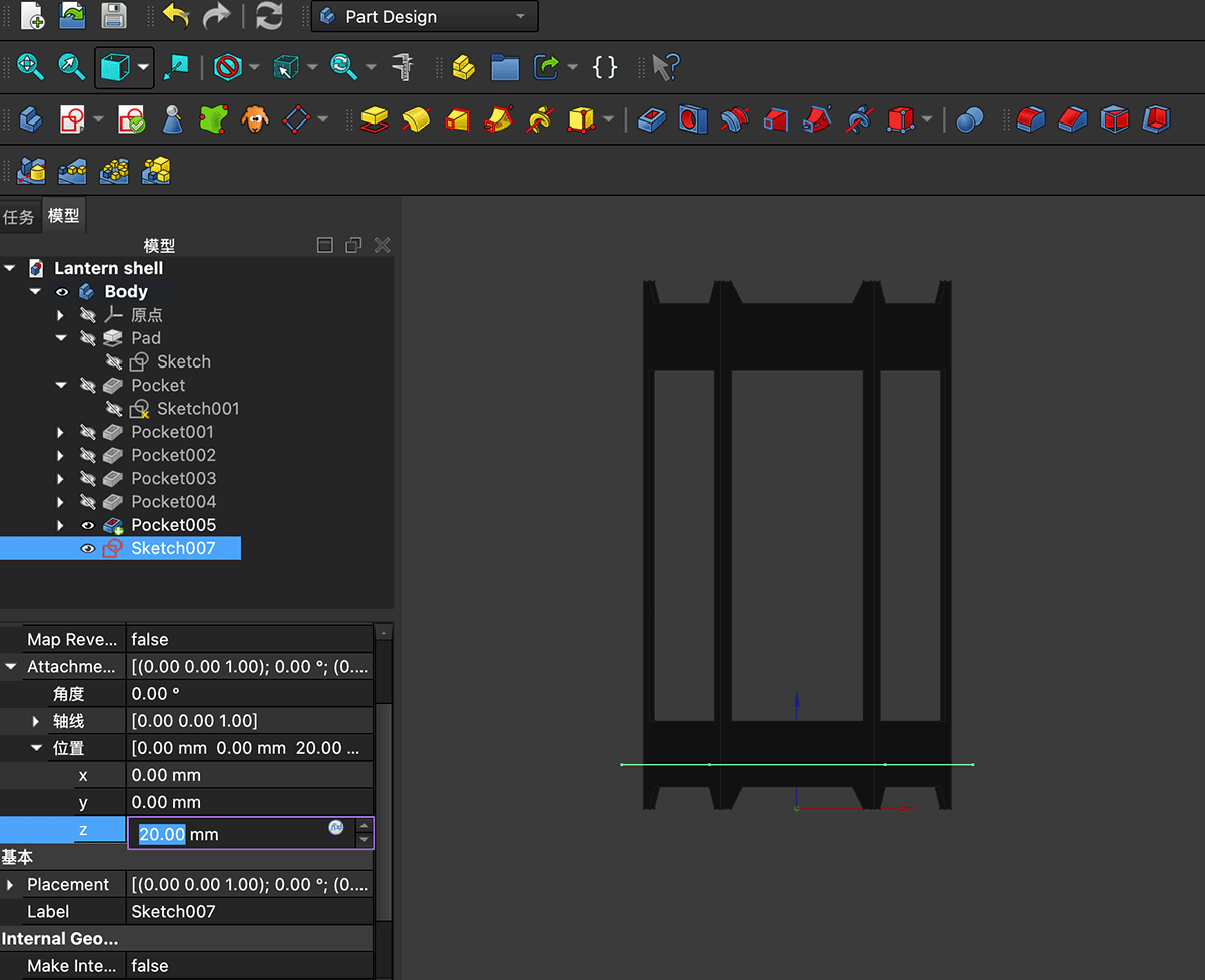
Modifying the z-axis position of the newly created Sketch007
Use the Pad tool with a length of 5mm to create the bottom hoop, as shown below.
Creating the bottom hoop using the Pad tool
Use the same method to create the top hoop at 215mm, completing the initial modeling work for the Magic Lantern's external frame. Save the file.
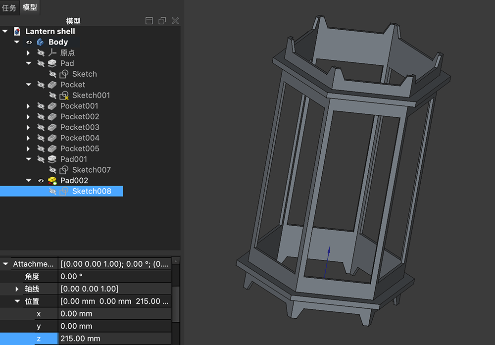
Adding the top hoop at z-axis 215mm using the same method
Download FreeCAD Source File
Modeling for Laser Cutting
The model from the above exercise is a solid piece, but considering that we need to use a laser cutter to create this shell, the design approach needs to be modified. Although FreeCAD is free, many of its operations are not user-friendly for beginners. So I tried several different CAD software options.
First, I tried Shapr3D. This is the most comfortable CAD software I've ever used. The interaction is very user-friendly, and after completing the built-in tutorials, I quickly created my lantern shell model, as shown below. However, I discovered that exporting 2D sketches requires the Pro version, so I decided to try other options.
Lantern shell structure made in Shapr3D, adapted for cutting plans
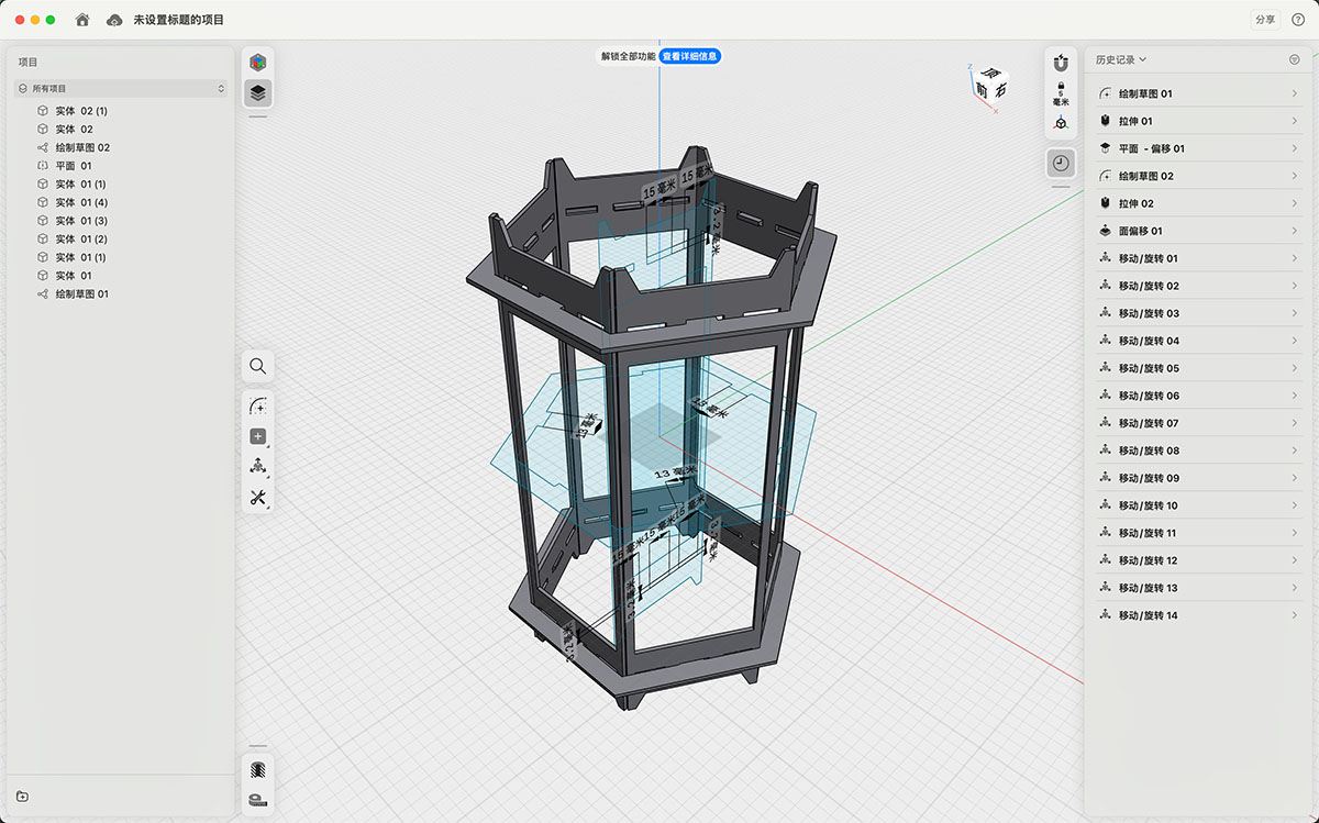
Fab Academy provides students with Autodesk Fusion trial accounts, so I switched to Fusion. Given my previous familiarity with the parametric design process, this transition was also very quick. I used two sketches to build the lantern's vertical structure and horizontal hoop structure respectively. I added 3x15mm holes at the top and bottom of each vertical unit for fixing the horizontal hoops and making space for the middle equipment. After completing the structural design, I used Fusion's sketch right-click menu "Export DXF" function to export DXF files of both the vertical structure and horizontal hoop structure sketches.
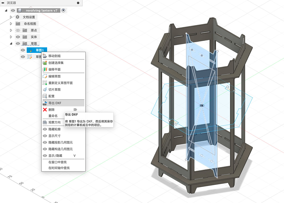
Lantern shell structure made in Autodesk Fusion, adapted for cutting plans. Fusion can directly export sketches as DXF
In Adobe Illustrator, I combined the two DXF files into one and replicated the components in the required quantities in preparation for laser cutting.
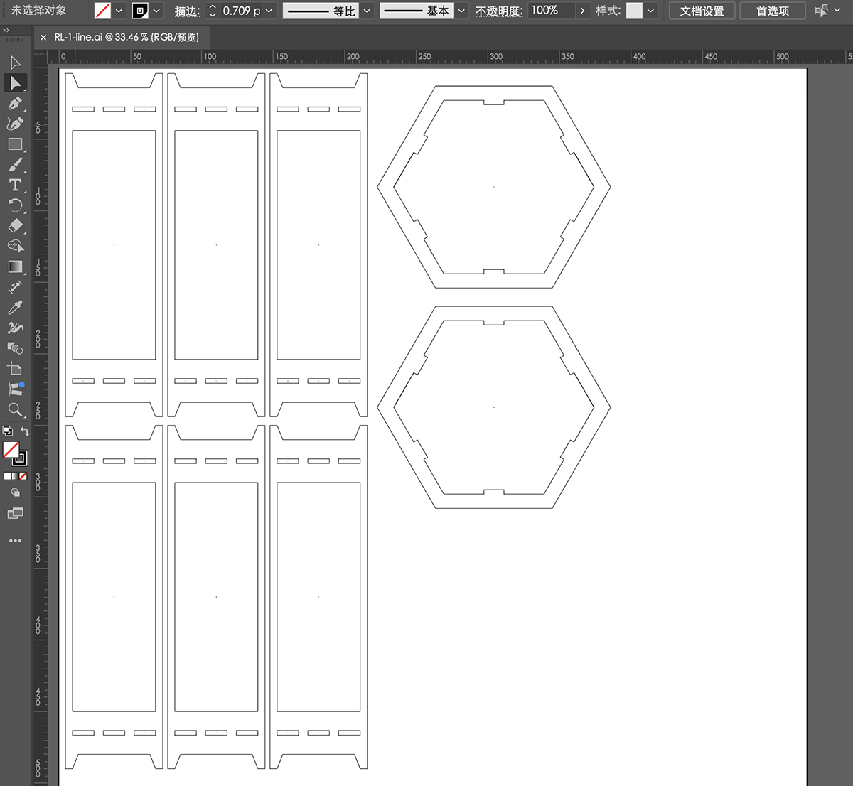
Editing the required DXF files for laser cutting in Adobe Illustrator