Week 11: Individual Assignment - Dual-Node Gesture-Controlled Smart Network System
The main task of this week's group assignment is to design and implement a distributed communication network system, exploring information exchange and collaboration between multiple nodes. By building a wired or wireless network structure, the goal is to achieve data transmission and synchronized control between nodes, thereby deepening the understanding of networking principles and real-world applications. Team members are required to work together to complete the system design, node construction, and network protocol implementation, ultimately enabling information sharing and linkage among multiple nodes.
See this week's group assignments: https://fabacademy.org/2025/labs/chaihuo/docs/week11/chaihuo/week11_group_assignment/
1. Project Introduction
The main goal of this week's individual project is to design, build, and connect wired or wireless nodes with network or bus addresses, and implement control of local input/output devices. Based on my previous gesture sensor controlling fan and LED project and final project concept, I decided to create a dual-node smart network system that implements gesture control synchronization between two devices (in my final project, multiple smart lanterns will synchronize actions wirelessly, so gestures performed on any lantern will cause all lanterns to respond).
Specific project objectives include:
- Building two identical nodes, each containing a XIAO ESP32C3 expansion board and an APDS-9960 gesture sensor
- Implementing wireless communication between nodes, allowing them to send and receive control commands
- Designing a communication protocol to ensure that gestures detected on either node can synchronously control LEDs on both nodes
- Creating an intuitive user feedback mechanism to display network connection status and control synchronization
2. Materials and Equipment
Hardware Components
- 2 XIAO ESP32C3 development boards (self-made)
- 2 APDS-9960 gesture sensor modules
- Connecting wires/jumper wires
- USB data cables (2)
- Power adapters (5V/2A, 2)
In Week 8, I had 5 XIAO expansion board PCBs manufactured through JLCPCB. Previous courses only used 1 board, and for this course, I soldered components onto another board. The second time soldering this PCB felt much easier, lighting up on the first try.
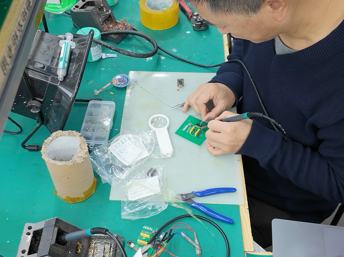
Soldering components for the second PCB was much smoother, lighting up on the first try
To easily distinguish between them, I installed 5 red LEDs on the newly soldered board (previously I used blue LEDs).
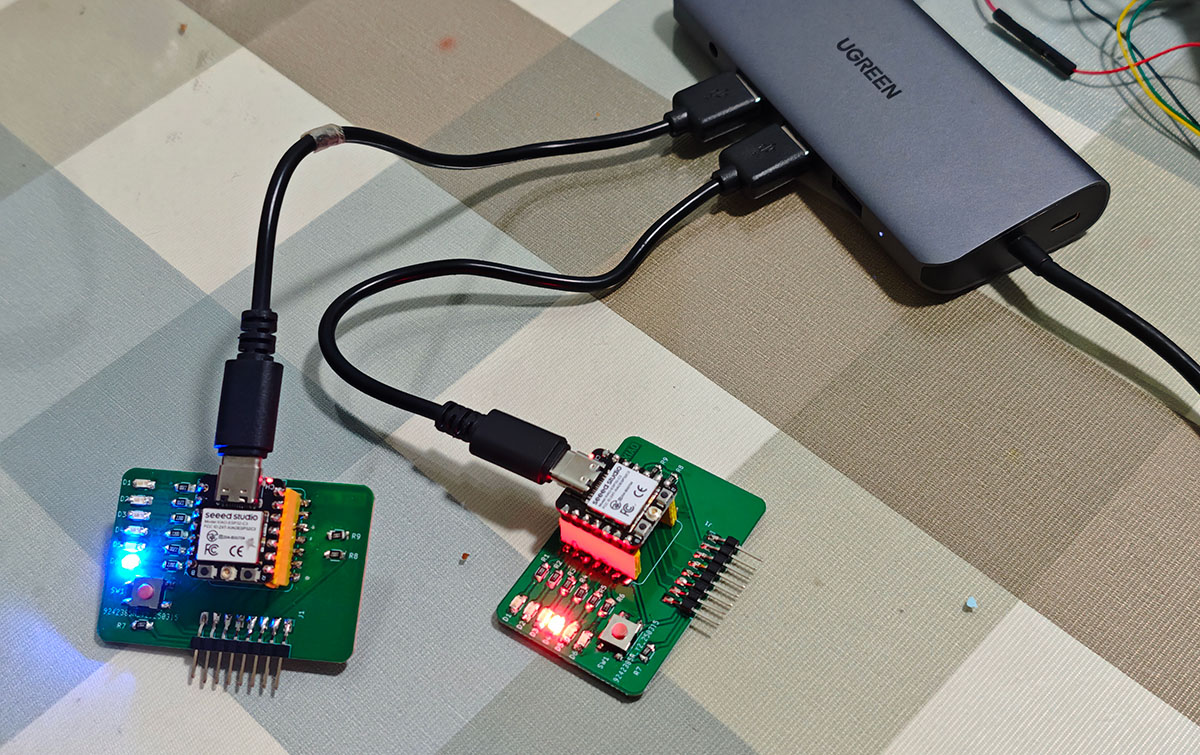
For easy differentiation, I used red LEDs on the newly soldered PCB
Additionally, remember to install the antenna for the XIAO ESP32C3, as we'll need its Wi-Fi functionality for the work below.
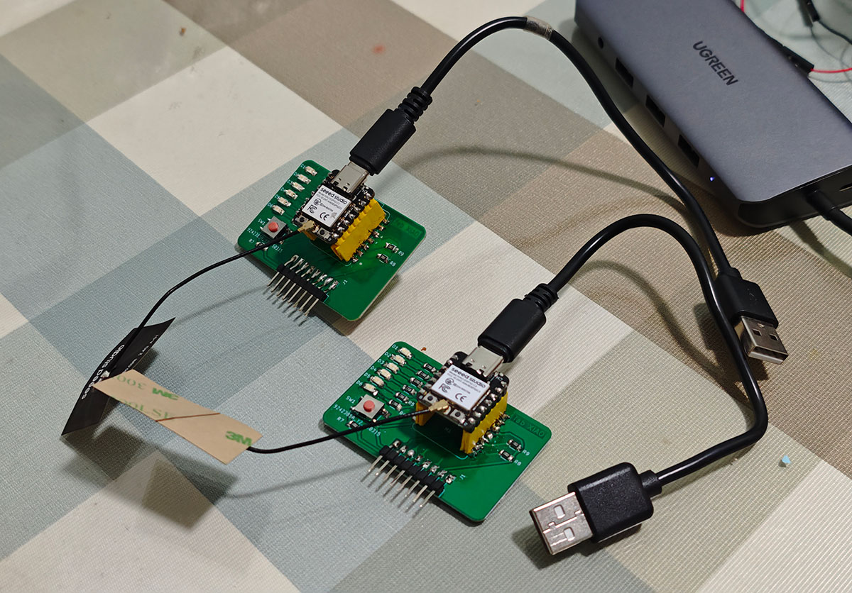
Remember to install the antenna for the XIAO ESP32C3
When installing the antenna, apply a bit of pressure downward until the antenna is firmly seated in the base.
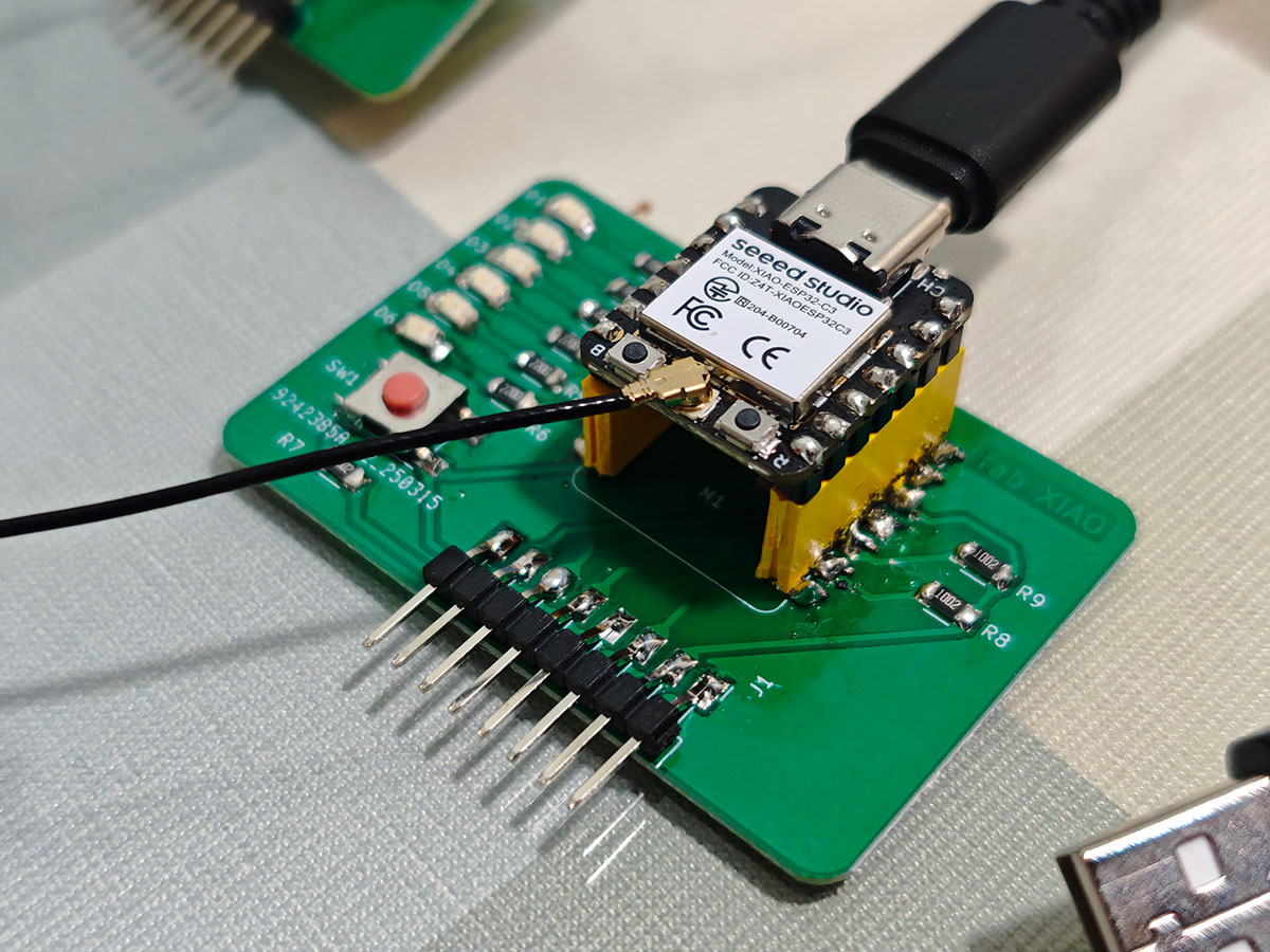
Apply some pressure downward until the antenna is firmly seated in the base
Software Tools
- Arduino IDE
- XLOT_APDS9960AD library (for gesture sensor)
- WiFiManager library (for Wi-Fi connection management)
- ArduinoJson library (for structured message processing)
- ESPAsyncUDP library (for UDP communication)
3. System Design
3.1 Network Architecture Design
This project uses a peer-to-peer wireless network architecture, with both nodes connecting to the same Wi-Fi network and communicating directly through the UDP protocol. The reasons for choosing UDP over TCP are:
- Low Latency: UDP has no connection establishment process, resulting in lower transmission delays, suitable for real-time control scenarios
- Simple and Efficient: No need to maintain connection state, low protocol overhead, suitable for simple command transmission
- Broadcast Capability: UDP supports broadcasting, convenient for future expansion to multi-node systems
The system's network topology is shown in the diagram below:
[Node 1]                    [Node 2]
┌─────────────┐            ┌─────────────┐
│ ESP32C3     │            │ ESP32C3     │
│ Gesture     │◄──Wi-Fi───►│ Gesture     │
│ Sensor      │   (UDP)    │ Sensor      │
│ LEDs        │            │ LEDs        │
└─────────────┘ └─────────────┘3.2 Communication Protocol Design
Defining a simple but reliable JSON format message protocol:
{
  "sender": "NODE_ID",      // Sending node identifier
  "cmd": "COMMAND_TYPE",    // Command type
  "data": {                 // Command data
    "gesture": 0,           // Gesture type
    "ledCount": 0           // LED count
  },
  "timestamp": 0            // Timestamp (milliseconds)
}Main command types:
HELLO: Node discovery and state synchronizationGESTURE: Gesture control commandSTATUS: Status update notification
3.3 Node Identification and Address Assignment
Each node needs a unique identifier. I use a simple method to generate node IDs:
- Generate a unique identifier based on the ESP32C3's chip ID
- Use the first 8 bits of the identifier as the node name
- Use a fixed UDP port (e.g., 8266) to receive messages
- Broadcast messages to the network (
255.255.255.255) or to known peer IP addresses
After startup, nodes execute a "discovery" process:
- Connect to the Wi-Fi network
- Broadcast HELLO messages
- Establish communication connection after receiving replies from other nodes
3.4 Circuit Connection Design
Since each node's hardware connection is the same as in Week 10's assignment, I will follow the previously verified connection scheme:
APDS-9960 Gesture Sensor Connection
| APDS-9960 Pin | Connection to Expansion Board Pin | XIAO ESP32C3 Pin | Function |
|---|---|---|---|
| VCC (red wire) | J1-2 (3.3V) | 3.3V | Power positive |
| GND (black wire) | J1-1 (GND) | GND | Power ground |
| SDA (yellow wire) | J1-3 (RX/D7) | GPIO20 | I2C data line (software implementation) |
| SCL (green wire) | J1-4 (TX/D6) | GPIO21 | I2C clock line (software implementation) |
LED Connection
The development board already has 6 LEDs (D0-D5), directly connected to the corresponding GPIO pins of the XIAO ESP32C3 through on-board circuits.
The wiring diagram is shown below. The expected functionality is that operating any gesture sensor will synchronously control the LED lights on both devices (increase or decrease the number of lit LEDs with up/down gestures, or turn all LEDs on/off with left/right gestures).
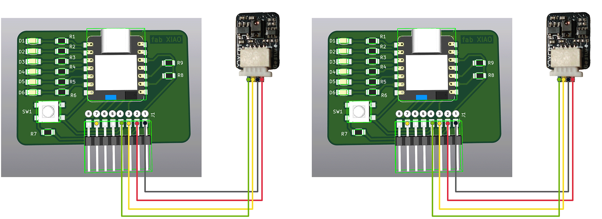
The wiring method for both sets of devices is identical
4. Program Design
4.1 Program Structure Design
The program is mainly divided into the following modules:
- Initialization Module: Wi-Fi connection, sensor setup, UDP communication establishment
- Gesture Processing Module: Detecting and parsing gesture commands
- Communication Module: Sending and receiving network messages
- Command Execution Module: Controlling local LEDs
- State Management Module: Maintaining and synchronizing node states
4.2 Core Code Implementation
For this part of the program, I used Claude 3.7 to assist with writing, with prompts roughly as follows. I also provided the complete Markdown document from Week 10's individual assignment and the Week 11 course outline link (to help the AI understand the course and assignment requirements) as background reference material.
For Week 11, my individual assignment idea is to prepare another expansion board with the same functionality, paired with the same gesture sensor, to implement dual-device synchronization via wireless network. This means that gesture commands (up/down as in Week 10, left/right controlling all LEDs on/off) received by the sensor on either device can synchronously drive the LEDs on both devices. Please help me write the program for Week 11's individual assignment based on this concept.
#include <WiFi.h>
#include <WiFiUdp.h>
#include <Wire.h>
#include <ArduinoJson.h>
#include "XLOT_APDS9960AD.h"

// WiFi settings
const char* ssid = "YourWiFiName";
const char* password = "YourWiFiPassword";

// Network communication settings
WiFiUDP udp;
const int UDP_PORT = 8266;
IPAddress broadcastIP(255, 255, 255, 255);
char packetBuffer[255];

// Pin redefinition - adapted for custom expansion board
#define SDA_PIN 20      // RX/D7 (GPIO20)
#define SCL_PIN 21      // TX/D6 (GPIO21)

// LED pin definitions
const int LED_PINS[] = {D5, D4, D3, D2, D1, D0};
const int LED_COUNT = 6;

// Gesture sensor
XLOT_APDS9960AD apds;

// Control variables
int ledCount = 0;              // Number of lit LEDs (0-6)
unsigned long lastGestureTime = 0;  // Last gesture timestamp
const int gestureDelay = 500;  // Gesture recognition interval (milliseconds)

// Node identification
String nodeId;
bool otherNodeConnected = false;
IPAddress otherNodeIP;

// Time control variables
unsigned long lastHelloTime = 0;
unsigned long lastHeartbeat = 0;

// Initialize node identifier, ensure uniqueness
void initNodeId() {
  uint64_t chipId = ESP.getEfuseMac(); // Get MAC address as unique ID
  char nodeIdBuffer[20];
  snprintf(nodeIdBuffer, sizeof(nodeIdBuffer), "Node%llX", chipId);
  nodeId = String(nodeIdBuffer);
  Serial.print("Node ID: ");
  Serial.println(nodeId);
}

// Connect to WiFi
void connectToWiFi() {
  Serial.println("Connecting to WiFi...");
  WiFi.begin(ssid, password);

  int retries = 0;
  while (WiFi.status() != WL_CONNECTED && retries < 20) {
    delay(500);
    Serial.print(".");
    retries++;
  }

  if (WiFi.status() == WL_CONNECTED) {
    Serial.println("\nWiFi connection successful!");
    Serial.print("IP address: ");
    Serial.println(WiFi.localIP());

    // Initialize UDP
    udp.begin(UDP_PORT);
    Serial.print("Listening on UDP port: ");
    Serial.println(UDP_PORT);

    // Send broadcast message to notify other nodes
    sendHelloMessage(false);
  } else {
    Serial.println("\nWiFi connection failed!");
    // Blink LED to indicate connection failure
    for (int i = 0; i < 10; i++) {
      digitalWrite(LED_PINS[0], HIGH);
      delay(100);
      digitalWrite(LED_PINS[0], LOW);
      delay(100);
    }
  }
}

// Send broadcast message
void sendHelloMessage(bool isReply) {
  unsigned long now = millis();
  // Limit HELLO message frequency
  if (!isReply && (now - lastHelloTime < 5000)) {
    return;
  }
  lastHelloTime = now;

  DynamicJsonDocument doc(256);
  doc["sender"] = nodeId;
  doc["cmd"] = "HELLO";
  doc["isReply"] = isReply;
  doc["data"]["ledCount"] = ledCount;
  doc["timestamp"] = now;

  String jsonString;
  serializeJson(doc, jsonString);

  IPAddress targetIP = isReply ? otherNodeIP : broadcastIP;
  udp.beginPacket(targetIP, UDP_PORT);
  udp.print(jsonString);
  udp.endPacket();

  Serial.print("Sending ");
  Serial.print(isReply ? "reply" : "broadcast");
  Serial.println(" message: " + jsonString);
}

// Send gesture control message
void sendGestureCommand(uint8_t gesture) {
  if (!otherNodeConnected) {
    Serial.println("No other nodes discovered, using broadcast");
  }

  DynamicJsonDocument doc(256);
  doc["sender"] = nodeId;
  doc["cmd"] = "GESTURE";
  doc["data"]["gesture"] = gesture;
  doc["data"]["ledCount"] = ledCount;
  doc["timestamp"] = millis();

  String jsonString;
  serializeJson(doc, jsonString);

  IPAddress targetIP = otherNodeConnected ? otherNodeIP : broadcastIP;

  udp.beginPacket(targetIP, UDP_PORT);
  udp.print(jsonString);
  udp.endPacket();

  Serial.println("Sending gesture command: " + jsonString);
}

// Process received message
void processReceivedMessage(String message) {
  DynamicJsonDocument doc(256);
  DeserializationError error = deserializeJson(doc, message);

  if (error) {
    Serial.print("JSON parsing failed: ");
    Serial.println(error.c_str());
    return;
  }

  String sender = doc["sender"];
  if (sender == nodeId) {
    // Ignore messages sent by self
    return;
  }

  String cmd = doc["cmd"];
  Serial.print("Received command: ");
  Serial.print(cmd);
  Serial.print(" from: ");
  Serial.println(sender);

  if (cmd == "HELLO") {
    // Check if already connected to this node, avoid duplicate processing
    bool isReply = doc.containsKey("isReply") && doc["isReply"].as<bool>();

    if (!otherNodeConnected || otherNodeIP != udp.remoteIP()) {
      otherNodeConnected = true;
      otherNodeIP = udp.remoteIP();

      // If this is not a reply message, send a reply
      if (!isReply) {
        sendHelloMessage(true);  // Send HELLO message with reply flag
      }

      Serial.print("Established connection with node ");
      Serial.print(sender);
      Serial.println();

      // Blink LEDs to indicate successful connection (once)
      bool originalLedStates[LED_COUNT];
      for(int i = 0; i < LED_COUNT; i++) {
        originalLedStates[i] = (i < ledCount); // Save current LED state
        digitalWrite(LED_PINS[i], HIGH);
        delay(100);
      }
      delay(300);
      for(int i = 0; i < LED_COUNT; i++) {
        digitalWrite(LED_PINS[i], originalLedStates[i] ? HIGH : LOW); // Restore original state
        delay(50);
      }
    }

    // Synchronize with peer state (regardless of whether it's a reply message)
    if (doc["data"].containsKey("ledCount")) {
      int remoteLedCount = doc["data"]["ledCount"];
      if (ledCount != remoteLedCount) {
        ledCount = remoteLedCount;
        updateLEDs();
        Serial.print("Synchronized LED count: ");
        Serial.println(ledCount);
      }
    }

  } else if (cmd == "GESTURE") {
    // Process gesture command
    uint8_t gesture = doc["data"]["gesture"];
    processGesture(gesture, false);

    // Synchronize other states
    if (doc["data"].containsKey("ledCount")) {
      int remoteLedCount = doc["data"]["ledCount"];
      if (ledCount != remoteLedCount) {
        ledCount = remoteLedCount;
        updateLEDs();
      }
    }
  }
}

// Check for incoming messages
void checkForMessages() {
  int packetSize = udp.parsePacket();
  if (packetSize) {
    // Receive message
    int len = udp.read(packetBuffer, 255);
    if (len > 0) {
      packetBuffer[len] = 0;
    }

    String message = String(packetBuffer);
    processReceivedMessage(message);
  }
}

// Update LED display
void updateLEDs() {
  for(int i = 0; i < LED_COUNT; i++) {
    // If i is less than ledCount, turn on the LED, otherwise turn it off
    digitalWrite(LED_PINS[i], (i < ledCount) ? HIGH : LOW);
  }
}

// Process gesture
void processGesture(uint8_t gesture, bool sendCommand) {
  switch(gesture) {
    case APDS9960_RIGHT:
      // Right swipe - Turn on all LEDs
      if(ledCount < LED_COUNT) {
        ledCount = LED_COUNT;
        updateLEDs();
        Serial.println("All LEDs turned on");
      }
      break;

    case APDS9960_LEFT:
      // Left swipe - Turn off all LEDs
      if(ledCount > 0) {
        ledCount = 0;
        updateLEDs();
        Serial.println("All LEDs turned off");
      }
      break;

    case APDS9960_UP:
      // Up swipe - Increase the number of lit LEDs
      if(ledCount < LED_COUNT) {
        ledCount++;
        updateLEDs();
        Serial.print("LED count: ");
        Serial.println(ledCount);
      }
      break;

    case APDS9960_DOWN:
      // Down swipe - Decrease the number of lit LEDs
      if(ledCount > 0) {
        ledCount--;
        updateLEDs();
        Serial.print("LED count: ");
        Serial.println(ledCount);
      }
      break;
  }

  // If need to send command to other nodes
  if (sendCommand && gesture != 0) {
    sendGestureCommand(gesture);
  }
}

// Monitor network connection
void monitorConnection() {
  // Check WiFi connection
  if (WiFi.status() != WL_CONNECTED) {
    Serial.println("WiFi connection lost, attempting to reconnect...");
    connectToWiFi();
    return;
  }

  // Send periodic heartbeat messages
  unsigned long now = millis();
  if (now - lastHeartbeat > 60000) { // Every 60 seconds
    lastHeartbeat = now;
    if (otherNodeConnected) {
      DynamicJsonDocument doc(128);
      doc["sender"] = nodeId;
      doc["cmd"] = "HEARTBEAT";
      doc["timestamp"] = now;

      String jsonString;
      serializeJson(doc, jsonString);

      udp.beginPacket(otherNodeIP, UDP_PORT);
      udp.print(jsonString);
      udp.endPacket();

      Serial.println("Sending heartbeat message");
    } else {
      // If not connected to other nodes, try sending broadcast again
      sendHelloMessage(false);
    }
  }
}

void setup() {
  Serial.begin(115200);
  delay(3000);  // Add delay to ensure enough time to upload new code
  Serial.println("\nDual-node gesture-controlled LED system starting...");

  // Initialize node ID
  initNodeId();

  // Initialize I2C with redefined pins
  Wire.begin(SDA_PIN, SCL_PIN);

  // Initialize all LED pins
  for(int i = 0; i < LED_COUNT; i++) {
    pinMode(LED_PINS[i], OUTPUT);
    digitalWrite(LED_PINS[i], LOW);  // Initial state all off
  }

  // Initialize gesture sensor
  if(!apds.begin()){
    Serial.println("Gesture sensor initialization failed! Please check connections.");
    // Error indication - blink first LED
    while(1) {
      digitalWrite(LED_PINS[0], HIGH);
      delay(100);
      digitalWrite(LED_PINS[0], LOW);
      delay(100);
    }
  } else {
    Serial.println("Gesture sensor initialization successful!");
    apds.enableProximity(true);
    apds.enableGesture(true);
    apds.setProxGain(APDS9960_PGAIN_8X);
    apds.setGestureGain(APDS9960_PGAIN_8X);
    apds.setGestureGain(APDS9960_AGAIN_64X);
    apds.setGestureGain(APDS9960_GGAIN_8);

    // Success indication - all LEDs light up in sequence then turn off
    for(int i = 0; i < LED_COUNT; i++) {
      digitalWrite(LED_PINS[i], HIGH);
      delay(200);
    }
    delay(500);
    for(int i = 0; i < LED_COUNT; i++) {
      digitalWrite(LED_PINS[i], LOW);
      delay(200);
    }
  }

  // Connect to WiFi and initialize UDP
  connectToWiFi();

  // Initialize time variables
  lastHelloTime = millis();
  lastHeartbeat = millis();

  Serial.println("System initialization complete, waiting for gesture control or network messages...");
}

void loop() {
  // Check for network messages
  checkForMessages();

  // Monitor network connection
  monitorConnection();

  // Read gesture
  uint8_t gesture = apds.readGesture();

  // Process gesture (add delay to prevent too fast response)
  if(gesture != 0 && millis() - lastGestureTime > gestureDelay) {
    lastGestureTime = millis();

    // Process gesture and send to network
    processGesture(gesture, true);
  }

  // Short delay to reduce CPU usage
  delay(10);
}Remember to modify the Wi-Fi name and password in the program to match your own, then upload the program to both XIAO ESP32C3 boards.
Installing the ArduinoJson Library
The program requires the ArduinoJson library, which is a popular Arduino library for handling JSON data and is essential for our network communication project.
You need to install this library before compiling the code, otherwise, you'll get an error. Here are the steps to install the ArduinoJson library:
Installation via Arduino IDE Library Manager
- Open Arduino IDE
- Click on Tools → Manage Libraries in the top menu
- In the Library Manager window that pops up, type ArduinoJson in the search box
- Find the ArduinoJson library developed by Benoit Blanchon
- Select the latest version (6.x version recommended) and click the Install button
- Wait for the installation to complete
- Close the Library Manager window
- Recompile your code
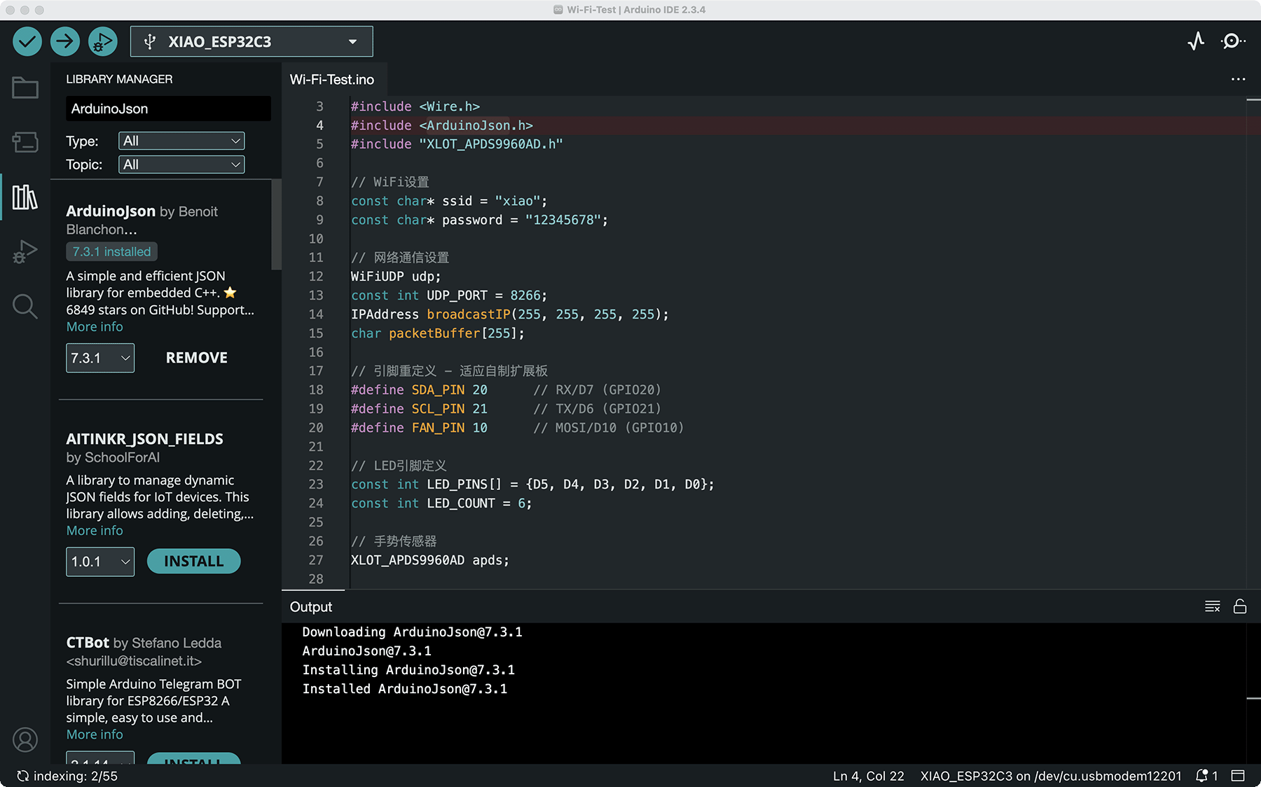
Search for ArduinoJson in the library management interface and install the ArduinoJson library developed by Benoit Blanchon
Manual Installation (if the above method doesn't work)
- Visit the ArduinoJson GitHub repository
- Click the Code dropdown menu, then select Download ZIP
- After downloading, extract the ZIP file
- Copy the extracted ArduinoJson folder to your Arduino libraries folder:
- Windows:
Documents\Arduino\libraries\ - macOS:
~/Documents/Arduino/libraries/ - Linux:
~/Arduino/libraries/
- Windows:
- Restart Arduino IDE
- Recompile your code
If your code uses other uninstalled libraries (such as the XLOT_APDS9960AD library), you'll need to install them in a similar manner.
The built-in Wire.h library
#include <Wire.h> includes Arduino's built-in I2C communication library. You don't need to install any additional libraries, as the Wire library is a standard library built into the Arduino IDE.
It's used for communicating with various sensors and devices via the I2C protocol, such as the APDS-9960 gesture sensor used in our project.
When you install Arduino IDE, the Wire library is already included, so no additional installation steps are needed. You only need to include this header file in your code to use I2C functionality.
4.3 Program Function Description
- Node Identification and Initialization:
- Generate unique node identifiers based on ESP32 chip ID
- Initialize Wi-Fi connection and UDP communication
- Send broadcast messages to find other nodes
- Network Communication Functions:
- Use UDP protocol to implement low-latency communication
- JSON format messages ensure flexibility in data exchange
- Broadcast and point-to-point messages support dual-node communication
- Gesture Control and Command Synchronization:
- Control local device and send network commands after local gesture detection
- Receive remote gesture commands and execute corresponding operations
- Ensure LED states on both nodes remain synchronized
- State Management and Feedback:
- Display connection status and operation feedback through LEDs
- Send periodic heartbeat messages to ensure connection stability
- Automatically synchronize initial state when joining the network
- Handling Network Interruptions:
- Maintain local functionality after communication interruption
- Automatically attempt to rediscover and connect to nodes
- Synchronize state after connection recovery
5. Hardware Implementation
5.2 Layout Considerations
- Wi-Fi Signal Strength:
- Ensure the antenna is properly installed on the XIAO ESP32C3 (signal strength is extremely low without it)
- Ensure both nodes are within Wi-Fi coverage
- Avoid metal objects and other obstacles that may interfere with Wi-Fi signals
- Gesture Recognition Optimization:
- Keep sensor surface clean
- Avoid direct strong light on the sensor surface
- Ensure the sensors on the two nodes don't interfere with each other
- Visual Display Effect:
- Both nodes' LED arrays should be visible simultaneously for easy comparison of synchronization effect
- Use different colored LEDs (red for one node, blue for the other) for easy distinction
I mounted the two sets of devices on two wine bottles.
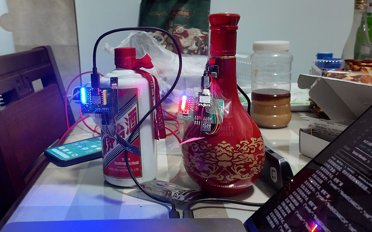
The two sets of devices mounted on two wine bottles
6. System Testing and Demonstration
I mounted the two devices on two wine bottles for testing. I partially covered the sensor part of each device in turn to ensure I was testing whether gestures on different devices could ensure synchronization. Below are the test results:
6.1 Network Connection Test
Both nodes successfully completed the following network connection process after startup:
- Each node successfully connected to the Wi-Fi network and automatically discovered each other through broadcast messages
- LEDs flashed to confirm connection establishment, providing intuitive connection feedback
- When one node's Wi-Fi connection temporarily disconnected, the system was able to automatically reconnect and restore device state synchronization
The average delay observed during testing was approximately 50-80ms, which fully meets real-time control requirements, with the delay having almost no impact on user experience. Under normal Wi-Fi conditions, the packet loss rate remained at a low level, with good communication stability.
6.2 Synchronization Control Test
The LED control synchronization effect was as follows:
- Up swipe gesture: LED count increased synchronously on both devices, with consistent visual feedback
- Down swipe gesture: LED count decreased synchronously on both devices, with consistent visual feedback
- Left swipe gesture (all off): LEDs on both devices turned off simultaneously
- Right swipe gesture (all on): LEDs on both devices all turned on simultaneously
During testing, there were occasional instances of inaccurate gesture recognition, causing some gesture commands not to be recognized, but this was mainly due to limitations of the sensor itself, not network synchronization issues. When gestures were correctly recognized, synchronization control accuracy approached 100%.
6.3 Actual Testing Experience
In actual testing, the system demonstrated good stability and reliability:
- The synchronization delay between the two devices was almost imperceptible, visually presenting an almost simultaneous response effect
- The gesture control interface was intuitive, with up/down gestures adjusting the LED count and left/right gestures implementing all on/all off functionality
- After network disconnection, local functions continued to operate normally, with state automatically re-synchronized after network recovery
- Occasionally, inaccurate gesture recognition led to no response, but this was mainly due to limitations in the sensor's recognition rate
Overall, the tests proved that the system's network communication architecture is reliable, the gesture control mechanism is effective, and the two devices can maintain good state synchronization. Although gesture recognition accuracy is sometimes limited, the system performs well in most cases and successfully implements wireless synchronized control between dual nodes.
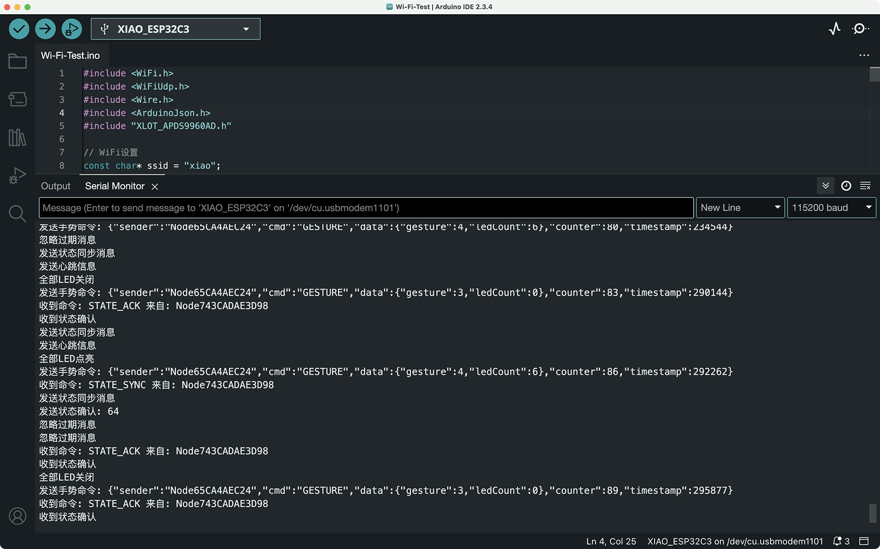
Synchronization data shown in the serial monitor
The actual effect is shown in the video below.
7. Project Issues and Solutions
Issues Encountered
During project implementation, I encountered several major challenges:
- Wi-Fi Connection Stability:
- Issue: ESP32C3 had unstable connections in certain Wi-Fi environments, occasionally disconnecting
- Reason: Wi-Fi signal interference or power fluctuations
- Solutions:
- Added automatic reconnection mechanism, monitoring Wi-Fi status
- Implemented "heartbeat" mechanism to periodically check connection status
- Added LED indication for connection failures
- UDP Communication Reliability:
- Issue: UDP protocol doesn't guarantee message delivery, might lose critical control commands
- Solutions:
- Added simple message confirmation mechanism
- Sent additional state synchronization messages after critical state changes
- Increased periodic broadcasting of state updates
- Gesture Conflict Handling:
- Issue: State conflicts when both nodes simultaneously receive different gestures
- Solutions:
- Used timestamps to resolve conflicts, accepting the most recent command
- Added simple state version number mechanism
- Initiated state synchronization after conflicts
8. Conclusion and Reflection
8.1 Project Results
This project successfully built a dual-node networked gesture control system, achieving the following objectives:
- Designed and implemented ESP32C3-based wireless network nodes, each integrating gesture input and LED output functions
- Created a simple yet efficient UDP communication architecture, enabling automatic discovery and state synchronization between nodes
- Developed an intuitive gesture control protocol, allowing both nodes to respond to gesture commands from either node
- Built a reliable state synchronization mechanism, ensuring system consistency even during network fluctuations
The system demonstrated ESP32C3's powerful networking capabilities and proved the advantages of lightweight UDP-based communication protocols in real-time control scenarios. LED status indicators provided intuitive system state feedback, allowing users to easily understand the system's operational status.
8.2 Relationship to Final Project
This project serves as key technical validation for the "Smart Fantasy Lantern" final project, particularly in the following aspects:
- Wireless Control Validation:
- Verified ESP32C3's Wi-Fi communication capabilities, laying the foundation for remote control of the lantern
- Tested wireless network performance and reliability in real-time control scenarios
- Explored architecture patterns for multi-device collaborative operation
- System Modular Design:
- Verified the feasibility of distributing functions across different nodes
- Provided reference architecture for function separation in the final project
- Demonstrated how to maintain state consistency in a modular system
- Interaction Method Expansion:
- Extended the application range of gesture control from single-device control to networked control
- Verified the feasibility of transmitting complex interaction commands through the network
- Provided technical foundation for future mobile app control integration
- Control Protocol Design:
- Developed an expandable control command protocol capable of supporting more complex lighting effects
- Explored combined control of different control dimensions
- Provided architectural reference for multi-mode control in the final project
These technical validations and architectural designs will be directly applied to the final project, helping me implement a more reliable and feature-rich "Smart Fantasy Lantern" system. Through this dual-node network experiment, I am more confident that ESP32C3 is the ideal platform for implementing lantern network control, and I have gained valuable system design experience.
9. References
- Fab Academy 2025 Network and Communications Course Outline
- ESP32 Wi-Fi Programming Official Documentation
- ESP32 UDP Communication Example
- ArduinoJson Library Documentation
- APDS-9960 Gesture Sensor Datasheet
- XIAO ESP32C3 Official Documentation
- Week 10 Individual Assignment: Gesture-Controlled Mini Fan and LED
- Final Project Concept: Smart Fantasy Lantern