Individual Assignment: Laser Cutting Lantern Shell
Parametric Design and Laser-Cut Interlocking Components
For the parametric design and laser-cut interlocking components section, I designed and created two types of interlocking components featuring elements from traditional Chinese culture. These components were developed using parametric design methods, which fully demonstrates the advantages of laser cutting in creating precise interlocking structures.
Design Concept
I selected two elements with distinctive Chinese cultural characteristics as inspiration for my interlocking component designs:
- Ancient Chinese Coins: The round-outside-square-inside coin shape, which carries rich cultural heritage and symbolic meaning
- Traditional Chinese "Fu" Character: A symbol of good fortune widely used in Chinese culture
These designs not only serve a functional purpose (as interlocking components) but also incorporate cultural elements, making the work more personalized and culturally meaningful.

I selected 2 reference patterns: one is the ancient Chinese coin with its round outside and square inside shape; the other is the traditional Chinese "Fu" (福) character pattern
Parametric Design Process
Ancient Coin Element Design
Based on the group assignment conclusion, the laser cutter's error range is 1.1741mm. I assumed the wooden board I would use for cutting was 2.76mm thick (in fact, it's best to measure the thickness of each new board).
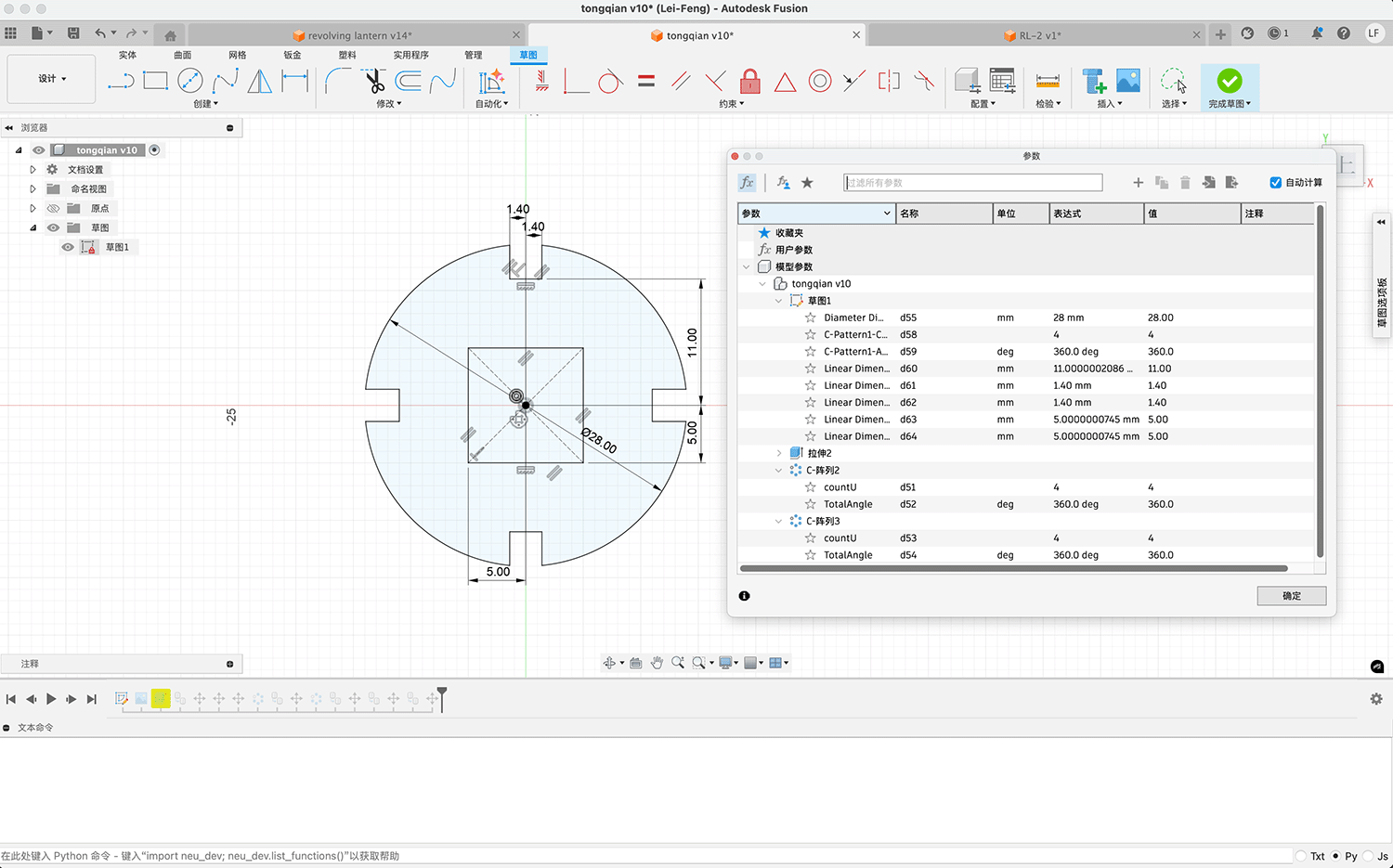
I used Autodesk Fusion 360 for parametric design, creating an interlocking component based on the shape of ancient Chinese coins. The characteristic feature of these coins is their "round outside, square inside" shape, which I maintained in my design:
- Outer circle diameter: 28mm (comparable to most ancient coins)
- Inner square side length: 10mm
- Interlocking slot height: 3mm
- Estimated interlocking slot width: 2.76 - 1.1741 / 2 = 2.17mm
Through parametric design, these dimensions can be easily adjusted to accommodate different usage requirements.
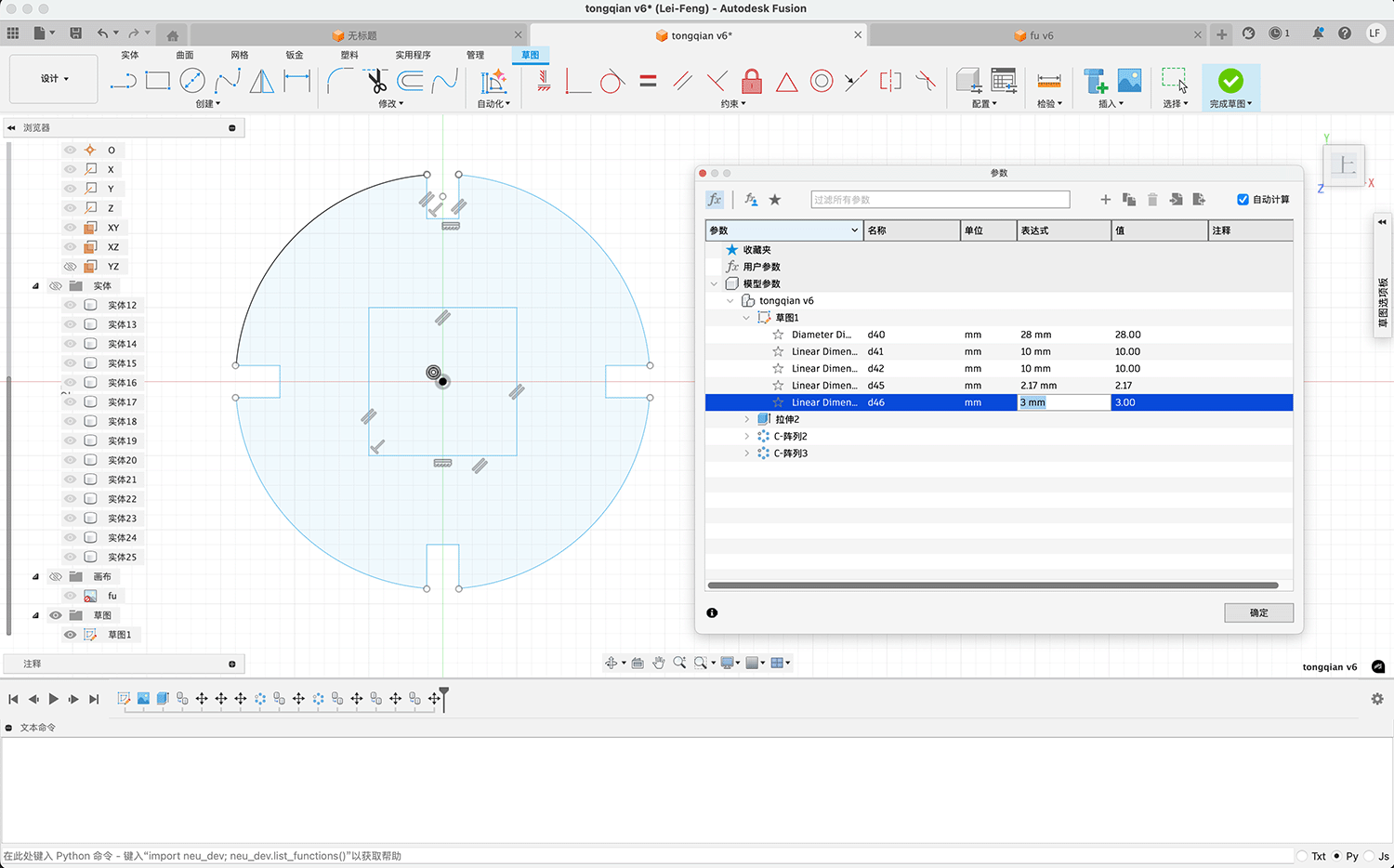
Parametric design of the coin in Fusion, with the parameter settings shown in the right panel
After completing the sketch design, I used extrusion and array functions to simulate the effect of connected coin-shaped interlocking components. I then exported the sketch as a DXF file, as shown below.
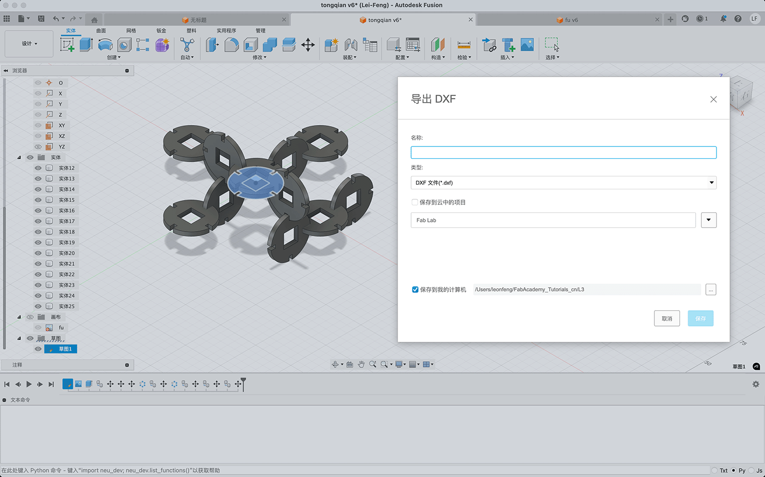
Extruding the coin sketch into a solid, and simulating the coin-shaped interlocking component combination effect through movement, copying, and array, then exporting the sketch as a DXF file
"Fu" Character Element Design
In addition to the coin element, I designed an interlocking component based on the traditional Chinese "Fu" character. The "Fu" design adopts a simplified artistic form, retaining its recognizability while making it suitable for laser cutting. This pattern is relatively large, with an outer diameter of 98mm, interlocking slot width of 2.17mm, and depth of 5mm, as shown below.
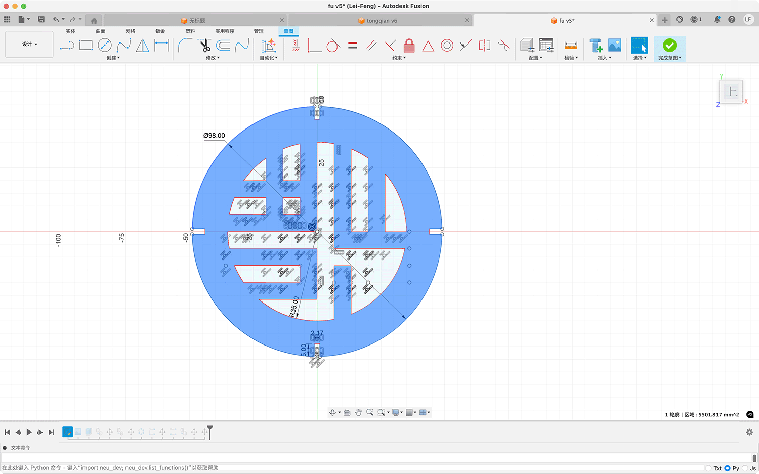
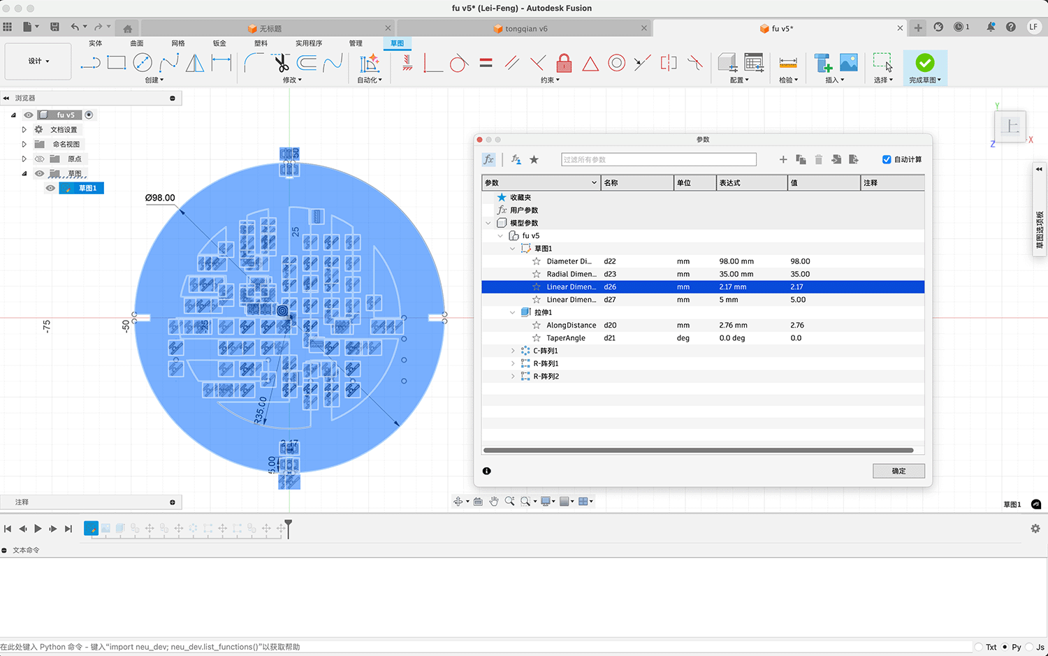
Parametric design of the "Fu" character element in Fusion 360
I extruded the "Fu" character sketch into a solid and simulated the interlocking component combination effect through movement, copying, and array, then exported the sketch as a DXF file, as shown below.
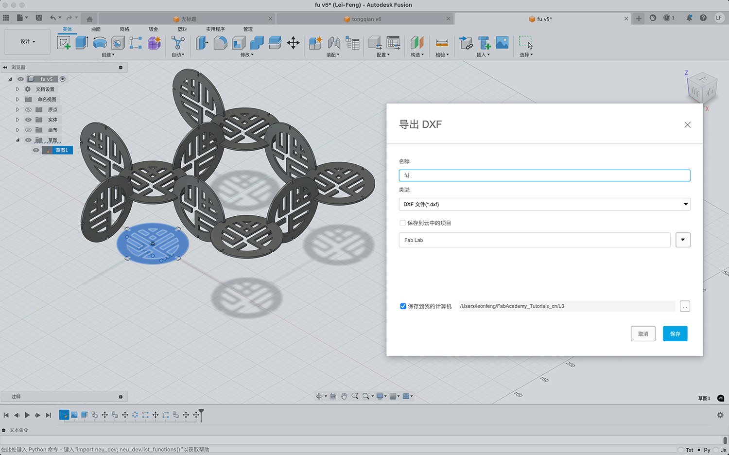
Extruding the "Fu" character sketch into a solid, and simulating the "Fu" character interlocking component combination effect through movement, copying, and array, then exporting the sketch as a DXF file
"Fu" Character File Preparation and Optimization
After completing the parametric designs, I exported the sketches as DXF format files. I then uploaded the DXF files to the computer connected to the laser cutter and imported them into the accompanying software "Laser Engraving and Cutting Control System." Using the Tools/Array Copy function, I set the x count to 4 and y count to 2, resulting in a 4x2 array as shown below.
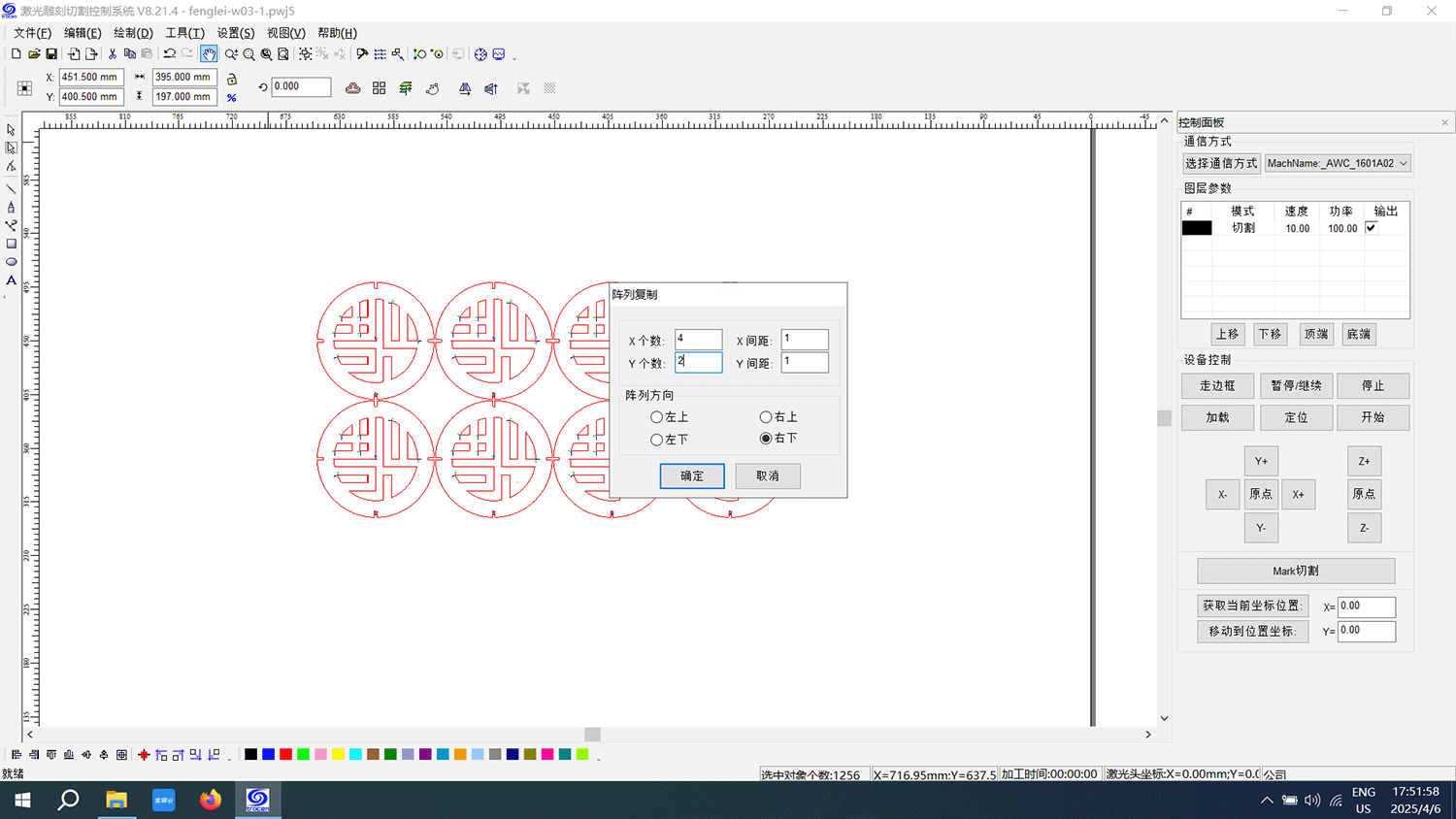
Using the Tools/Array Copy function to create a 4x2 array
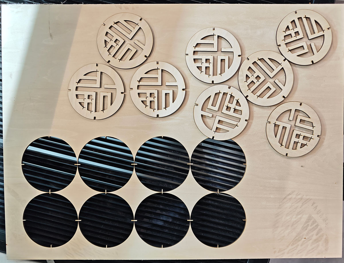
"Fu" Character Laser Cutting Implementation
I then used the "Load" function to send the "Fu" character array to the laser cutter (Dahua Yuming Speed Cut 960B laser cutter) for cutting.
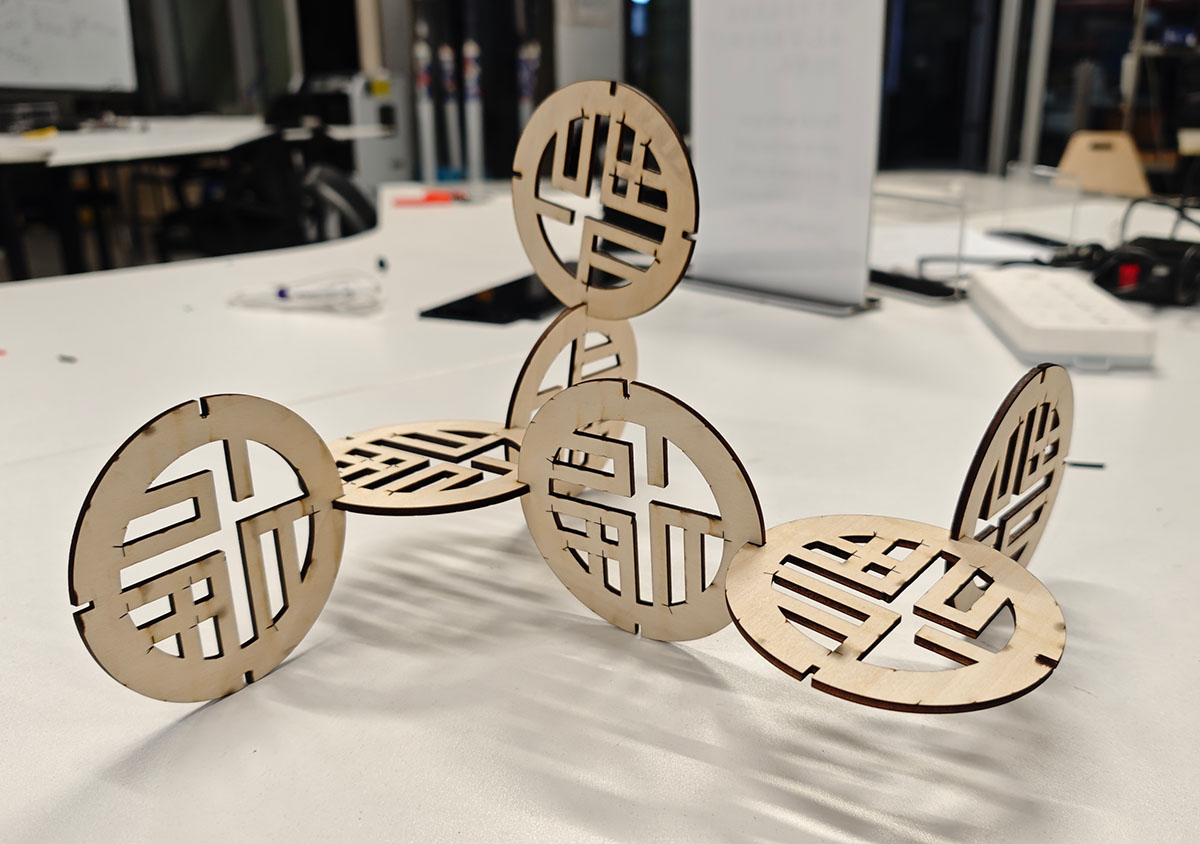
"Fu" Character Assembly and Testing
After cutting was complete, I tested the assembly of the interlocking components. The interface gap seemed a bit small; while the components could interlock, they required significant pressure, making assembly difficult due to their tightness.
Assembled coin element interlocking components
Measurements showed that while the slot width was designed to be 2.17mm, the actual cut width was 2.5mm, which was too small (the actual board thickness was measured at approximately 3.05mm).
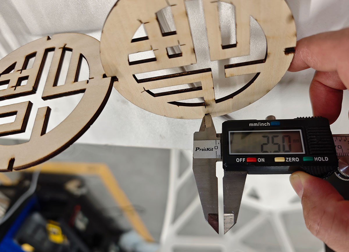
The cut width of the interlocking slot measured 2.5mm, less than the 3mm board thickness
Correcting the Coin Interlocking Design
Due to the insufficient slot gap, I redesigned the coin's interlocking dimensions, adjusting the width from the original 2.17mm to 2.8mm, as shown below.
Setting the coin's interlocking slot width to 2.8mm
This time, I tried cutting two sets of two coins each (one set with 2.17mm width, one set with 2.8mm width) to compare and test the appropriateness of the interlocking slot width.
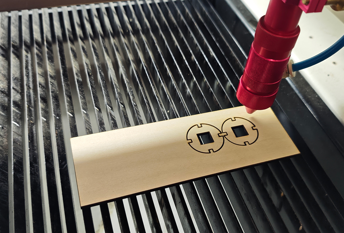
Testing the 2.8mm slot width cut
Upon assembly, I found that the 2.8mm width was just right, with the perfect level of tightness. With a slight amount of force, the components could be securely assembled. In the image below, the left shows the 2.17mm test piece, which could not be fully inserted due to the narrow slot. The right shows the 2.8mm width slot, which allowed complete insertion and interlocking.
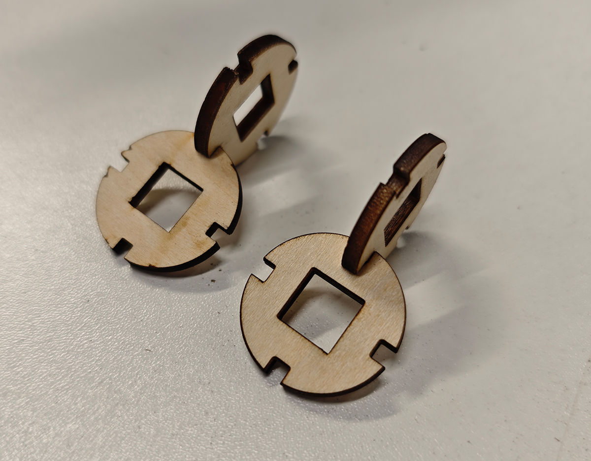
Testing the assembly of 2.17mm width coin interlocking components (left) and 2.8mm width (right). The 2.8mm width was just right, allowing complete interlocking
I then used the Tools/Array Copy function to create and cut 20 copies, as shown below.
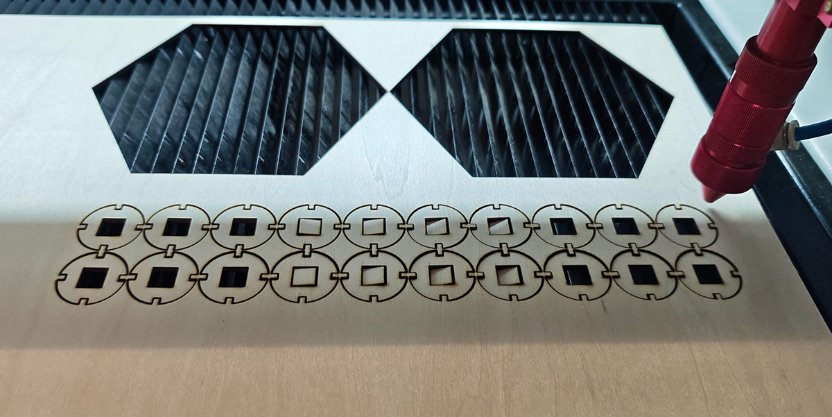
Copying and cutting 20 pieces
This assembly was very successful, with a solid, firm structure and appropriate assembly force.
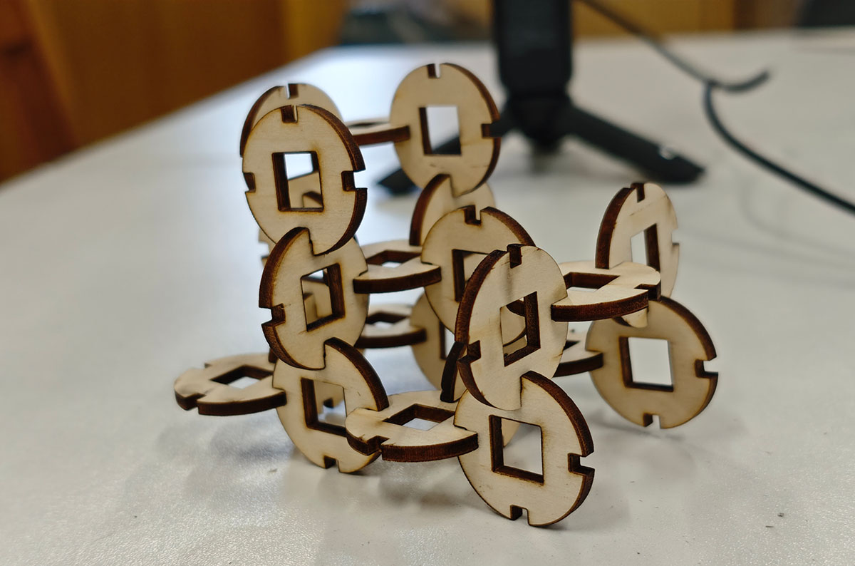
Successfully assembled coin interlocking components
Design Reflection
Through this supplementary project, I further consolidated my skills in parametric design and laser cutting, particularly in the following aspects:
- Cultural Element Integration: Incorporating traditional Chinese cultural elements into modern digital manufacturing technology
- Parameter Optimization: Finding the most suitable interface parameters through testing and adjustment
- Efficiency Improvement: Using the cutting software's Tools/Array Copy function to improve work efficiency
Coin Interlocking Design File Sharing
Coin Fusion design file: https://a360.co/4j0Jw78
Coin interlocking DXF file: tq-2.dxf.zip
Parametric Design of Lantern Shell
In Week 2's assignment: 3D Modeling Smart Fantasy Lantern, I had already attempted to model the lantern shell for laser cutting using Autodesk Fusion software, and exported the sketch as a DXF file) required by the laser cutter, as shown below.

Modeling for laser cutting, exporting the sketch as a DXF format file
Selecting Cutting Material
On February 9, 2025, after completing previous assignments on the computer, I finally started working with the actual equipment. For this assignment, we used the Dahua Yuming Speed Cut 960B laser cutter at Chaihuo Maker Space, as shown below.
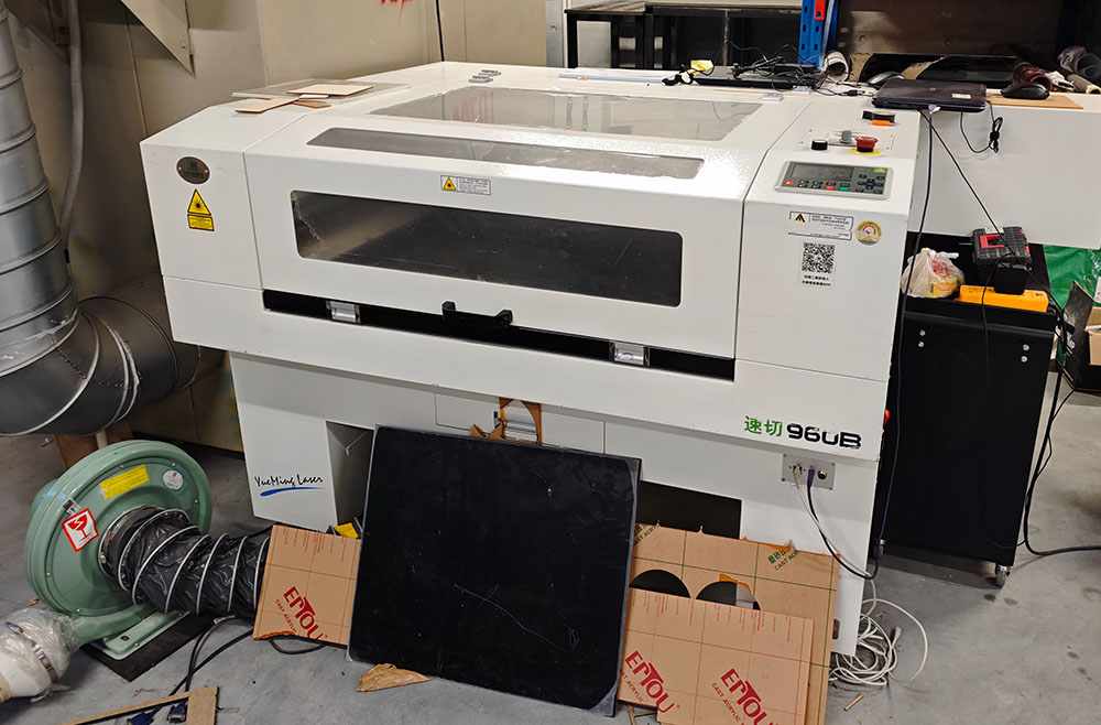
Dahua Yuming Speed Cut 960B laser cutter at Chaihuo Maker Space
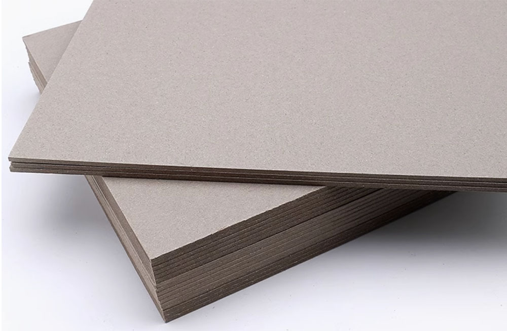
I originally wanted to use 3mm thick wooden boards for cutting, but since it was Sunday at Chaihuo Maker Space and the administrator wasn't present, I couldn't find large wooden boards. After searching for a while, I only found packages of hard gray cardboard, as shown below. Compared to wooden boards, this hard cardboard has much lower strength, but I still wanted to try it to test whether the lantern structure I designed in CAD would match my expectations in size.
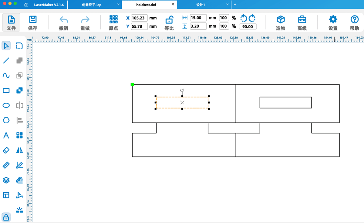
Mortise and Tenon Test
Before cutting the large board (cutting area approximately 38x50 cm), I decided to first create a small mortise and tenon test file. This time I used LaserMaker to draw this small test diagram. The slot was designed for a 3mm board, and I set the slot height to 3.2mm.
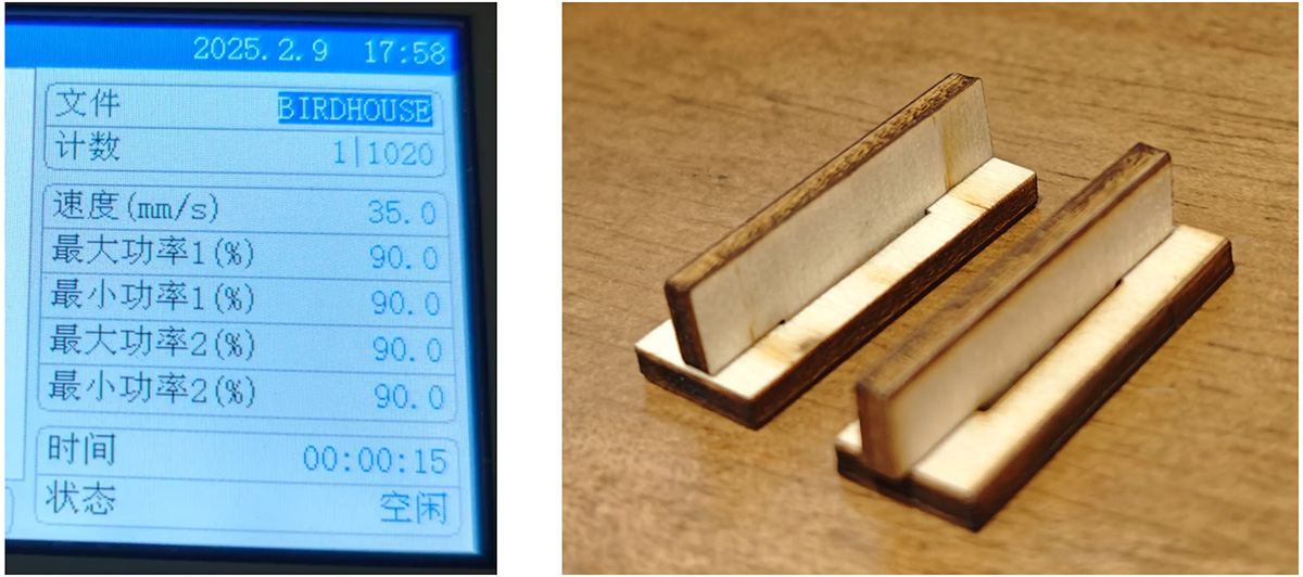
Using the parameters from a previous test ruler (90% maximum power), I first cut this mortise and tenon test material using leftover wooden board. The result was quite good, as shown below. The hole was slightly too large. I thought that if I were to formally cut a 3mm wooden board next time, I would adjust the hole height to exactly 3mm, which should make the mortise and tenon joint more secure.
Then I switched to cardboard. Considering it was cardboard, I set the maximum power to 35%, but found it couldn't cut through. Later, I adjusted it to 70%, which successfully achieved complete cutting, as shown below.
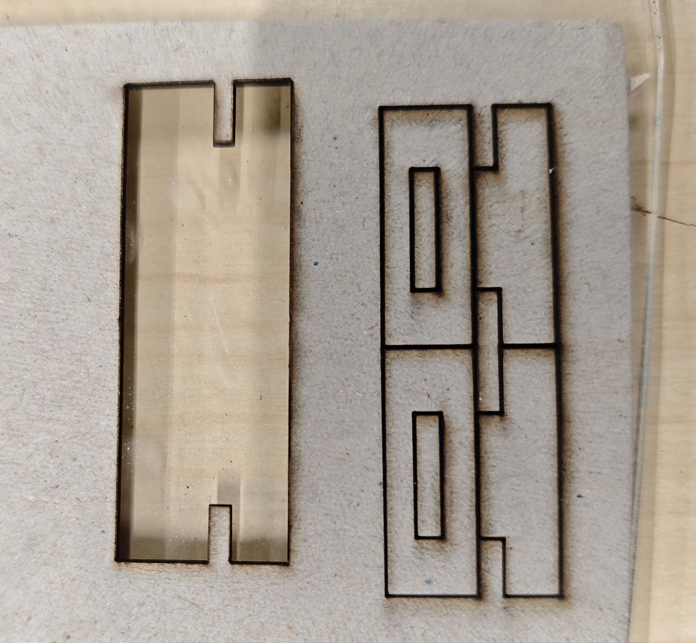
Right side: maximum power set to 35% did not cut through; adjusted to 70% worked well.
After printing was complete, I discovered that the cardboard thickness was less than 3mm, probably only about 1.5mm. The 3.2mm slot left a large gap, as shown below.
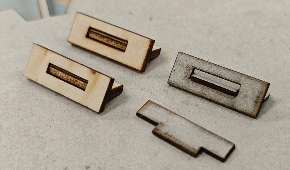
The cardboard thickness was probably only a little over 1mm, so the slot appeared to have a huge gap
Cutting the Lantern Shell
Since this was a test print, I didn't modify the parameters but directly imported the previously designed DXF file into the laser cutter and began cutting using the 70% maximum power setting.
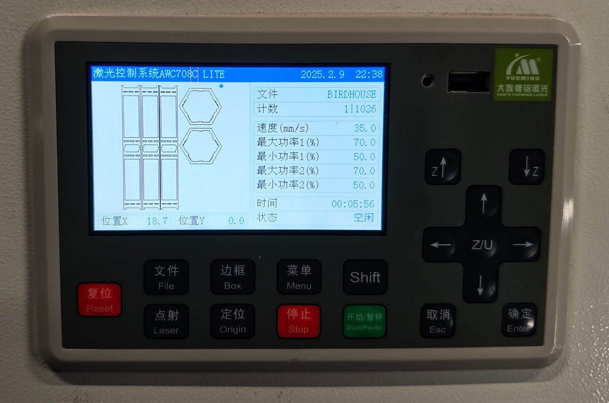
The laser cutter panel showing the file to be cut and cutting parameters
Cutting complete!
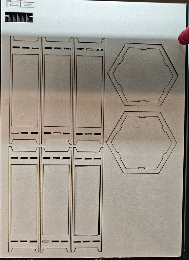
The lantern structure parts just after cutting
Assembling the Lantern Shell
Due to the softness of the cardboard and the oversized mortise and tenon joints, I used a hot glue gun for fixing.
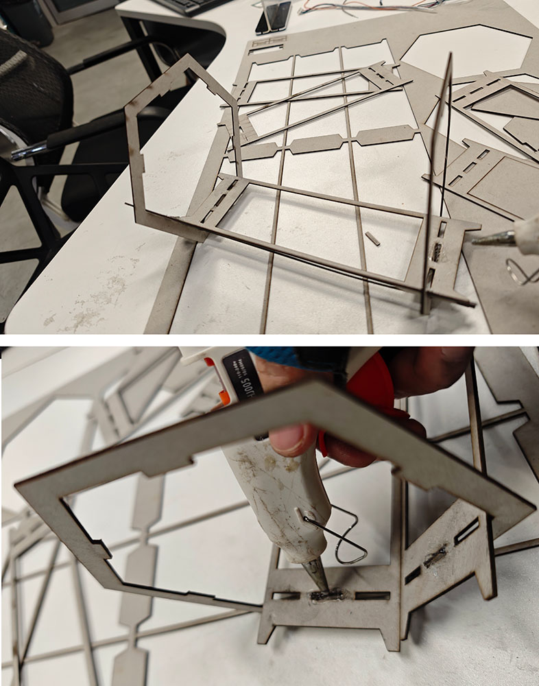
Using a hot glue gun to secure the connection parts
Although not as solid as wooden board, this version 0.1 cardboard structure allowed me to adequately assess the size of the lantern structure.
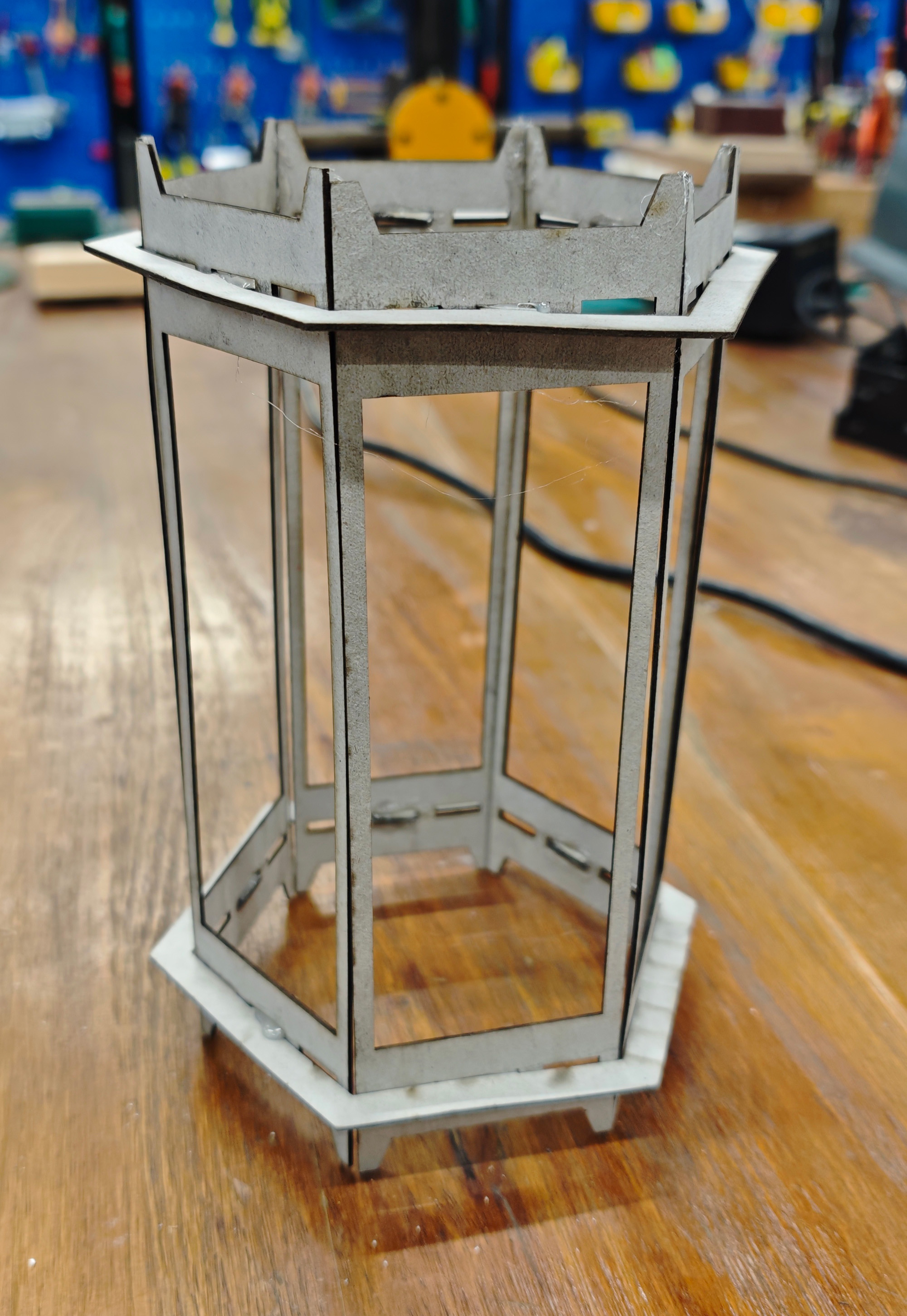
Finished cardboard lantern shell
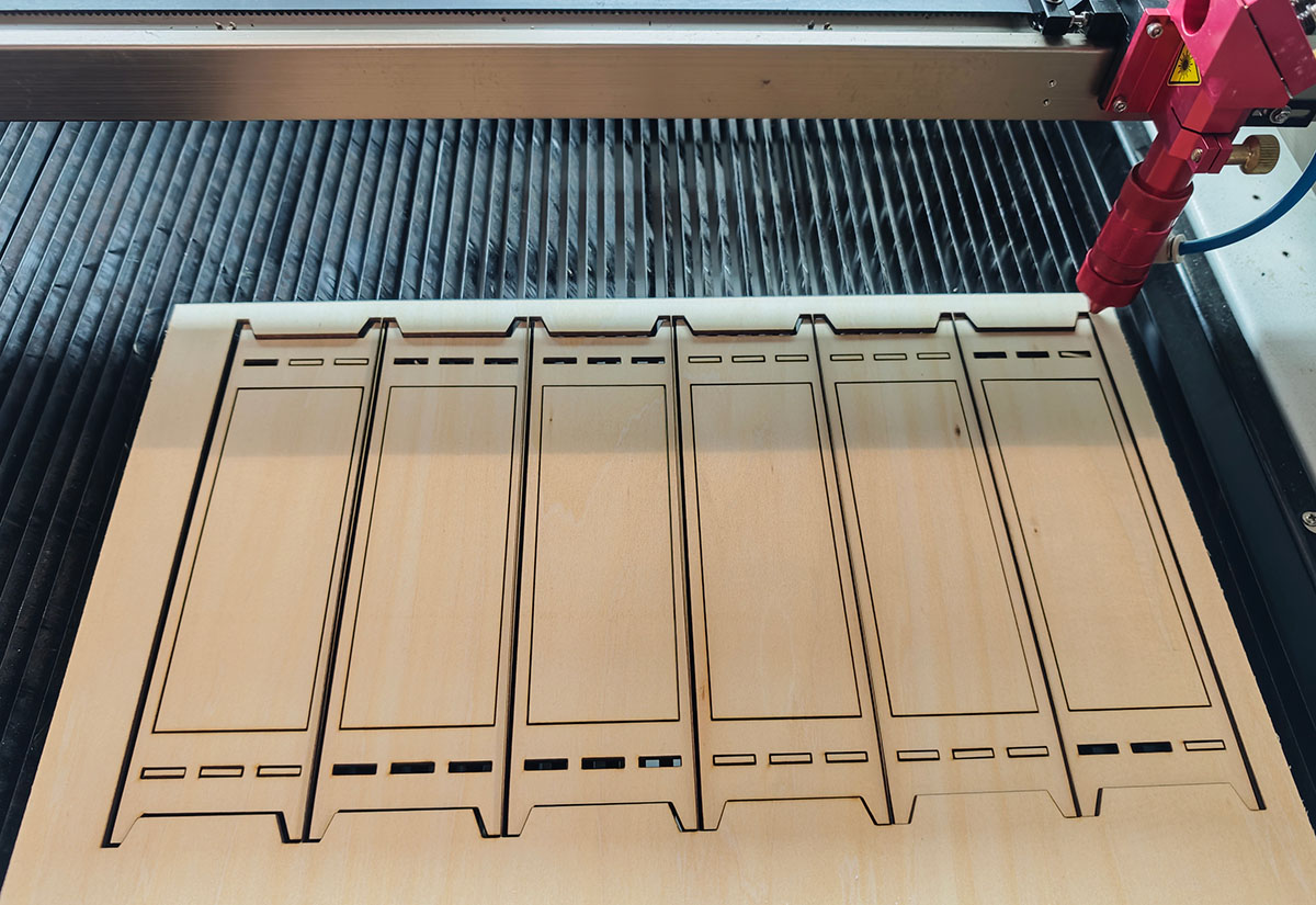
Cutting with Wooden Board
On April 6, after acquiring wooden boards, I used the previous parameters for cutting, as shown below. Everything went smoothly at first.
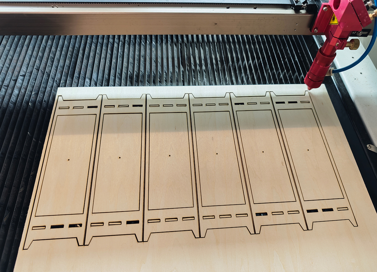
Completed cutting using the previous parameters
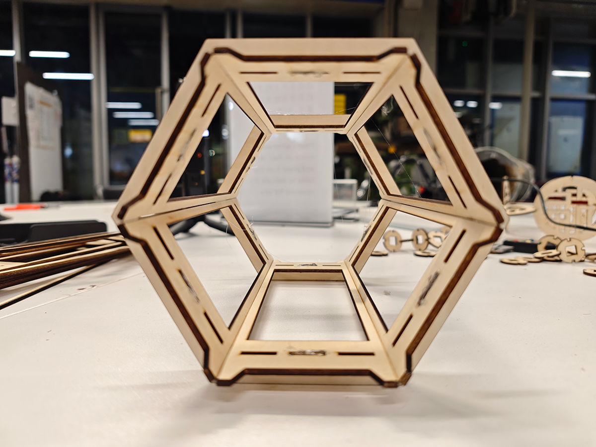
During assembly, I encountered a new problem: the outer frame width I designed was 68mm, which lacked sufficient clearance, making it impossible to insert the last piece—it seemed to be off by just 1mm.
The 68mm outer frame width was too large, preventing the insertion of the last side of the hexagonal frame
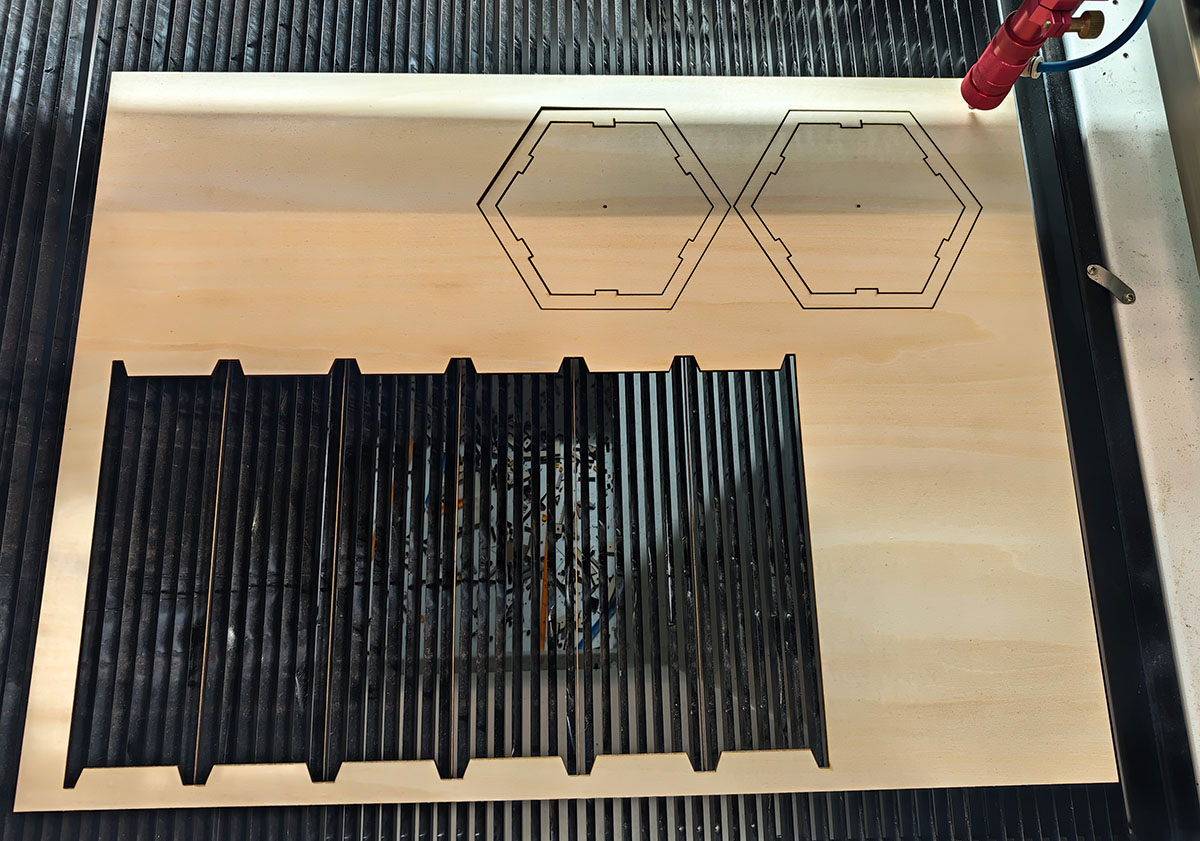
I readjusted the outer frame parameters, setting the width to 67mm. Now I could appreciate the benefits of parametric design.
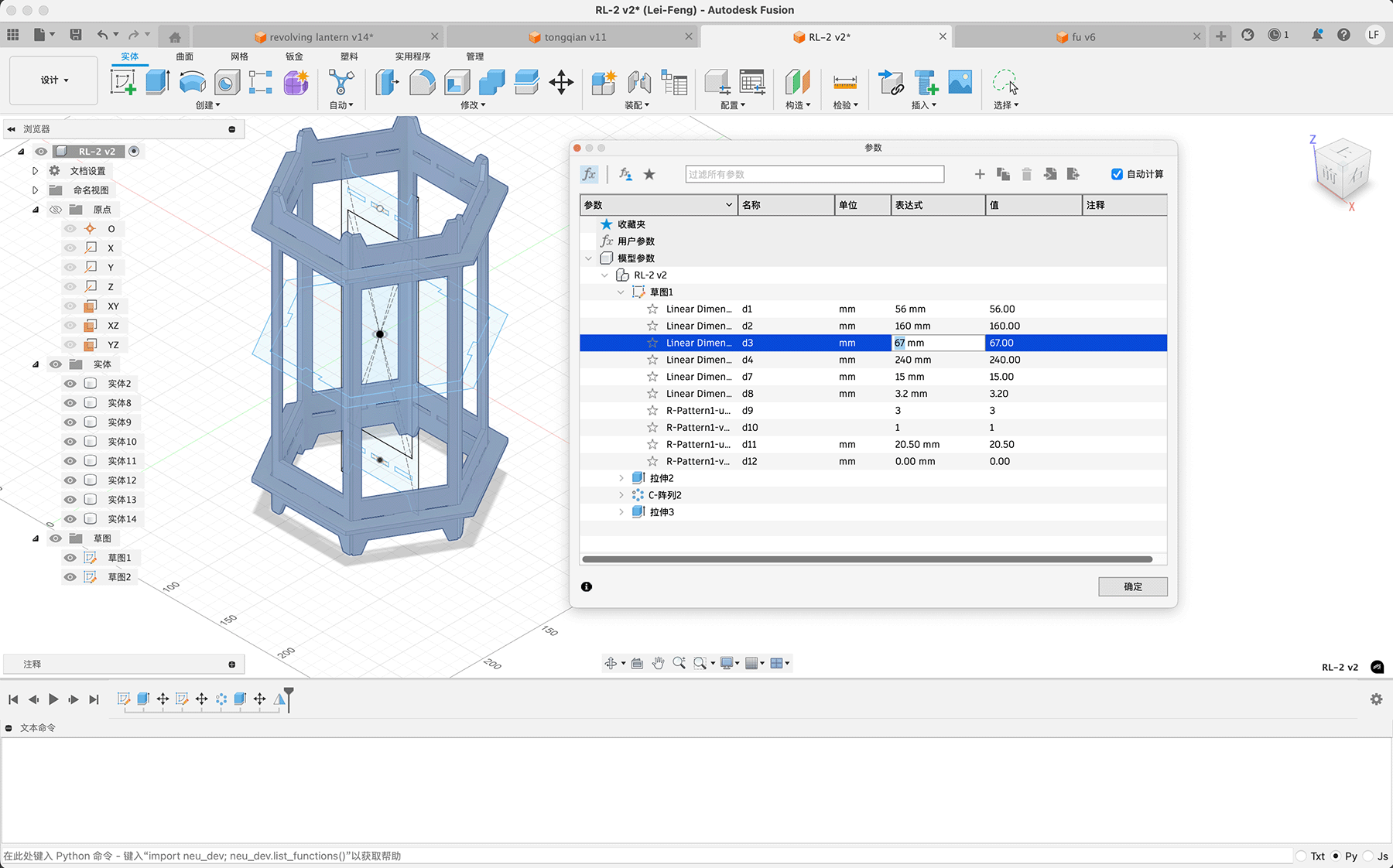
Modifying the outer frame width to 67mm
I exported the DXF again and cut it, as shown below.
Cutting the 67mm width side bars
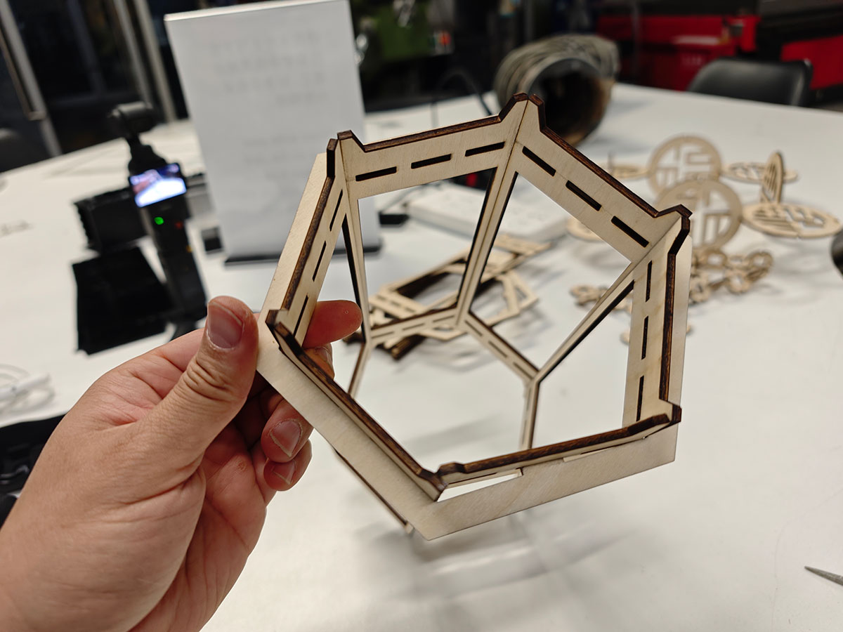
This assembly went very smoothly, with everything fitting precisely. Although it was already quite secure, I still used a hot glue gun to fix the joining parts.
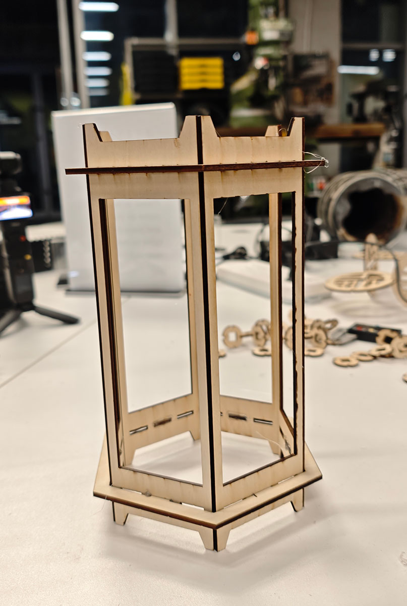
The assembled lantern shell appeared very sturdy.
Lantern Shell Design File Sharing
Lantern shell design file: https://a360.co/3XLW0a9
Lantern shell DXF file: revolving-lantern-dxf.zip