Week 7 Individual Project: Monitor Stand Design and Cutting
The requirement for this class is to design, mill, and assemble a large item (approximately meter-scale), and attempt to do so without using fasteners or glue (bonus points). I decided to create a wide monitor stand for my 1.6m × 0.6m adjustable desk.
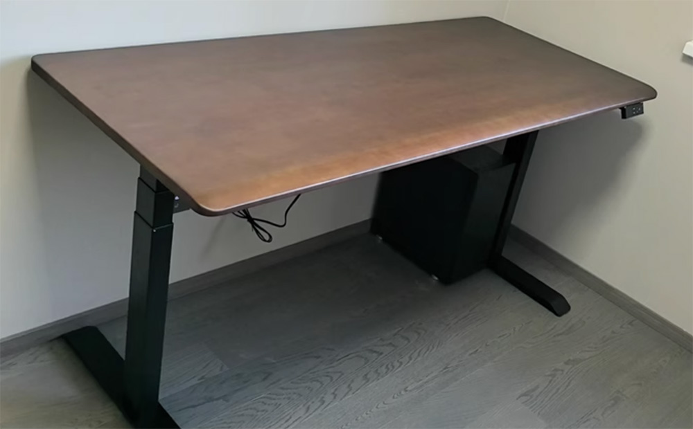
The appearance of my 1.6m × 0.6m adjustable desk. I want to add a monitor stand on the desk to make more effective use of desktop space
Fusion 360 Design Process
Design goal: For a 1.6m × 0.6m computer adjustable desk, design a 1.5m × 0.25m monitor stand with a height of 0.12m.
Parametric Design: Through parametric design, adjustments can be easily made to accommodate processing and fitting issues later, corresponding to different board thicknesses.
Step One: Basic Drawing and Parametric Design
- Create reference desktop
- Enter the sketch environment, create a basic 2D sketch in the top view
- Design a rectangle with dimensions of 1600mm × 250mm as the top plate base
- Add R30.00 rounded corners to the four corners of the rectangle to make the edges more aesthetically pleasing and safe
The sketch design is shown below.
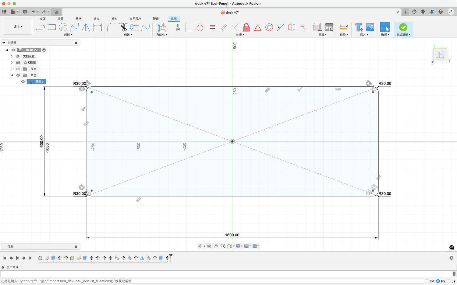
Creating a reference adjustable desktop sketch using parametric design
- Then extrude the reference desktop body. I also specified a wood texture effect, as shown below.
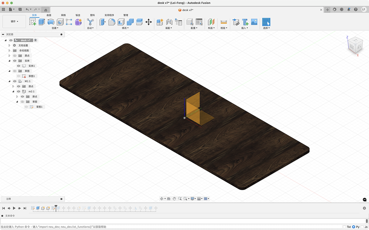
Extruding the adjustable desktop to evaluate the effect of the monitor stand
Step Two: Top Plate Drawing and Feature Addition
- Set key parameters for the top plate sketch
- Length: 1500mm
- Width: 250mm
- Board thickness: 18mm (according to CNC processing specifications)
- Corner radius: R25.00 (four corners)
- Refine the sketch, add necessary connection holes and positioning holes
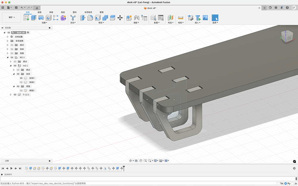
- Draw multiple rectangular holes (40mm × 18mm) at both ends of the top plate for support slot connections. Before cutting, Engineer Xu adjusted the rectangular holes to 46mm × 18mm to facilitate smooth installation
- Set symmetry constraints to ensure balanced design
- Add guide lines and positioning points at the center position
- Add dimension markings
- Total top plate length: 1500mm
- Total width: 250mm
- Connection slot length: 40mm
- Connection slot width: 18mm
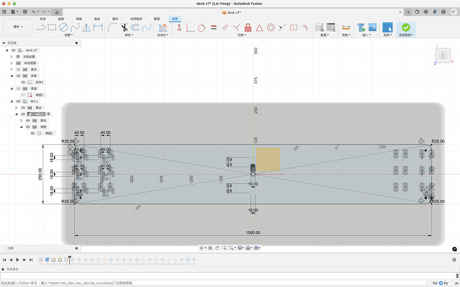
Parametrically designed top plate sketch, with the initial design having embedded board slot holes of 40mm × 18mm
According to actual processing requirements, I adjusted the width of the square slot holes from the original 40mm to 46mm to allow the board material to be inserted smoothly.
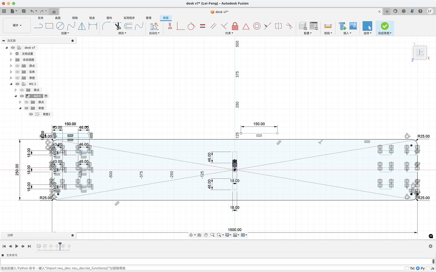
The modified slot holes adjusted to 46×18 mm, and the slot hole depths on the left and right sides were also adjusted to 43mm
- Extrude the top plate
- Select the main body sketch
- Use the "Extrude" command to create a solid
- Set extrusion thickness: 18mm
- Apply appropriate material (wood texture)
Render of the extruded top plate
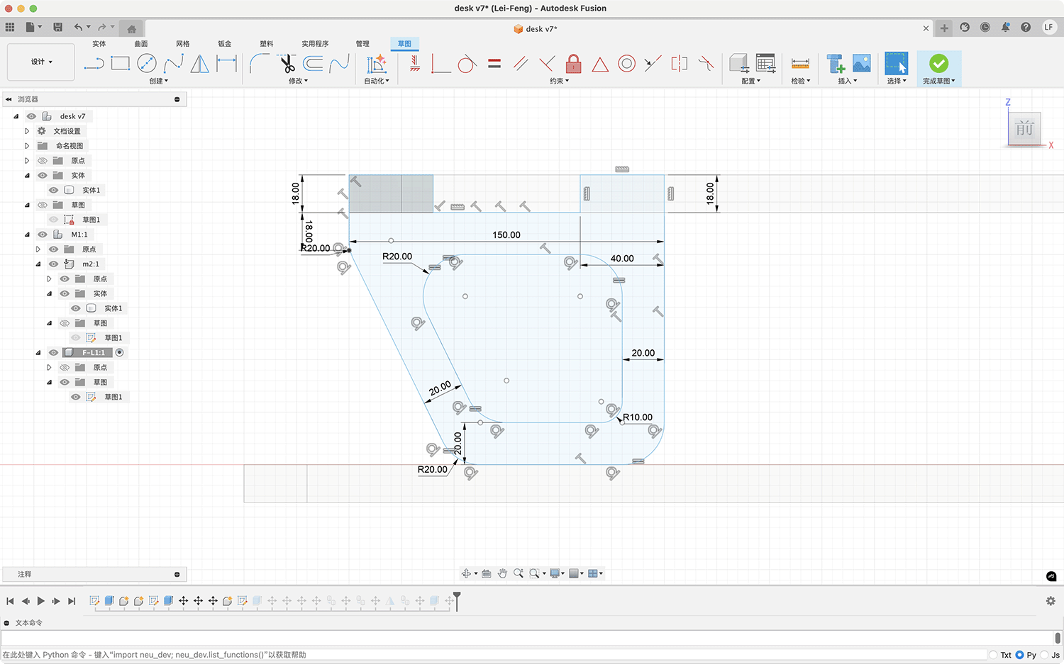
Step Three: Support Design
- Create support sketch
- Draw the support cross-section on an appropriate work plane (xz)
- Design the support shape, creating 2 teeth to stably support the top plate
- Support teeth width: 40mm
- Support teeth height: 18mm
- Support width: 150mm
- Support height: 120mm
- Support internal corner radius: R20.00
- Extrude the support
- Extrude the support sketch to an appropriate thickness
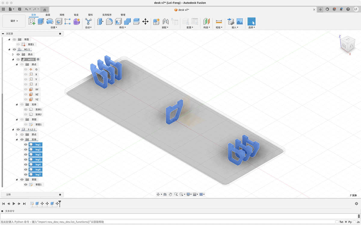
- Copy the support, evenly distribute a total of 7 supports at the bottom of the top plate
- Ensure reasonable spacing between supports to provide sufficient support
Step Four: Overall Effect
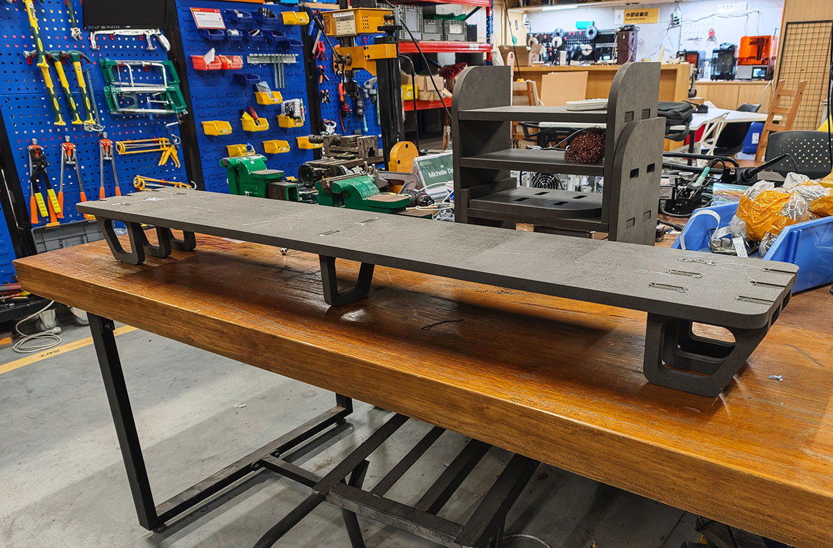
The final completed effect is shown below. The entire structure is connected through board inlays, requiring no additional nails.
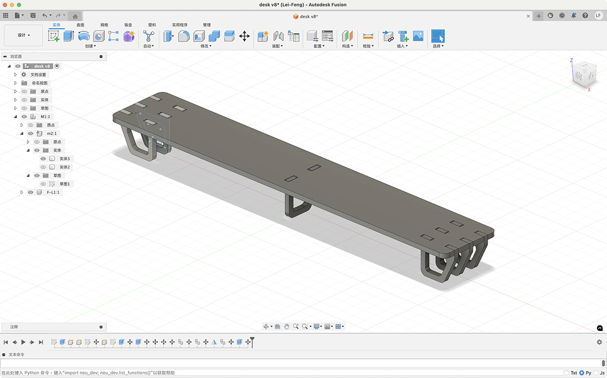
Rendering of the final desktop monitor stand
You can see the traces of reserved width for easy insertion in the rendering
Exporting for Processing Preparation
- Confirm the correct positioning and dimensions of each component.
- Export the design sketches (top plate and supports) as DXF files for CNC processing.
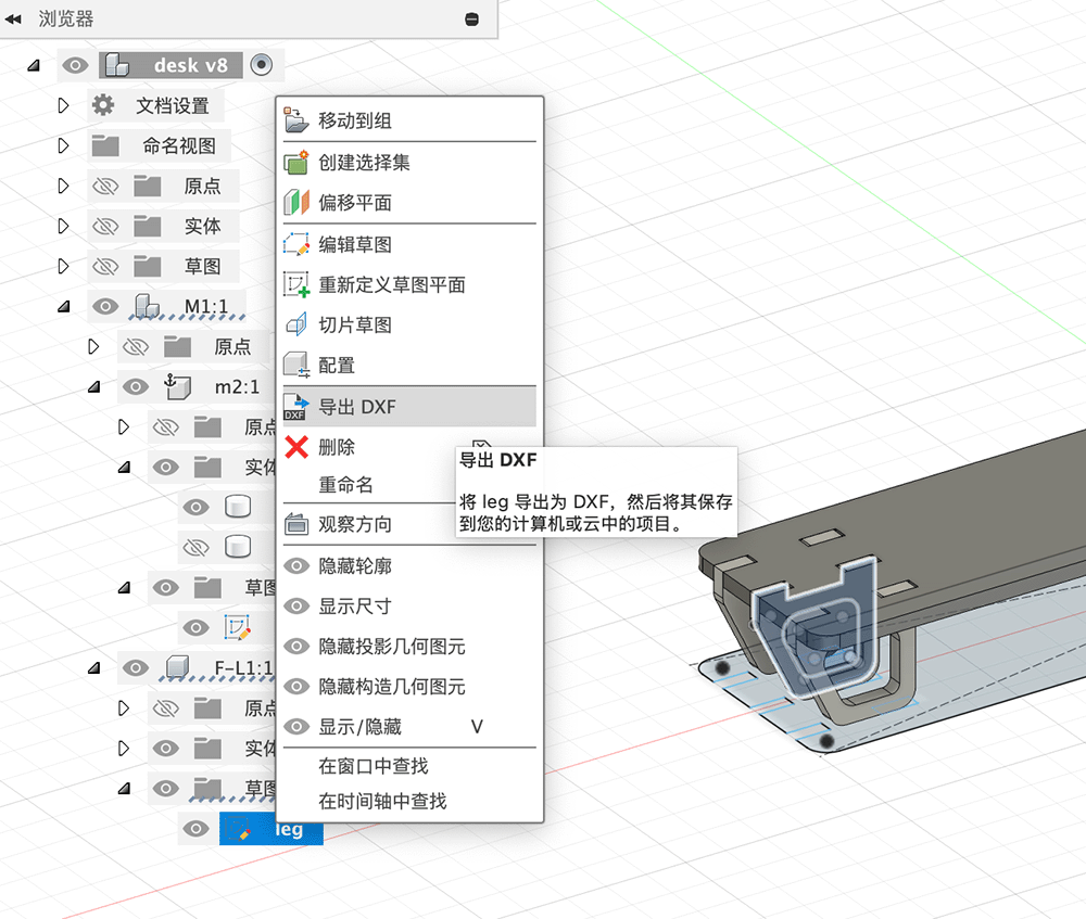
Right-click on the sketch to export the support DXF
Now I have 2 DXF files ready for cutting.
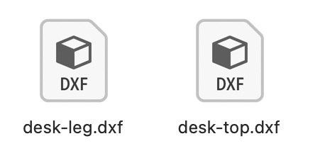
Top plate and support DXF files exported from Fusion sketches
Next, I combined the two DXF files in Adobe Illustrator and arranged the 7 supports needed.
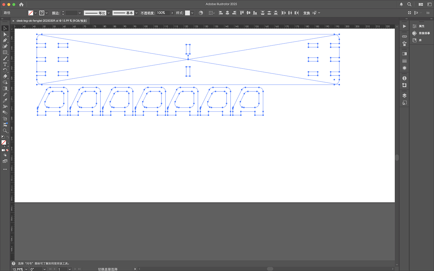
Combining DXF files into one in Adobe Illustrator, and copying and arranging the required number of supports for actual cutting
I finally exported a new DXF file.
MasterCAM X6 Processing Preparation
In MasterCAM, under the guidance of Engineer Xu Guoqun, we performed the following steps:
- Import Design Files: Import DXF files and define the board space, as shown below.
Importing DXF
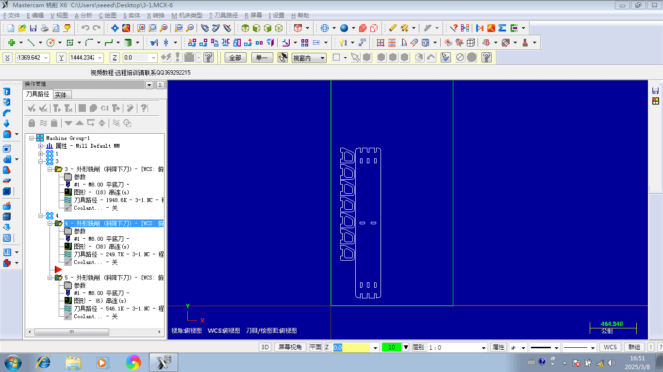
- Layout Processing Design Files and Tool Paths: This part of the work is relatively complex, mostly operated by Engineer Xu while we observed.
Setting up the tool path contour
Setting up the tool path contour
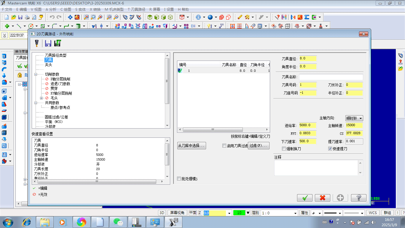
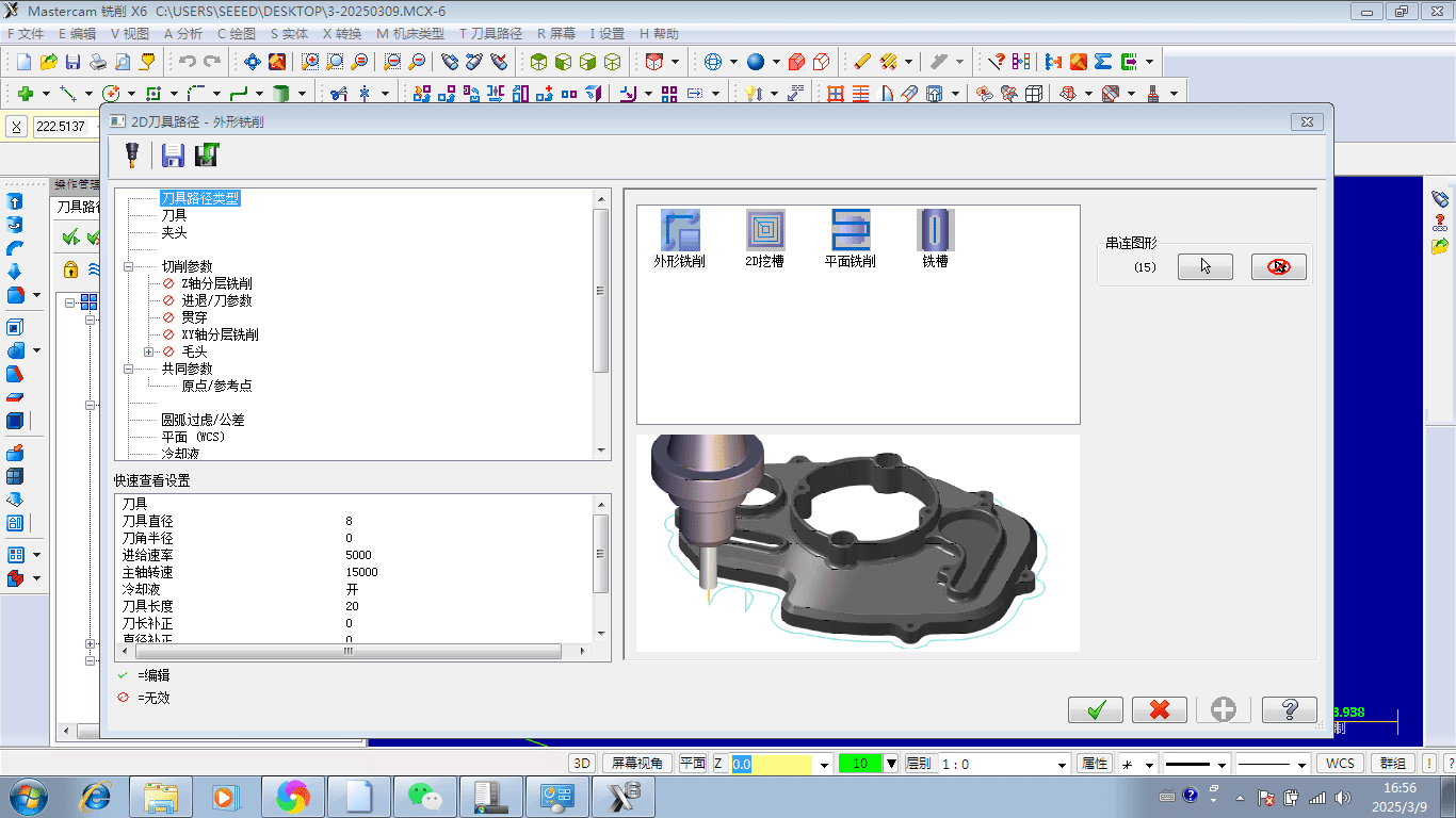
Setting up the tool, including key parameters such as tool diameter 8mm, feed rate 5000, spindle speed 15000, etc.
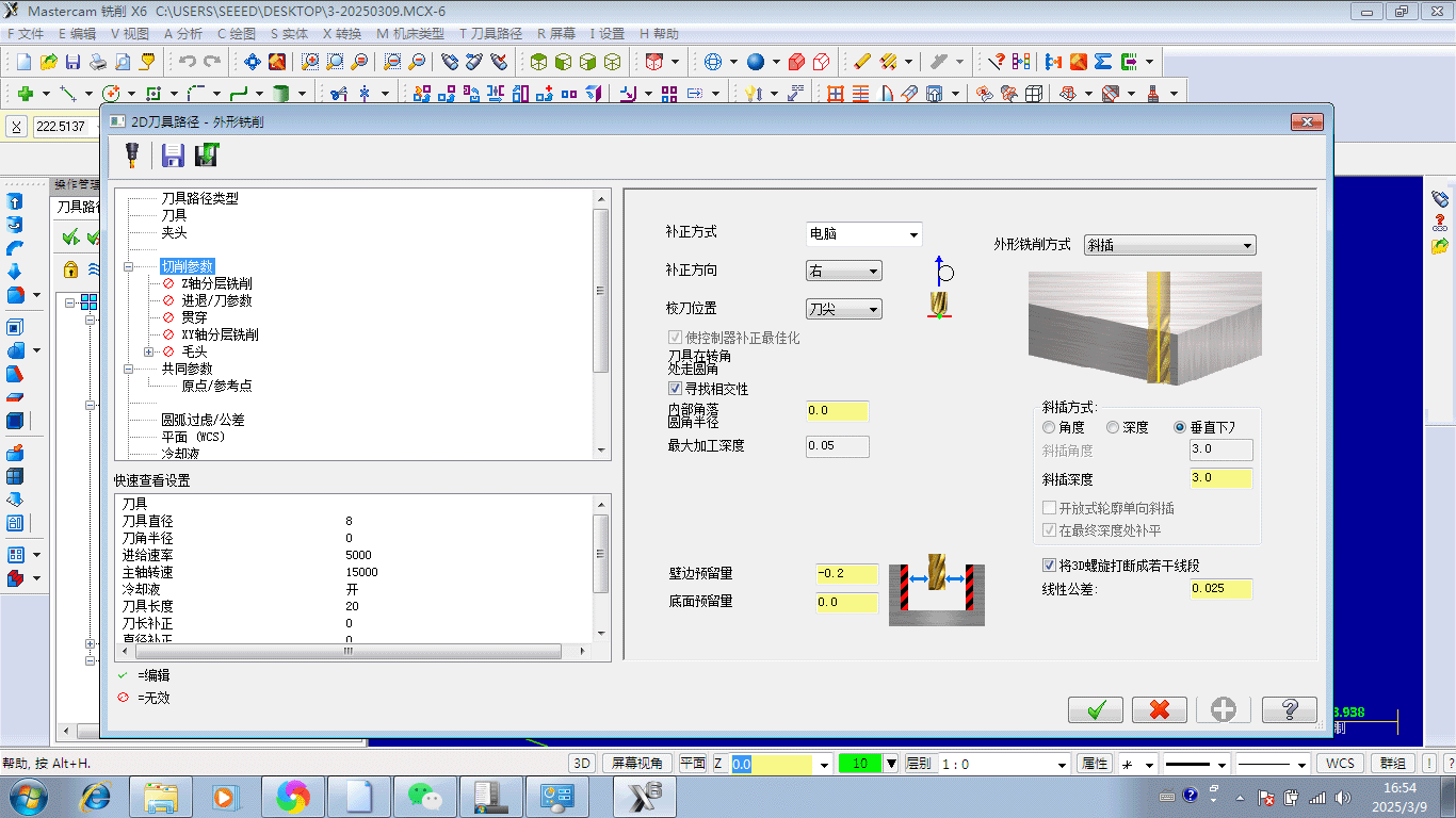
Setting cutting parameters
Common parameter settings for tool contour milling
Tool paths also need to be managed in sequence, arranging the cutting paths according to the "inside to outside, small to large" principle introduced earlier.
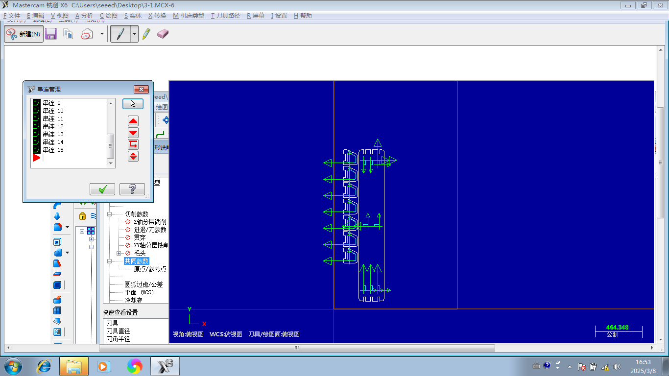
Planning the tool cutting paths
By simulating the tool path, details of the cutting process can be checked. Note that the tool lines for holes that need to be emptied move inward from the lines, while the tool lines for cutting outer contours are outward from the lines. As shown in the simulated tool path below, the cutting process is performed in layers.
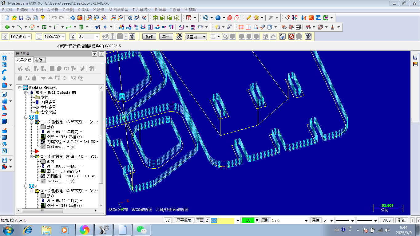
Layered tool cutting path simulation
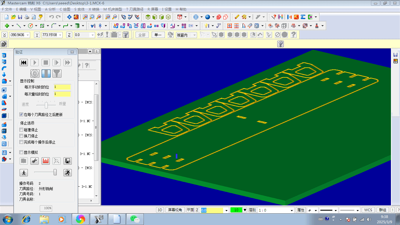
The tool cutting process can be simulated in 3D mode
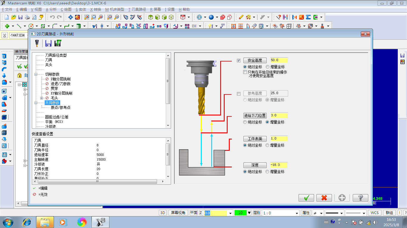
- Set Zero Point: After completing the layout, set the processing zero point.
- Generate Processing Files: After setting the correct parameters, generate the final G-Code processing file.
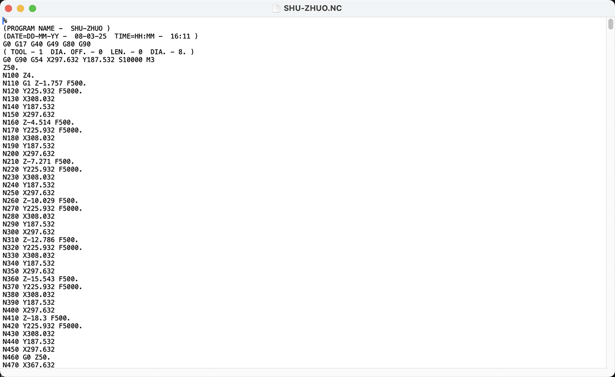
Final G-Code file for CNC cutting my desk
CNC Cutting Process
During the cutting process, we followed these steps:
- Place the Processing Board
- Secure the Board Material
- Adjust the Processing Zero Point
- Turn on the Air Treatment Equipment
- Confirm Processing Settings
- Monitor the CNC Cutting Process
Small parts that lose connection with the main board during the cutting process should be promptly paused (press F10 key), wait for the blade to stop rotating, then remove them, otherwise they may easily damage displaced parts on the last lap.
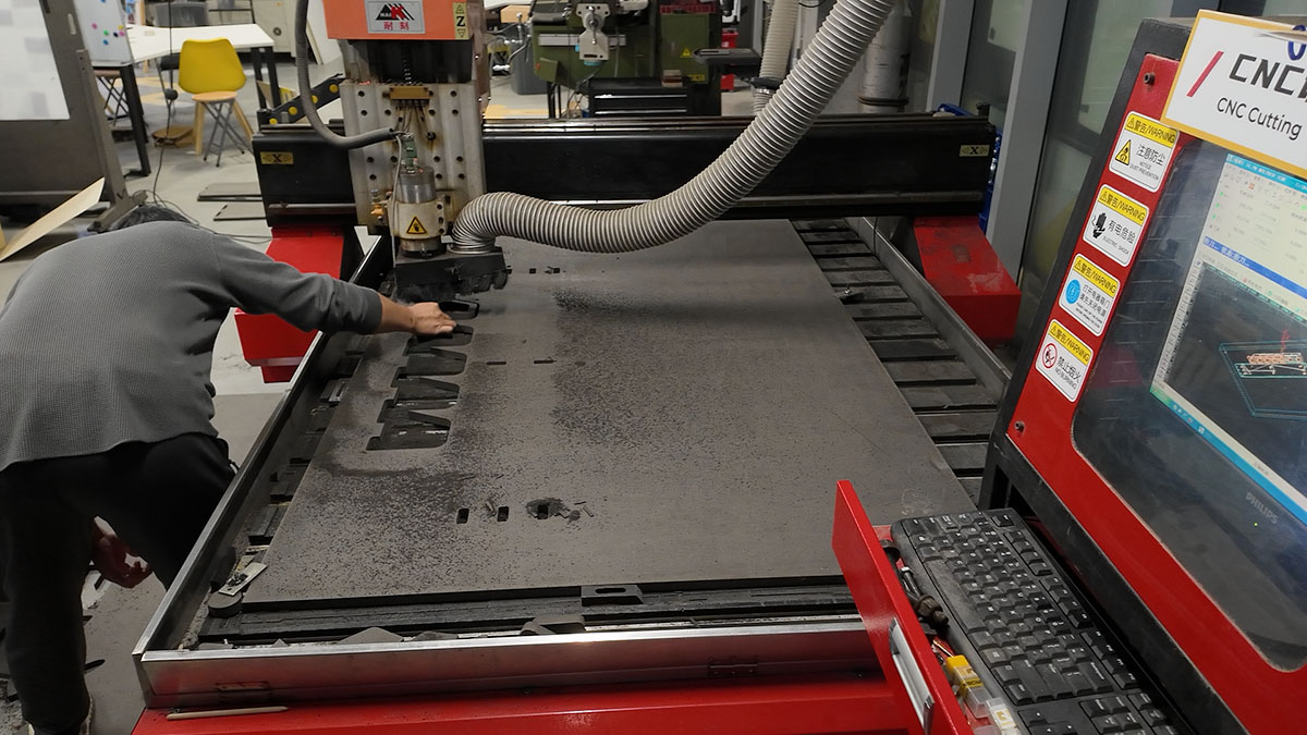
Need to promptly clean small parts that detach from the main board material. Note that moving active parts should be done after pausing and when the drill bit has stopped rotating
- Clean the Processing Area
Assembling the Monitor Stand
After cutting all the parts, I assembled them:
- Check the Parts
- Final Cutting Effect
- Inner Corner Adjustment
- Assembly Connection: Use a rubber hammer to knock the adjusted board materials together to complete the product.
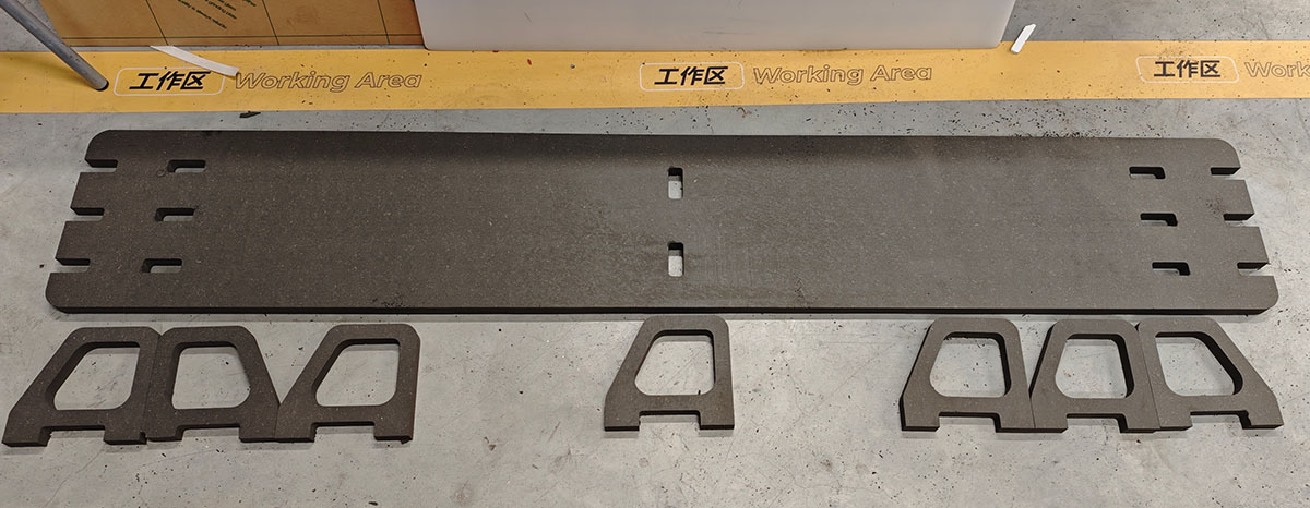
Printed computer desk parts
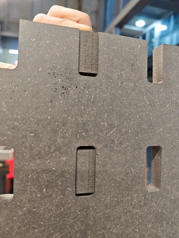
Because of the 3mm allowance above and below, the supporting legs easily fit into the top plate
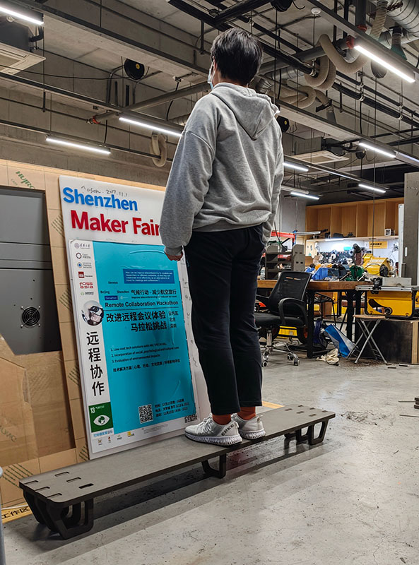
After installation, I tested the support capability, and it's very sturdy
Results Display
I filled the gaps between the stand and the top plate with a hot glue gun to make the support firmly bond with the top plate.
Filled the seams with a hot glue gun. The first piece of furniture I designed and manufactured in my life is complete
I'm very satisfied with the actual use effect.
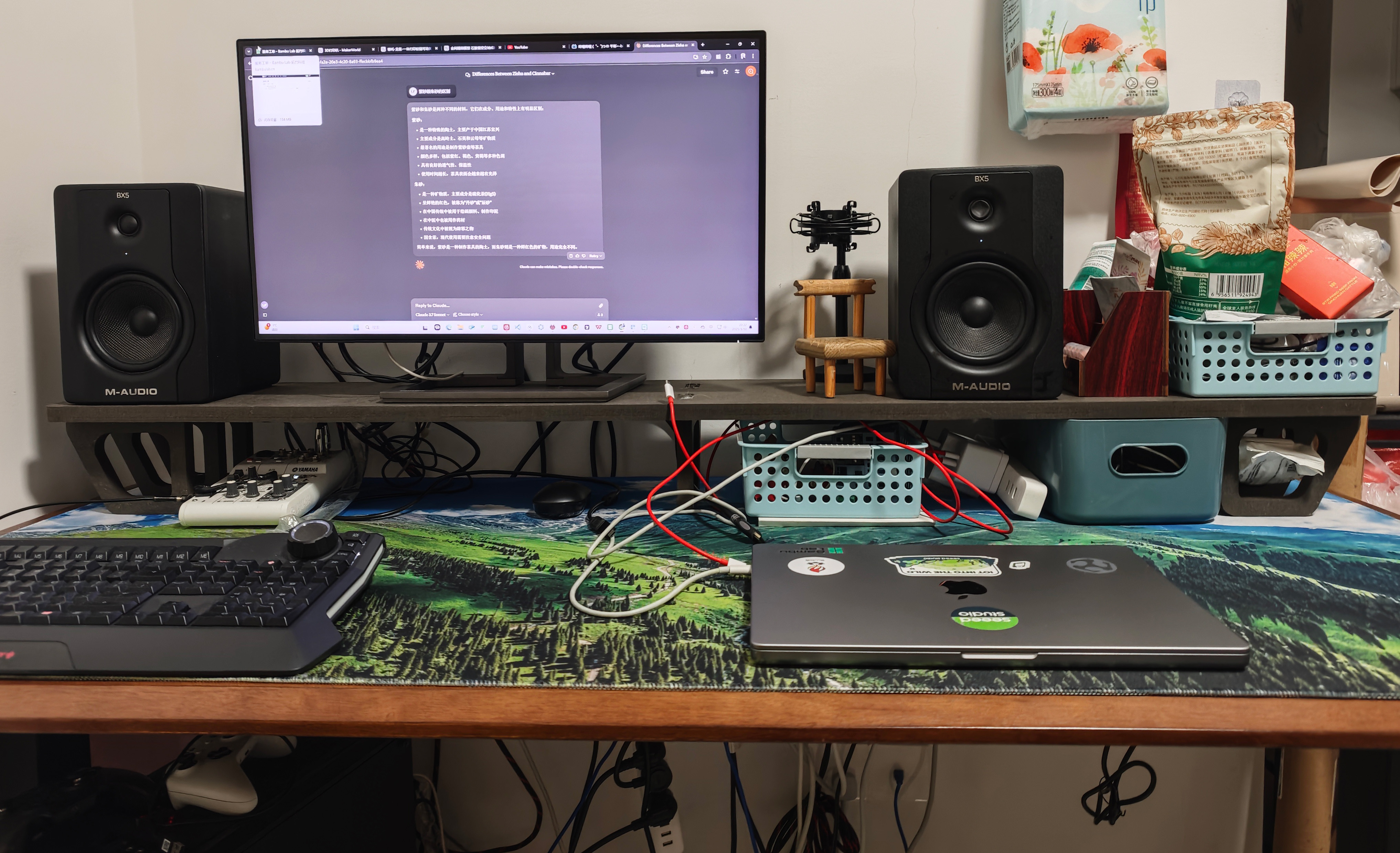
It was put into use immediately, placed on my desktop
Design Source Files
Get my monitor stand Fusion design file: https://a360.co/41OZWJv
Download DXF files and G-Code zip file: Lei-Feng-desk-dxf-nc.zip
Experience Summary
- Design Considering Processing Limitations: When designing, consider the characteristics of CNC processing, avoiding structures that are difficult to process such as inner corners.
- Importance of Tool Selection: Quality tools are essential for successful cutting; soft tools easily break, leading to work interruptions.
- Advantages of Parametric Design: Through parametric design, it's easy to adapt to different material thicknesses and adjust dimensions.
- Inner Hole Design: For small square inner holes that need to be inlaid with board material, the width should be increased by 3mm on both sides to ensure the board material can be inserted.
- Safety First: Throughout the process, safety remains the primary consideration, including wearing proper protective equipment and understanding emergency stop procedures.