Week 10 Individual Assignment: Gesture-Controlled Mini Fan and LED
1. Project Introduction
The main objective of this week's individual project is to add output devices to your designed microcontroller board and program it to work. Based on my previous gesture sensor integration and final project concept, I decided to design a gesture control system that combines an input device (APDS-9960 gesture sensor) with output devices (Grove mini fan and onboard LEDs) to create an interactive electronics project. In my final project, the mini fan's motor will be used to drive the lampshade rotation, so this experiment has important technical validation value for my final project.
Specific project goals include:
- Design and implement circuit connections for gesture-controlled fan and LEDs
- Write a program to implement control functions based on different gestures
- Test the reliability and response speed of gesture recognition
- Explore methods of interacting with multiple output devices
2. Materials and Equipment
Hardware Components
- XIAO ESP32C3 development board (self-made)
- APDS-9960 gesture sensor module (XLOT brand)
- Grove mini fan module
- Connection wires/Dupont cables
- USB data cable
- Power adapter (5V/2A)
Software Tools
- Arduino IDE
- XLOT_APDS9960AD library (for gesture sensor)
3. System Design
3.1 Interface Challenges and Solutions
When adding the gesture sensor and fan module to my custom XIAO ESP32C3 extension board, I faced a key challenge: my designed extension board did not directly expose I2C interface (SDA/SCL) pins.
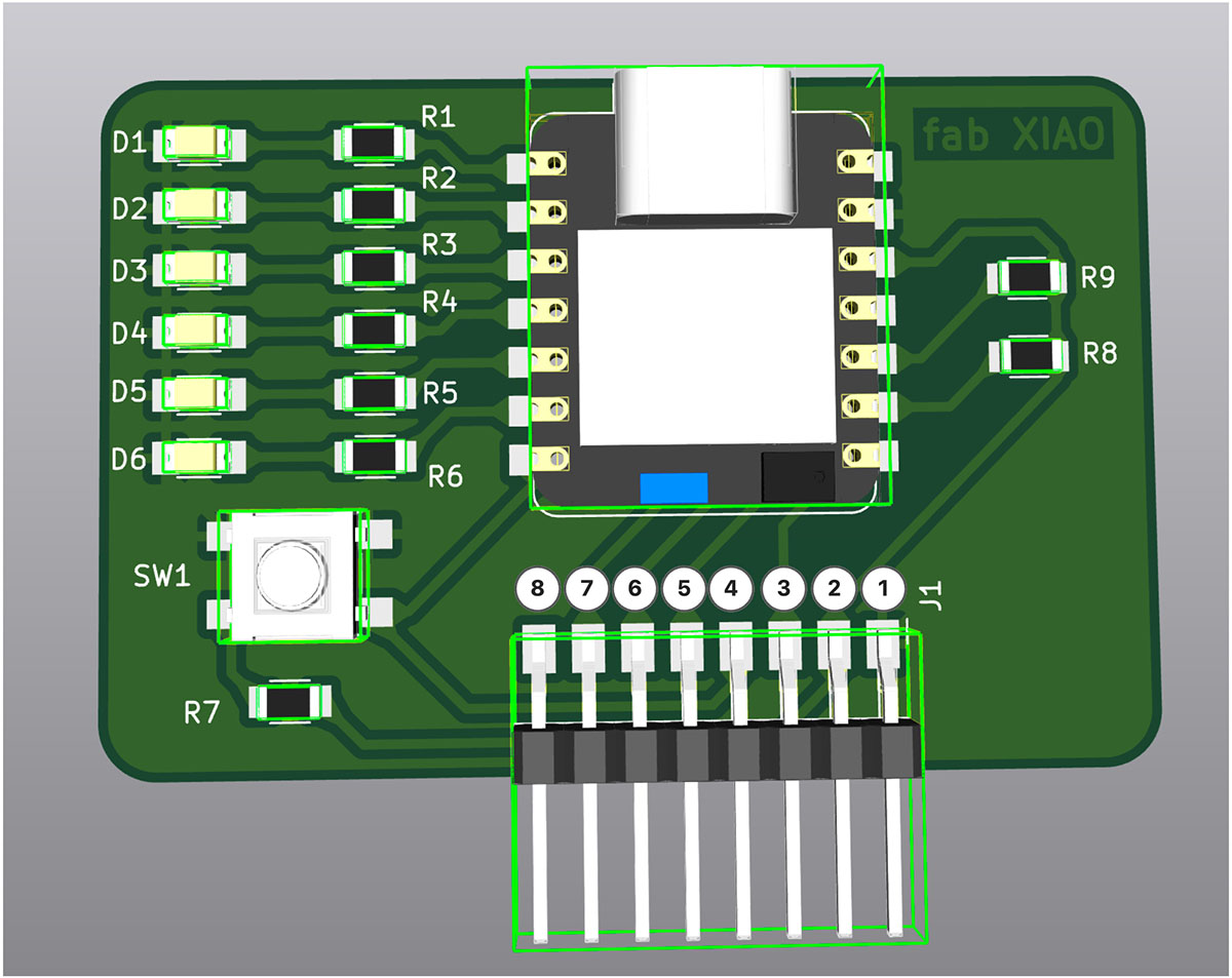
The 8 pins on my XIAO development board are shown in the figure below.

Pin labeling of my designed XIAO development board
Functions of the 8-pin connector (J1) on the XIAO ESP32C3 extension board:
| Pin Number | Label | Function | GPIO Number |
|---|---|---|---|
| 1 | GND | Ground connection | - |
| 2 | 3.3V | 3.3V power output | - |
| 3 | RX/D7 | Serial receive pin | GPIO20 |
| 4 | TX/D6 | Serial transmit pin | GPIO21 |
| 5 | SCK/D8 | SPI clock signal | GPIO8* |
| 6 | MISO/D9 | SPI master in slave out | GPIO9* |
| 7 | MOSI/D10 | SPI master out slave in | GPIO10 |
| 8 | RST | Reset signal or other function extension | - |
Note: Pins marked with * are Strapping pins, used for ESP32C3 boot mode selection.
To address this limitation, I used ESP32C3's software I2C functionality, solving the problem by remapping pins:
- Using RX/D7(GPIO20) as SDA data line
- Using TX/D6(GPIO21) as SCL clock line
- Using MOSI/D10(GPIO10) as fan control pin
Additionally, the development board already has 6 LEDs (D0-D5), which I can directly use as visual feedback output devices.
3.2 Functional Design
The gesture control system will recognize four basic gestures through the APDS-9960 gesture sensor and control the fan and LEDs:
| Gesture Direction | Control Function |
|---|---|
| Right swipe | Turn on the fan |
| Left swipe | Turn off the fan |
| Upward swipe | Increase the number of lit LEDs |
| Downward swipe | Decrease the number of lit LEDs |
This design makes operation more intuitive:
- Left/right gestures control the fan's start/stop
- Up/down gestures control the number/brightness of LEDs, symbolically representing fan speed levels
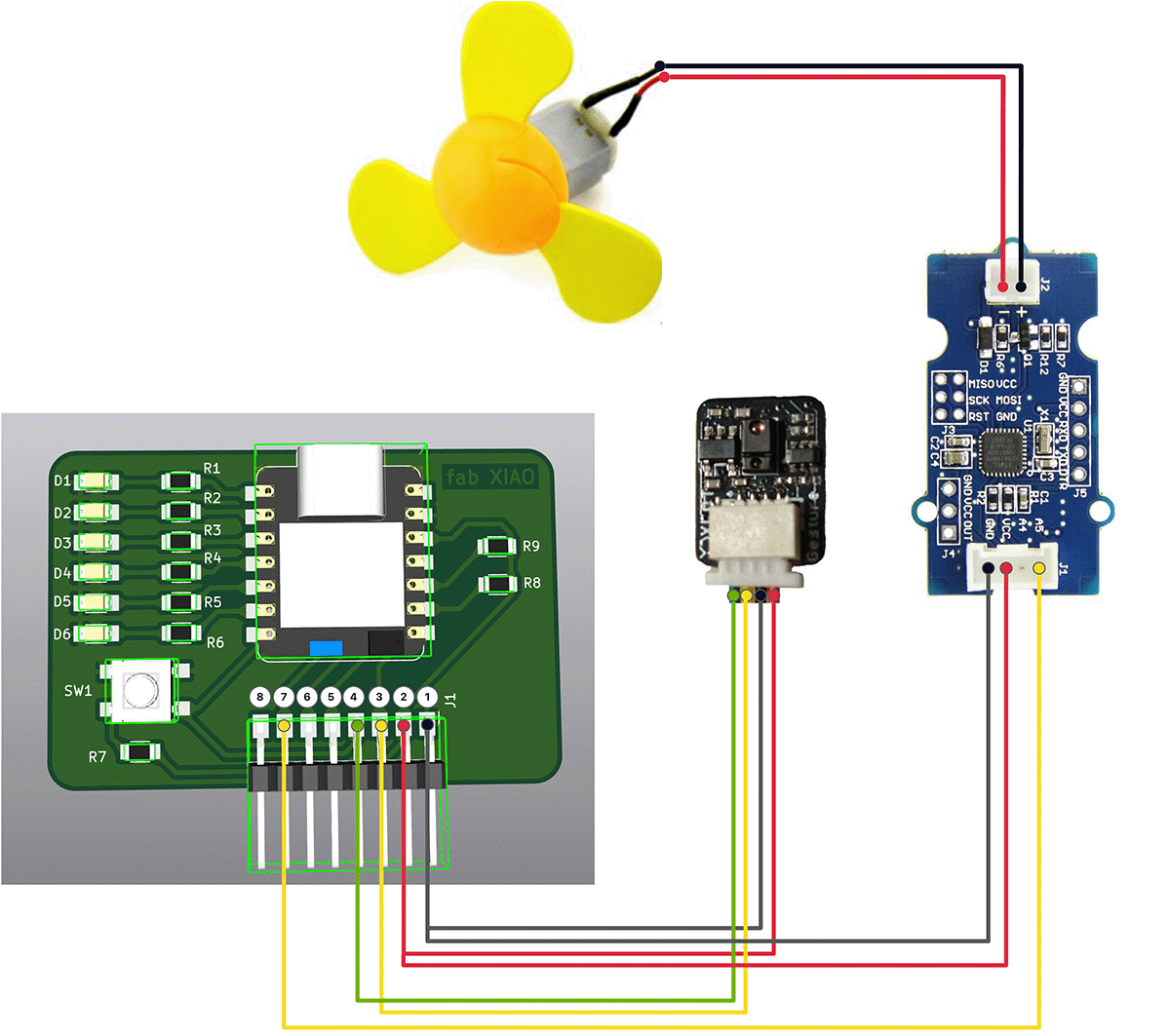
3.3 Hardware Connection Design
Power and Ground Sharing Solution
Since both devices need to be connected to power and ground, while the J1 interface only has one set of 3.3V and GND pins, I adopted a Y-type splitter connection to solve this problem:
- Creating Y-type splitter connectors:
- Using Dupont wires to make two simple Y-type splitters
- One for 3.3V power supply (pin 2), another for GND (pin 1)
- Each Y-type splitter expands one pin into two interfaces
- Alternative solutions:
- Could also directly use additional GND and 3.3V pins on the XIAO ESP32C3 board
- Or use a breadboard for power distribution
Modified Device Connection Scheme
APDS-9960 Gesture Sensor Connection
| APDS-9960 Pin | Connected to Extension Board Pin | XIAO ESP32C3 Pin | Function |
|---|---|---|---|
| VCC (red wire) | J1-2 (3.3V) Y-splitter | 3.3V | Power positive |
| GND (black wire) | J1-1 (GND) Y-splitter | GND | Power ground |
| SDA (yellow wire) | J1-3 (RX/D7) | GPIO20 | I2C data line (software implementation) |
| SCL (green wire) | J1-4 (TX/D6) | GPIO21 | I2C clock line (software implementation) |
Grove Mini Fan Connection
| Grove Mini Fan Pin | Connected to Extension Board Pin | XIAO ESP32C3 Pin | Function |
|---|---|---|---|
| Signal wire | J1-7 (MOSI/D10) | GPIO10 | Control signal |
| VCC | J1-2 (3.3V) Y-splitter | 3.3V | Power positive |
| GND | J1-1 (GND) Y-splitter | GND | Power ground |
LED Connection
The development board already has 6 LEDs (D0-D5), which are directly connected to the corresponding ESP32C3 GPIO pins through the onboard circuit, requiring no additional connections.
3.4 Circuit Connection
System hardware connection diagram, including gesture sensor, fan control, and LED indication.

Connection diagram showing how to use Y-type splitters to enable two devices to share power and ground lines
4. Program Design
4.1 Program Structure Design
The program is mainly divided into the following parts:
- Initialization: Setting up serial communication, I2C communication, LED pins, fan pin, gesture sensor, etc.
- Main Loop:
- Reading gesture sensor data
- Updating fan status and LED count based on gestures
- Controlling fan and LEDs
4.2 Core Code Implementation
#include <Wire.h>
#include "XLOT_APDS9960AD.h"

// Pin redefinition - Adapting to custom extension board
#define SDA_PIN 20      // RX/D7 (GPIO20)
#define SCL_PIN 21      // TX/D6 (GPIO21)
#define FAN_PIN 10      // MOSI/D10 (GPIO10)

// LED pin definitions
const int LED_PINS[] = {D5, D4, D3, D2, D1, D0};
const int LED_COUNT = 6;

// Gesture sensor
XLOT_APDS9960AD apds;

// Fan control variables
bool fanState = false;         // Fan status (on/off)
unsigned long lastGestureTime = 0;  // Last gesture timestamp
const int gestureDelay = 500;  // Gesture recognition interval (milliseconds)

// LED control variable
int ledCount = 0;  // Number of lit LEDs (0-6)

void setup() {
  Serial.begin(115200);
  delay(3000);  // Added delay to ensure enough time for uploading new code
  Serial.println("\nSystem starting...");

  // Initialize I2C using redefined pins
  Wire.begin(SDA_PIN, SCL_PIN);

  // Initialize all LED pins
  for(int i = 0; i < LED_COUNT; i++) {
    pinMode(LED_PINS[i], OUTPUT);
    digitalWrite(LED_PINS[i], LOW);  // Initial state all off
  }

  // Initialize fan pin
  pinMode(FAN_PIN, OUTPUT);
  digitalWrite(FAN_PIN, LOW);  // Initial state off

  if(!apds.begin()){
    Serial.println("Gesture sensor initialization failed! Please check wiring.");
    // Error indication - Flashing the first LED
    while(1) {
      digitalWrite(LED_PINS[0], HIGH);
      delay(100);
      digitalWrite(LED_PINS[0], LOW);
      delay(100);
    }
  } else {
    Serial.println("Gesture sensor initialized successfully!");
    apds.enableProximity(true);
    apds.enableGesture(true);
    apds.setProxGain(APDS9960_PGAIN_8X);
    apds.setGestureGain(APDS9960_PGAIN_8X);
    apds.setGestureGain(APDS9960_AGAIN_64X);
    apds.setGestureGain(APDS9960_GGAIN_8);

    // Success indication - All LEDs light up in sequence then turn off
    for(int i = 0; i < LED_COUNT; i++) {
      digitalWrite(LED_PINS[i], HIGH);
      delay(200);
    }
    delay(500);
    for(int i = 0; i < LED_COUNT; i++) {
      digitalWrite(LED_PINS[i], LOW);
      delay(200);
    }
  }

  Serial.println("System initialization complete, waiting for gesture control...");
}

// Update LED display
void updateLEDs() {
  for(int i = 0; i < LED_COUNT; i++) {
    // If i is less than ledCount, light up LED, otherwise turn it off
    digitalWrite(LED_PINS[i], (i < ledCount) ? HIGH : LOW);
  }
}

void loop() {
  // Read gesture
  uint8_t gesture = apds.readGesture();

  // Process gesture (add delay to prevent too rapid response)
  if(gesture != 0 && millis() - lastGestureTime > gestureDelay) {
    lastGestureTime = millis();

    switch(gesture) {
      case APDS9960_RIGHT:
        // Right swipe - Turn on fan
        if(!fanState) {
          fanState = true;
          digitalWrite(FAN_PIN, HIGH);
          Serial.println("Fan turned on");
        }
        break;

      case APDS9960_LEFT:
        // Left swipe - Turn off fan
        if(fanState) {
          fanState = false;
          digitalWrite(FAN_PIN, LOW);
          Serial.println("Fan turned off");
        }
        break;

      case APDS9960_UP:
        // Upward swipe - Increase LED count
        if(ledCount < LED_COUNT) {
          ledCount++;
          updateLEDs();
          Serial.print("LED count: ");
          Serial.println(ledCount);
        }
        break;

      case APDS9960_DOWN:
        // Downward swipe - Decrease LED count
        if(ledCount > 0) {
          ledCount--;
          updateLEDs();
          Serial.print("LED count: ");
          Serial.println(ledCount);
        }
        break;
    }
  }
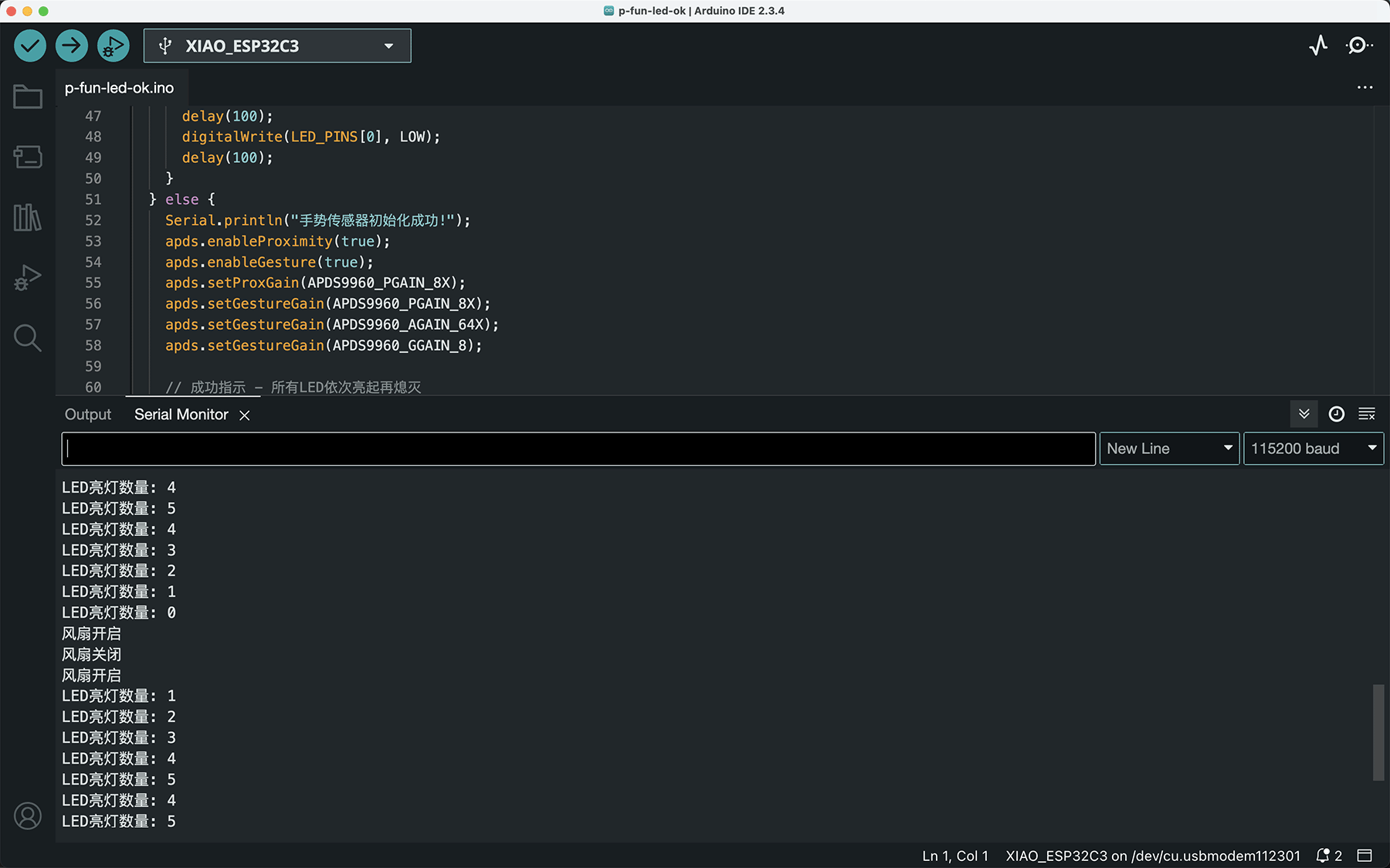
}The program provides feedback in the serial monitor when running, as shown below.

Feedback in the serial monitor when the program is running
4.3 Program Function Description
- Pin Redefinition and Initialization:
- Using RX/D7(GPIO20) and TX/D6(GPIO21) as SDA and SCL pins for software I2C
- Using MOSI/D10(GPIO10) as fan control pin
- Defining and initializing 6 onboard LEDs (D0-D5)
- All devices initially in off state
- Gesture Recognition and Processing:
- Right swipe gesture: Turn on fan
- Left swipe gesture: Turn off fan
- Upward swipe gesture: Increase number of lit LEDs
- Downward swipe gesture: Decrease number of lit LEDs
- LED Control Function:
updateLEDs()function controls sequential lighting/extinguishing of LEDs- Number of lit LEDs (6-0) serves as visual feedback of system status
- Debounce Processing:
- Added 500ms gesture recognition interval to prevent accidental triggers or repeated recognition
5. Hardware Implementation
5.1 Physical Connection
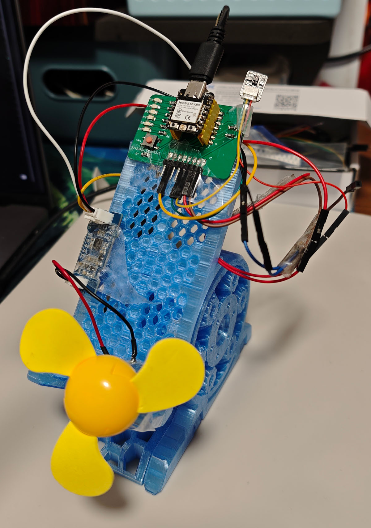
Following the design plan, I used Dupont cables to connect the gesture sensor and fan module to the XIAO extension board, and secured them on a phone stand with tape for easy operation and demonstration, as shown below.

Actual hardware connection, with gesture sensor connected to RX/TX pins and fan connected to MOSI pin
The main challenges encountered during connection were avoiding short circuits between pins and ensuring stable connections. Using different colored Dupont wires helped distinguish various connections and improve operational reliability.
5.2 Component Layout
To achieve optimal gesture recognition effect and fan airflow, the component layout considered the following:
- Gesture Sensor Placement:
- Using a phone stand to support the extension board and gesture sensor, keeping the sensor facing upward
- Sensor surface facing up for easy gesture operation from above
- Maintaining approximately 15cm of unobstructed space in front of the sensor
- Fan Position:
- Fan placed about 10cm below the sensor
- Ensuring fan airflow doesn't interfere with gesture recognition
- Secured firmly to prevent movement during operation
- Connection Wire Management:
- Using tape to secure connection wires, preventing loosening
- Keeping wires as short and direct as possible to reduce software I2C interference issues
The final component layout optimized gesture operation space and device placement
6. System Testing and Demonstration
6.1 Gesture Response Testing
I tested the recognition and system response of four gestures:
| Gesture Direction | Control Function | Recognition Success Rate | Notes |
|---|---|---|---|
| Right swipe | Turn on fan | ~92% | Stable recognition |
| Left swipe | Turn off fan | ~90% | Relatively stable recognition |
| Upward swipe | Increase LED count | ~85% | Occasionally misidentified as downward swipe |
| Downward swipe | Decrease LED count | ~85% | Occasionally misidentified as upward swipe |
Test results show that left/right gesture recognition rates are slightly higher than up/down gestures, which relates to the gesture sensor layout and light reflection characteristics. The added 500ms gesture recognition interval effectively prevented accidental triggers.
6.2 LED Sequence Lighting Effect
The LED sequence lighting demonstrated good visual feedback effects:
- Precise control of 0-6 LEDs lighting through up/down gestures
- LEDs light up/turn off in sequence, providing intuitive status indication
- LED initialization animation during system startup provided visual confirmation
6.3 Fan Control Response
Fan control exhibited the following characteristics:
- Right swipe gesture reliably turns on the fan
- Left swipe gesture reliably turns off the fan
- Fan response is quick, with virtually no delay
- Directly using high/low level control, simple and reliable operation
6.4 System Demonstration Video
The video demonstrates the complete system functionality, including:
- Using right swipe gesture to turn on the fan
- Using left swipe gesture to turn off the fan
- Using upward swipe gesture to increase the number of lit LEDs
- Using downward swipe gesture to decrease the number of lit LEDs
7. Problems and Solutions
7.1 Problems Encountered
- Pin Reuse Challenge:
- Problem: Custom extension board didn't expose dedicated I2C pins
- Solution: Using ESP32C3's software I2C functionality, repurposing RX/TX as SDA/SCL
- Consequence: Unable to use serial communication simultaneously when using these pins, but can be used after program upload is complete
- PWM and Analog Output Compatibility:
- Problem: ESP32C3's
ledcSetup/ledcWritefunctions reported errors during compilation - Solution: Switched to standard
digitalWritefunction for digital control - Impact: Could only implement on/off control, unable to adjust speed, but met our simplified control requirements
- Problem: ESP32C3's
- Unstable Gesture Recognition:
- Problem: In initial testing, up/down gestures were frequently misidentified
- Cause: Ambient light interference and inconsistent gesture angles
- Solution: Added simple light shield and gesture recognition delay (500ms)
- Power Voltage Challenge:
- Problem: Gesture sensor recommends 5V, but extension board only provides 3.3V
- Solution: Connected the sensor directly to 3.3V, though this might reduce detection distance
- Test Result: Still works normally at 3.3V, detection distance about 70% of nominal value
7.2 Improvement Directions
- Hardware Design Optimization:
- Expose dedicated I2C pins in the next version of the extension board
- Add 5V output option to improve sensor compatibility
- Consider adding motor driver circuit to support precise PWM control
- Gesture Recognition Enhancement:
- Optimize gesture recognition algorithm to reduce misidentification
- Add more gesture combinations to achieve richer functions
- Add proximity detection for automatic on/off
- User Interface Optimization:
- Design richer LED display modes, such as flashing, flowing light effects
- Add sound feedback to improve interaction experience
- Develop two-handed collaborative gestures to increase control dimensions
8. Conclusion and Reflection
8.1 Project Achievements
This project successfully overcame extension board design limitations, implemented a gesture-controlled fan and LED system, and accomplished the following goals:
- Solved the connection problem through software I2C, achieving communication between the APDS-9960 gesture sensor and XIAO
- Successfully controlled the Grove mini fan, implementing simple on/off control
- Implemented sequential lighting control of onboard LEDs, providing visual feedback
- Designed an intuitive gesture interaction system, making control more natural
The project demonstrated ESP32C3's powerful I/O reuse capability and showed how to implement innovative functions under existing hardware limitations.
8.2 Learning Outcomes
- Software I2C Implementation and Application:
- Learned ESP32C3's pin mapping technology
- Understood how communication timing and electrical characteristics affect signal quality
- Mastered methods for handling non-standard hardware configurations
- Multi-Device Control Skills:
- Learned basic methods for controlling actuators like fans
- Mastered LED sequence control techniques
- Understood the importance of visual feedback in human-computer interaction
- System Integration Capability:
- Successfully integrated input device (gesture sensor) and multiple output devices (fan and LEDs)
- Built a complete interaction system
- Solved inter-device communication and collaborative working issues
- Problem Solving and Innovative Thinking:
- Found software solutions under hardware limitations
- Discovered and solved practical operation problems through experimentation
- Learned to use existing resources to achieve innovative functions
8.3 Connection to Final Project
This project is an important technical validation for my final project "Smart Fantasy Lantern", especially:
- Verified the reliability and applicability of the APDS-9960 gesture sensor at 3.3V
- Tested ESP32C3's software I2C functionality and GPIO control capability
- Explored gesture interaction system design methods, laying an interaction foundation for the final project
- Verified the feasibility of using ESP32C3 to control motors, providing reference for the lampshade rotation mechanism
These technologies and experiences will be directly used in LED strip control and interaction design in the final project, and are key foundations for project success. Through this experiment, I am more confident that under existing hardware conditions, I can achieve the ideal "Smart Fantasy Lantern" interactive control scheme.
 Lei Feng Fab Academy 2025