Week 9 Individual Assignment: Adding an
Distance Sensor to XIAO Expansion Board
Project Introduction
The main goal of this week's individual project is to add a sensor to my microcontroller board and read data from it. To achieve this goal, I chose the Grove - Ultrasonic Ranger distance sensor, a non-contact distance measurement module operating at 40KHz.
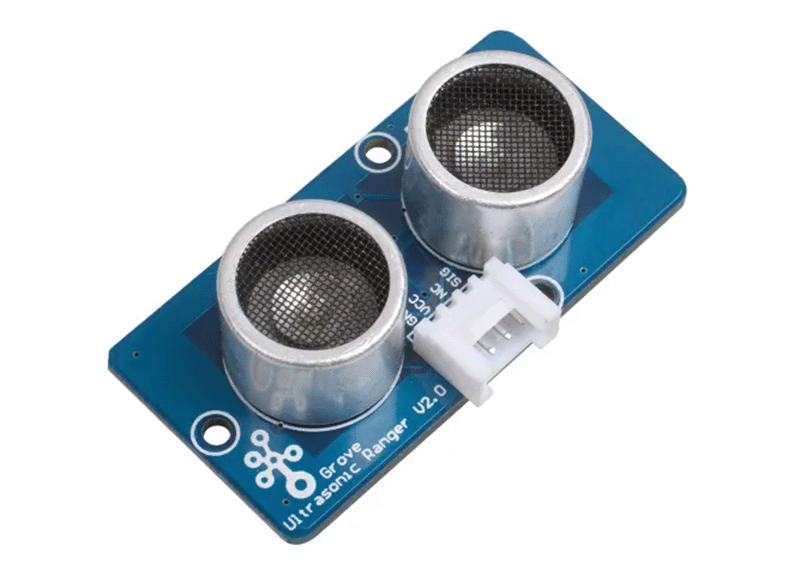
Grove - Ultrasonic Ranger distance sensor
For this week's assignment, I've outlined several specific objectives including:
- Understanding the working principles of ultrasonic distance sensors
- Designing the sensor circuit and connecting it to the XIAO ESP32C3
- Writing programs to test the distance measurement functionality
- Visualizing the measurement results
- Documenting the entire design, manufacturing, and testing process
Understanding the Working Principles of Ultrasonic Distance Sensors
Introduction to Grove - Ultrasonic Ranger
The Grove - Ultrasonic Ranger is an ultrasonic distance module produced by Seeed Studio, featuring a standard Grove interface for easy integration with various microcontrollers (such as XIAO development boards). The image below shows the purchased sensor on the left and my completed development board on the right.
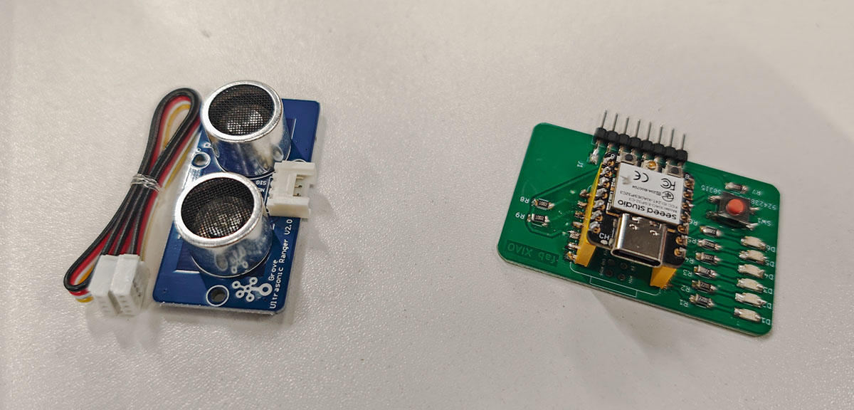
Comparison between the Grove - Ultrasonic Ranger module (left) and my XIAO development board
Ultrasonic Distance Measurement Principles
Ultrasonic distance measurement is a technology based on sound wave propagation time to measure distance. The working principle is as follows:
- Emitting Ultrasonic Waves: The sensor emits 8 pulses of 40KHz ultrasonic waves
- Waiting for Echo: The ultrasonic waves propagate through the air and reflect back upon hitting an obstacle
- Receiving Echo: The sensor receives the reflected ultrasonic waves
- Calculating Distance: The distance is calculated based on the time difference between emission and reception of the ultrasonic waves
Distance calculation formula: Distance = Echo Signal High Level Time × Speed of Sound (340m/s) ÷ 2
The division by 2 accounts for the round-trip distance traveled by the ultrasonic waves.
Grove - Ultrasonic Ranger Technical Specifications
According to the official Wiki documentation, the Grove - Ultrasonic Ranger has the following technical characteristics:
| Parameter | Specification |
|---|---|
| Operating Voltage | 3.2V-5.2V |
| Operating Current | 8mA |
| Ultrasonic Frequency | 40KHz |
| Measuring Range | 2-350cm |
| Resolution | 1cm |
| Output Method | PWM |
| Dimensions | 50mm × 25mm × 16mm |
| Weight | 13g |
| Measuring Angle | 15 degrees |
| Operating Temperature | -10~60℃ |
| Trigger Signal | 10μS TTL |
| Echo Signal | TTL |
The core sensor Ceramic Ultrasonic Sensor NU40C16T/R-1 documentation provides a test circuit as shown below.
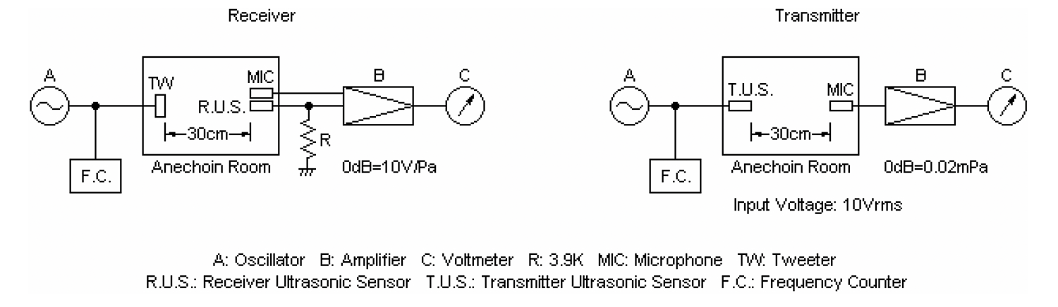
Test circuit provided in the Ceramic Ultrasonic Sensor NU40C16T/R-1 documentation
This test circuit diagram shows the test configuration for the ultrasonic sensor (NU40C16T/R-1), divided into Receiver and Transmitter sections. I will explain each element and the overall working principle:
Receiver Circuit
The left side shows the receiver test setup:
- A: Oscillator - Provides the test signal
- TW: Tweeter - Used to emit sound waves
- F.C.: Frequency Counter - Monitors signal frequency
- MIC - Standard reference microphone, receives sound waves simultaneously with the receiver ultrasonic sensor (R.U.S.)
- R.U.S.: Receiver Ultrasonic Sensor - The receiver being tested
- R: 3.9K Resistor - Provides load for the signal
- B: Amplifier - Amplifies the sensor output signal
- C: Voltmeter - Measures output voltage, reference value 0dB=10V/Pa
Transmitter Circuit
The right side shows the transmitter test setup:
- A: Oscillator - Provides 10Vrms input voltage
- F.C.: Frequency Counter - Monitors signal frequency
- T.U.S.: Transmitter Ultrasonic Sensor - The transmitter being tested
- MIC - Used to receive ultrasonic waves produced by the transmitter
- B: Amplifier - Amplifies signals received by the microphone
- C: Voltmeter - Measures the amplified signal, reference value 0dB=0.02mPa
Testing Principles and Procedures
- Receiver Testing:
- The oscillator generates a 40kHz test signal
- The tweeter (TW) converts the electrical signal into ultrasonic waves
- In an anechoic room at 30cm distance, both the reference microphone and the receiver under test receive the ultrasonic waves
- The receiver's output signal goes through a 3.9K resistor to ground, then is amplified
- The voltmeter measures the amplified signal, comparing it with the standard 0dB=10V/Pa to determine the receiver's sensitivity
- Transmitter Testing:
- The oscillator outputs a 10Vrms 40kHz signal to the transmitter under test
- The transmitter produces ultrasonic waves
- At 30cm distance in an anechoic room, the standard microphone receives the ultrasonic waves
- The microphone signal is amplified
- The voltmeter measures the amplified signal, comparing it with the standard 0dB=0.02mPa to determine the transmitter's sound pressure level
Test Environment
The anechoic room is a key environment for testing, which:
- Eliminates environmental reflections and interference
- Provides stable, consistent test conditions
- Ensures the accuracy and repeatability of measurement results
This testing method allows precise measurement of key performance parameters of the sensors, including center frequency (40kHz±1kHz), transmitter sound pressure level (≥114dB), and receiver sensitivity (≥-68dB).
Workflow
The Grove - Ultrasonic Ranger workflow is as follows:
- Initialization: The microcontroller initializes the sensor
- Triggering Measurement: The microcontroller sends a high-level trigger signal of at least 10μs to the sensor
- Emitting Ultrasonic Waves: Upon receiving the trigger signal, the sensor emits 8 pulses of 40KHz ultrasonic waves
- Waiting for Echo: The sensor waits for the ultrasonic waves to reflect back
- Receiving Echo: The sensor receives the reflected ultrasonic waves and outputs a high-level signal proportional to the distance
- Calculating Distance: The microcontroller measures the duration of the high-level signal and calculates the distance using the formula
Interface with Microcontrollers
The Grove - Ultrasonic Ranger uses a standard Grove interface to communicate with microcontrollers:
- VCC: Connected to the microcontroller's 3.3V or 5V power supply
- GND: Connected to the microcontroller's ground
- SIG: Connected to a digital pin on the microcontroller, used for sending trigger signals and receiving echo signals
- NC: Not connected
A feature of the Grove - Ultrasonic Ranger is that the trigger signal and echo signal share a single SIG pin, which simplifies wiring but requires special handling in software.
Designing the Sensor Circuit and Connecting it to the XIAO ESP32C3 Development Board
Hardware Connection Plan
The 8-pin connector on my XIAO development board is shown in the figure below.
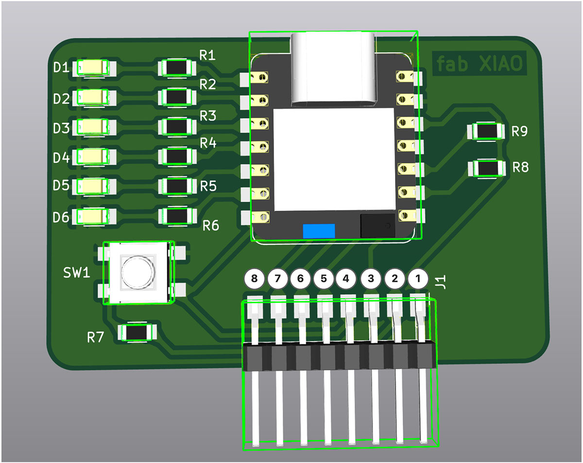
Pin numbering on my designed XIAO development board
Function description of the 8-pin connector (J1) on the XIAO ESP32C3 expansion board:
- GND - Ground connection
- 3.3V - 3.3V power output
- RX/D7 - Serial receive pin (GPIO20)
- TX/D6 - Serial transmit pin (GPIO21)
- SCK/D8 - SPI clock signal (GPIO8), marked with * as a Strapping pin
- MISO/D9 - SPI master input slave output (GPIO9), marked with * as a Strapping pin
- MOSI/D10 - SPI master output slave input (GPIO10)
- RST/Other available pins - Can be used as reset signal or for other expansion functions
Connecting the Grove - Ultrasonic Ranger distance sensor to the XIAO ESP32C3 development board is very simple and direct. The sensor only requires three pin connections, including power, ground, and signal line.
Connection Details
| Grove - Ultrasonic Ranger Pin | XIAO ESP32C3 Pin | Development Board 8-pin Connector (J1) Number | Function |
|---|---|---|---|
| VCC (Red Wire) | 3.3V | 2 | Power positive |
| GND (Black Wire) | GND | 1 | Power ground |
| SIG (Yellow Wire) | D6 / GPIO21 | 4 | Signal line (shared for trigger and echo) |
| NC (White Wire) | Not connected | Unused |
Wiring Diagram
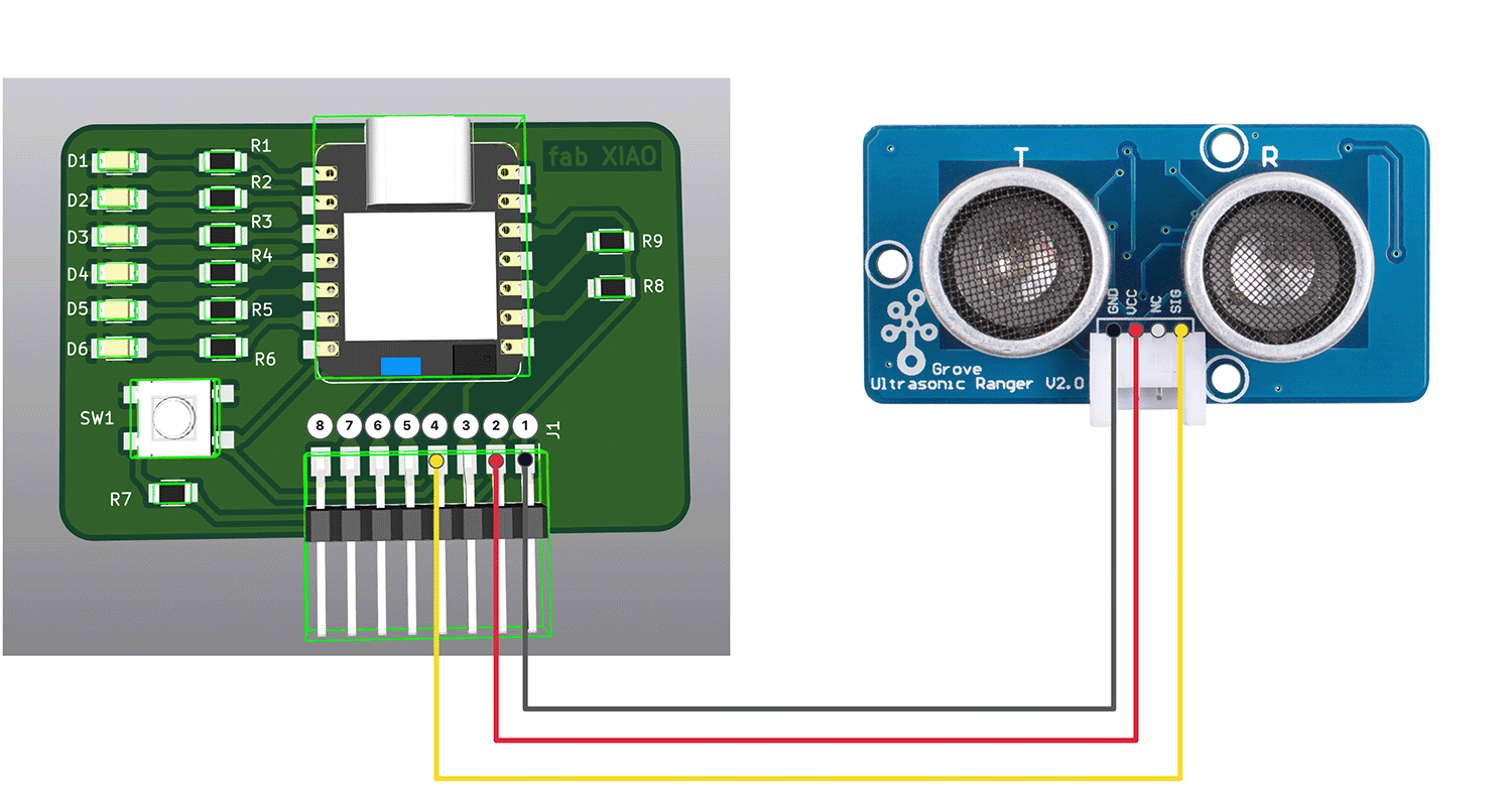
Wiring diagram of XIAO ESP32C3 and Grove - Ultrasonic Ranger module
Hardware Connection Notes
- Power Selection: The Grove - Ultrasonic Ranger can operate within a voltage range of 3.2V-5.2V, and the XIAO ESP32C3's 3.3V output meets this requirement.
- Signal Line Connection: The sensor's SIG pin is connected to the XIAO ESP32C3's digital pin D6, used for sending trigger signals and receiving echo signals.
- Sensor Placement: The placement of the ultrasonic sensor is very important, ensure that:
- There are no obstructions in front of the sensor
- The measurement area is no less than 0.5 square meters and has a smooth surface
- The sensor is firmly secured to avoid movement that could cause measurement errors
- Connection Wire Length: Use the shortest possible connection wires to reduce signal interference. Recommended wire length should not exceed 20cm.
Actual Connection Implementation
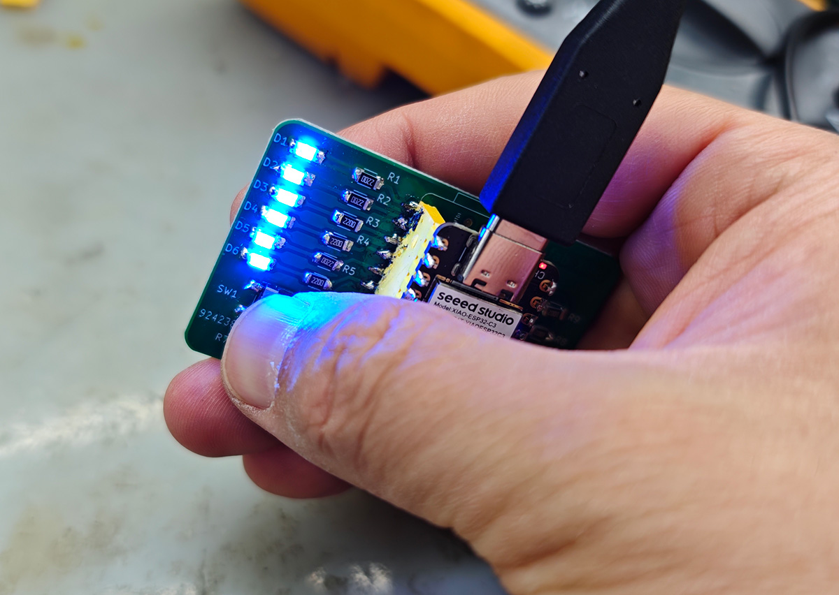
Since the project is in the prototype stage, I used jumper wires for temporary connections, connecting the Grove - Ultrasonic Ranger module to the previously designed XIAO ESP32C3 expansion board. The completed connection is shown in the figure below:
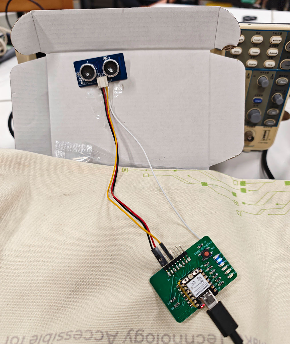
Connection of the homemade XIAO ESP32C3 development board with the Grove - Ultrasonic Ranger module
Programming and Testing the Distance Measurement Function
Development Environment Setup
The development environment is based on Arduino IDE, including the following steps:
- Installing XIAO ESP32C3 Board Support:
- Add Seeed Studio XIAO board support in Arduino IDE.
- Select "
XIAO_ESP32C3" as the target board.
- Installing Ultrasonic Ranger Library:
- Search for
grove Ultrasonicin the Arduino IDE library manager. - Install
Grove Ultrasonic Ranger by Seeed Studio, as shown below.
- Search for
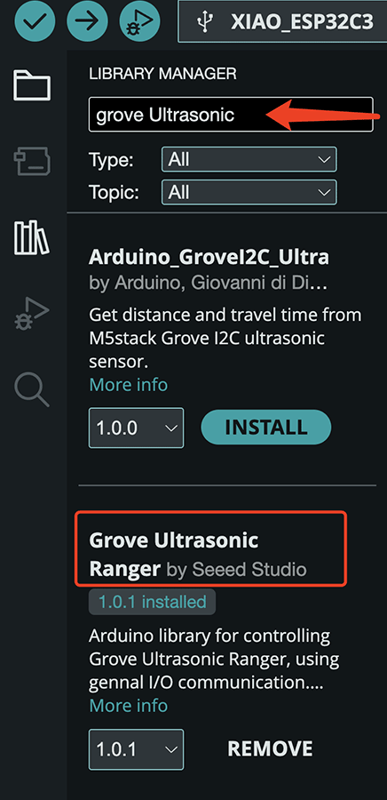
Need to search and install Grove Ultrasonic Ranger by Seeed Studio library in the Library Manager
- Test Environment Preparation:
- Set serial monitor baud rate to 115200.
- Prepare the test environment, ensuring stable measurement conditions.
Test Program Code
Based on the test program provided in the Wiki documentation:
#include "Ultrasonic.h"

Ultrasonic ultrasonic(7);
void setup()
{
 Serial.begin(9600);
}
void loop()
{
 long RangeInInches;
 long RangeInCentimeters;

 Serial.println("The distance to obstacles in front is: ");
 RangeInInches = ultrasonic.MeasureInInches();
 Serial.print(RangeInInches);//0~157 inches
 Serial.println(" inch");
 delay(250);

 RangeInCentimeters = ultrasonic.MeasureInCentimeters(); // two measurements should keep an interval
 Serial.print(RangeInCentimeters);//0~400cm
 Serial.println(" cm");
 delay(250);
}I made a few modifications, changing Ultrasonic ultrasonic(7); to Ultrasonic ultrasonic(21); (to match the XIAO ESP32C3's pin D6/GPIO21 numbering, note that you need to use the GPIO number here, otherwise no signal will be received), and also simplified the output to only display the values to facilitate graphical display in the serial plotter. The modified program is shown below:
#include "Ultrasonic.h"

// Use the correct GPIO number
Ultrasonic ultrasonic(21);  // Corresponds to XIAO ESP32C3's D6/GPIO21

void setup() {
  Serial.begin(115200);  // XIAO ESP32C3 typically uses 115200 baud rate
  delay(1000);  // Wait for serial connection

  // Send a unit information at the start
  // Most plotters will ignore this line, but it's useful information for human users
  Serial.println("Distance(cm)");
}

void loop() {
  // Measure distance
  long distance = ultrasonic.MeasureInCentimeters();

  // Output only the value, without text, suitable for serial plotter
  Serial.println(distance);

  delay(500);  // Measure once every 500 milliseconds
}After running the program, the measured distance when I extend my hand can be seen via the serial monitor, as shown below.
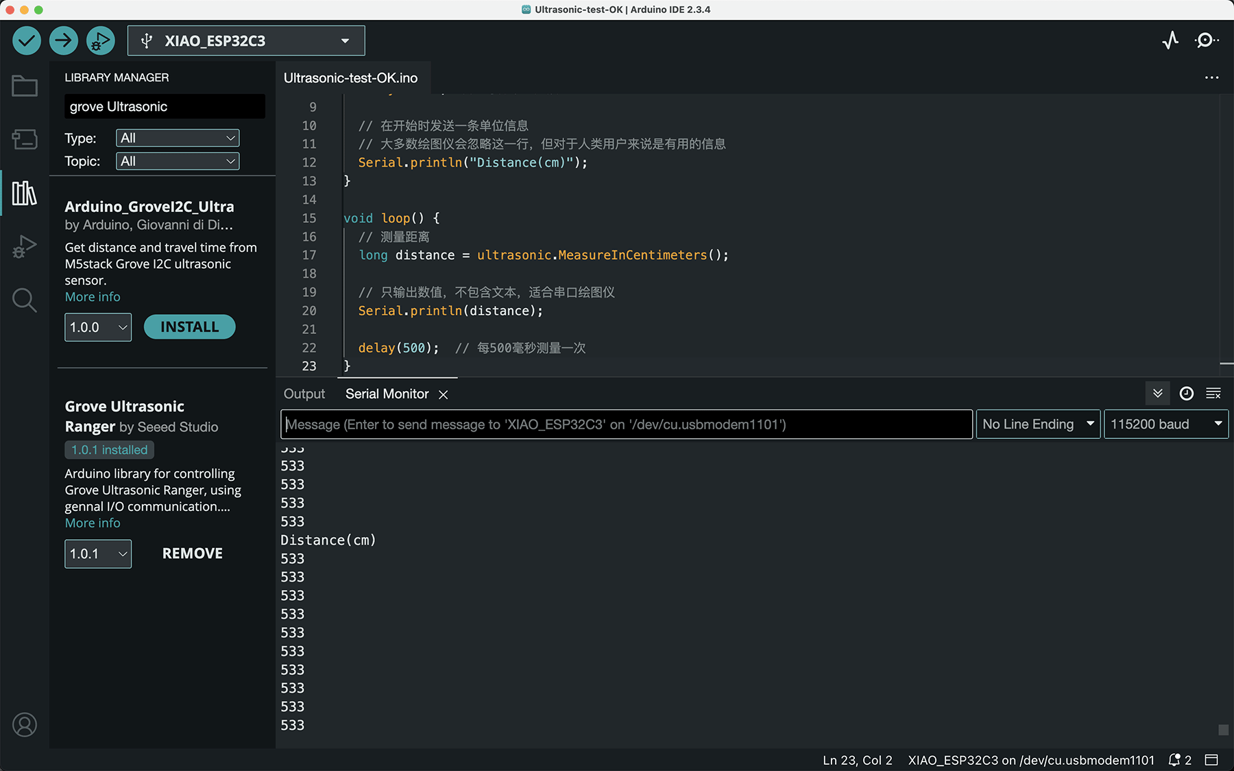
Serial monitor begins to output the measured distance
Data Visualization
Clicking on the serial plotter in the upper right corner of Arduino IDE opens a graphical window, displaying the measured distance changes in a visual format, as shown below.
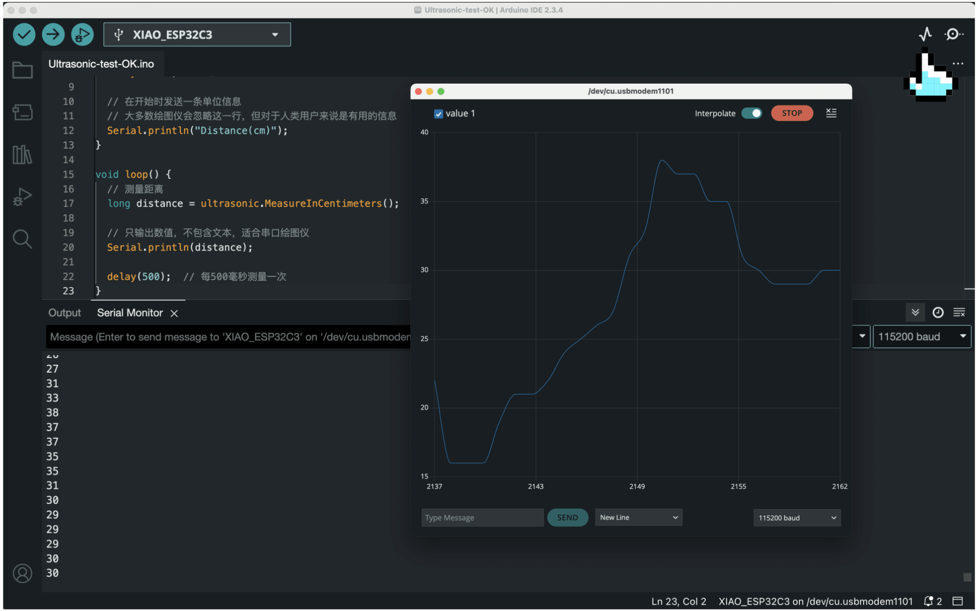
Serial plotter dynamically displays the measured distance changes in a visual way
Testing Methods and Results
I set up a simple distance testing environment with a ruler, and at relatively close distances, it was quite accurate.
Distance testing video, the serial monitor on the screen reports the measurement distance (cm) output by the sensor
I designed a systematic testing process to comprehensively evaluate the distance measurement functionality:
- Basic Function Testing:
- Placing test objects at different distances
- Recording the measurement results and actual distances
- Calculating measurement errors
- Testing Different Materials:
- Testing the reflection effects of objects with different materials
- Hard flat surfaces (such as wooden boards): high measurement accuracy, error about ±1cm
- Soft materials (such as fabric): weaker reflection, larger measured distances
- Irregular surfaces: greater fluctuation in measurement results
- Testing Different Angles:
- Testing measurement effects when objects are at different angles relative to the sensor
- Vertical placement: most accurate measurement
- Inclined placement (within 15°): increased measurement error but still acceptable
- Inclined placement (>15°): significantly increased measurement error
- Long-term Stability Testing:
- Running continuously for 30 minutes, recording the stability of measurement results
- Analyzing the drift of measurement data
The test results show that this ultrasonic distance measurement system has good stability and reliability in normal usage environments, with measurement errors within ±2cm, fully meeting general application requirements.
Adding Distance Value Feedback with Development Board LEDs
Now that we can get distance output from the sensor, we can create interesting applications. I thought of utilizing the 6 LEDs on the development board to provide distance feedback. If the distance is within 10cm, D1 will light up; then for every additional 10cm increase in distance, the next LED in sequence will light up until D6.
Planning to use the 6 LEDs on my DIY development board to provide distance feedback indication
Below is the ultrasonic distance measurement test program I developed, which can measure the distance between objects and the sensor, and provide feedback through LEDs and serial output.
/**
 * XIAO ESP32C3 Ultrasonic Distance Measurement Program + LED Distance Display
 * Using Grove Ultrasonic Ranger sensor
 *
 * Author: Lei Feng
 * Date: 2025-03-25
 */

#include "Ultrasonic.h"

// Sensor pin definition
#define ULTRASONIC_PIN 21  // Corresponds to D7/GPIO21

// LED pin definitions - using 6 LEDs on the expansion board
const int LED_PINS[] = {D0, D1, D2, D3, D4, D5};
const int LED_COUNT = 6;

// Create ultrasonic sensor object
Ultrasonic ultrasonic(ULTRASONIC_PIN);

// Define variables
long distance = 0;
unsigned long lastMeasureTime = 0;
const unsigned long MEASURE_INTERVAL = 500; // Measurement interval (milliseconds)

// Distance display configuration
const int DISTANCE_PER_LED = 10; // Each LED represents 10cm
const int MAX_DISPLAY_DISTANCE = LED_COUNT * DISTANCE_PER_LED; // Maximum display distance 60cm

/**
 * Initialization function
 */
void setup() {
  // Initialize serial communication
  Serial.begin(115200);

  // Wait for serial connection
  delay(1000);
  Serial.println("\n\nXIAO ESP32C3 - Ultrasonic Distance Measurement System Initialization");

  // Initialize LED pins as outputs
  for (int i = 0; i < LED_COUNT; i++) {
    pinMode(LED_PINS[i], OUTPUT);
  }

  // LED test - sequentially light up all LEDs
  for (int i = 0; i < LED_COUNT; i++) {
    digitalWrite(LED_PINS[i], HIGH);
    delay(100);
  }

  // Turn off all LEDs
  for (int i = 0; i < LED_COUNT; i++) {
    digitalWrite(LED_PINS[i], LOW);
  }

  Serial.println("System ready! Starting distance measurement...");
  Serial.println("Distance display: Each LED represents 10cm distance");

  // Print CSV header for data recording
  Serial.println("Time(ms),Distance(cm),LED Count");
}

/**
 * Main loop function
 */
void loop() {
  // Timed distance measurement
  unsigned long currentTime = millis();
  if (currentTime - lastMeasureTime >= MEASURE_INTERVAL) {
    lastMeasureTime = currentTime;

    // Measure distance
    distance = ultrasonic.MeasureInCentimeters();

    // Check if sensor is working properly
    if (distance == 0) {
      Serial.println("Warning: Received distance of 0, please check sensor connection!");

      // LED flashing indication when sensor error
      blinkAllLEDs(3, 200);
    } else {
      // Output CSV format data
      Serial.print(currentTime);
      Serial.print(",");
      Serial.print(distance);
      Serial.print(",");

      // Calculate number of LEDs to light up
      int ledsToLight = 0;
      if (distance <= MAX_DISPLAY_DISTANCE) {
        ledsToLight = (distance + DISTANCE_PER_LED - 1) / DISTANCE_PER_LED;
      } else {
        ledsToLight = LED_COUNT; // Beyond maximum display distance, light up all LEDs
      }

      Serial.println(ledsToLight);

      // Light up corresponding number of LEDs based on distance
      updateLEDDisplay(ledsToLight);

      // Display detailed measurement information
      Serial.print("Distance: ");
      Serial.print(distance);
      Serial.print(" cm | LED: ");
      Serial.print(ledsToLight);
      Serial.println(" units");
    }
  }

  // Brief delay to avoid high CPU usage
  delay(50);
}

/**
 * Update LED display
 *
 * @param count Number of LEDs to light up
 */
void updateLEDDisplay(int count) {
  // Ensure count is within valid range
  if (count > LED_COUNT) {
    count = LED_COUNT;
  }

  // Update LED states
  for (int i = 0; i < LED_COUNT; i++) {
    if (i < count) {
      digitalWrite(LED_PINS[i], HIGH); // Light up
    } else {
      digitalWrite(LED_PINS[i], LOW);  // Turn off
    }
  }
}

/**
 * All LEDs flash simultaneously
 *
 * @param times Number of flashes
 * @param delayTime Flash interval time (milliseconds)
 */
void blinkAllLEDs(int times, int delayTime) {
  for (int i = 0; i < times; i++) {
    // Light up all LEDs
    for (int j = 0; j < LED_COUNT; j++) {
      digitalWrite(LED_PINS[j], HIGH);
    }
    delay(delayTime);

    // Turn off all LEDs
    for (int j = 0; j < LED_COUNT; j++) {
      digitalWrite(LED_PINS[j], LOW);
    }
    delay(delayTime);
  }
}After running the program, the serial monitor will display the measured distance and the number of LED lights lit, as shown below.
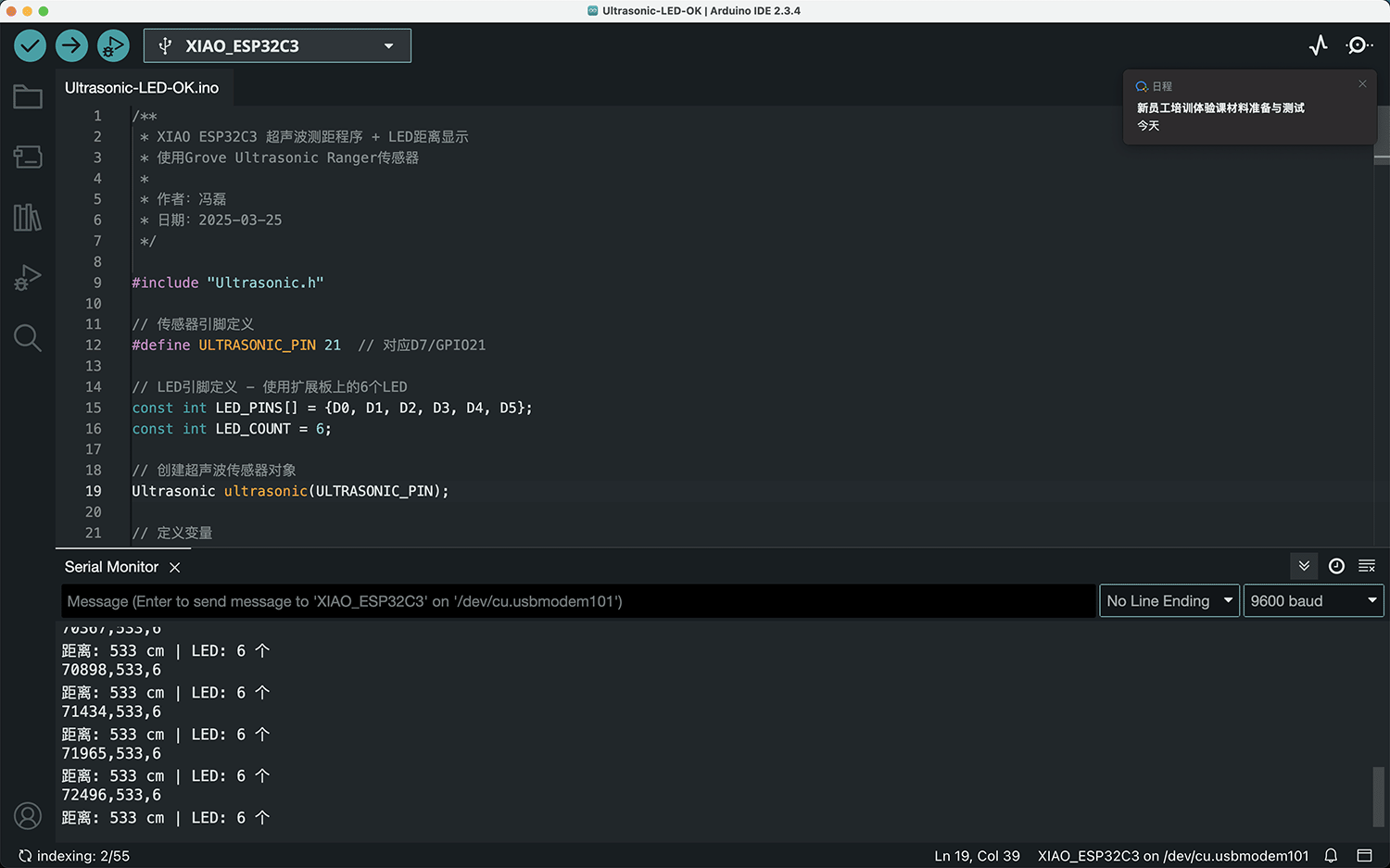
Serial monitor displays the measured distance and number of LED lights
The video below demonstrates the interactive effect of the device changing the number of LEDs based on the measured distance.
Main Issues Encountered During Measurement
During the measurement process, I encountered the following main challenges:
- Measurement Instability Issues:
- In some cases, measurement results would show jumps or abnormal values.
- This was especially true when measuring irregular surfaces or inclined objects, where measurement results were unstable.
- Blind Zone Issue:
- The sensor cannot accurately measure distances within 2cm (blind zone).
- Need to avoid placing objects within the blind zone.
- Angle Limitations:
- The sensor's measurement angle is limited (about 15 degrees), objects beyond this range may not be accurately detected.
- Need to ensure the measured object is within the sensor's detection range.